MotoCrane ULTRA User manual

ULTRA Troubleshooting Guide v2.0
July 2020
This guide helps users diagnose and repair issues in the field.
It should be used in conjunction with the ULTRA Operation Manual.
If a quick fix is available, one is prescribed. If a quick fix is not possible, we give a service
procedure for repair using the spare parts in the Deadlock Service Kit (available for purchase
online). Without a Deadlock Service Kit, spare parts can be purchased individually or the
affected modules can be returned to MotoCrane for repair.
Via MotoCrane Academy, Certified Technicians and Operators are trained on how to perform
these more common service procedures. Find more information at
www.motocrane.com/academy.
1

Contents
Understanding System Feedback 3
COM and Power LEDs 3
GUI Warning and Error Messages 4
Diagnosing Common Issues 5
“I have anodizing/finish problems” 5
“Grease is Leaking from the Base” 5
“Swing is not working” 6
“Lift is not working” 7
“The system is not turning on” 8
Appendix 1: Diagnosis Procedures 9
External Deactivation of Lift Drive Brake 9
“Remove PSU Top” 10
“Remove 24V Power Fuse” 10
“Check Power Fuse for Continuity” 10
“Unplug CAN-TRVL, Check Pins 3 and 4 for Continuity” 11
“Check continuity across Pins H and J on the BDU Main Power Input Socket” 11
“Open Base Pedestal Plate, Remove CAN IN Connector” 11
“Remove Lift Encoder Cover, Unplug CAN IN from Lift Encoder Board” 12
“Check continuity between pins H and J on the LDU Main Power Input Socket” 12
“Emergency Bypass Procedure” (for PSU Circuit Board failure) 12
Appendix 2: Error Codes Lookup Table 15
Revision History 29
2

Understanding System Feedback
ULTRA provides system feedback using two primary methods: LEDs and GUI Messages.
COM and Power LEDs
The Base Driver Unit, Base Pedestal, PSU, and Turret all contain LEDs to help quickly
identify problems with electrical connections.
The COM LED will turn on when the electronics at that location are successfully
communicating on the CAN-bus with the other parts of the system. If this LED turns off,
this indicates that either the electronics at that location have stopped functioning
properly, a wiring issue has developed that prevents normal communication to occur,
or in an extremely rare case that the COM LED has burned out.
The COM LEDs can help to diagnose cabling vs. electronics issues. If all COM LEDs are
off, this could be an issue with the Main Power Cable from the PSU to the Base. If only
the Base Driver Unit COM LED is on, this could indicate internal wiring problems in the
Base. If both the Base Driver Unit and Base Pedestal COM LEDs are on, but the Turret
COM LED is off, this could indicate a bad cable between the Base Pedestal and Turret,
or an LDU electronics failure.
Similarly, the Power LEDs indicate the presence of the 48V system power in their
respective locations. Power LEDs are also present in the PSU, to provide a visual
confirmation that the system power is connected and switched on.
** Please note: Due to inherent properties of the power management system, the
Power LEDs may remain dimly lit for a short while after the system power is turned off.
3

GUI Warning and Error Messages
ULTRA has multiple internal sensors and an error reporting system built into the GUI.
If an active error or warning is present, the respective red or yellow icon will be
displayed. A yellow icon indicates a warning, and the controller will beep once to alert
the user. A red icon indicates an error, and the controller will beep repeatedly until the
icon is touched or the DISARM physical switch is pressed by the user.
Touching the error or warning icon will bring you to the Status page, where you can
see a list of active errors and warnings. If you are experiencing an intermittent issue,
and the warning or error is not currently active, you can review events by navigating to
the System Log, which is accessible through the Diagnostics page. The System Log will
also provide a list of errors and warnings that have occurred, along with the time since
the event occurred (in 2 minute increments). Note that the System Log will only hold
the most recent 10 events, and is cleared upon power cycling the system.
From either the Status or System Log page, you can access the Code Lookup Table,
which will provide you with a short description of the error or warning and a
recommended first step for troubleshooting and clearing the issue. For reference, the
‘Controller - GUI’ section of the Operation Manual shows the location of the System
Log and Code Lookup buttons within their respective pages.
More detail is given below about each error message along with a description of what
to try if the first step does not work.
**When debugging any error or warning, first ensure that all cables are properly
connected and check the status of the COM and Power LEDs on all modules.
4

Diagnosing Common Issues
Please see the list of common symptoms below, and the procedure for fixing solving.
“I have anodizing/finish problems”
● Anodizing/finish problems in non-wear areas.
○ Cause: Some anodizing batches are more susceptible to fade/ color change
under UV exposure.
○ Operation Manual reference: N/A
○ Repair Procedure: Replace or re-finish problematic parts.
○ Warranty: Covered, manufacturing defect in fit/finish. The customer pays all
shipping costs, as outlined in Terms of Sale.
● Cracking Anodizing around boom fasteners.
○ Cause: Washers are needed to minimize surface abrasion.
○ Operation Manual: See ULTRA Boom + Isolator Setup on p. 21 to ensure
customers are using washers appropriately.
○ Repair Procedure: N/A
○ Warranty: Not covered. Normal wear and tear.
“Grease is Leaking from the Base”
● Some grease has become liquid and escaped through the grease ports.
○ Cause: As the swing axis moves, the grease is continually circulated within the
chamber and undergoes a transition from thick to thin, depending on its location
and temperature. Some thin grease may escape at times, but this is not a cause
for concern. Simply wipe it away and it should diminish over time.
○ Operation Manual: N/A
○ Repair Procedure: N/A
○ Warranty: N/A
5

YES
NO
NO YES
Is Swing Axis
MOTOR CMD moving
when the joystick is
moved?
Controller Giving Error Codes?
Go to DIAGNOSTICS
page on Controller
GUI
Go to STATUS page
on Controller GUI
(touch Error/Warning
notice)
NO YES
Is BDU MAIN
POWER STATUS
LED on? (green)
NO YES
Is Swing SPEED set
to 99 and SMOOTH
set to 0?
NO YES
Does Lift Joystick
function
normally?
SUCCESSFUL ADJUSTMENT
CANNOT
ADJUST
Adjust Swing
SPEED to 99 and
SMOOTH to 0
NO YES
Is E-STOP (DISARM)
released? (twisted
and pulled out)
Swing Joystick is
Faulty - replace it
Controller Circuit
Board is likely
damaged - needs
replacement
Release E-Stop
YES
NO
Is Base Pedestal
MAIN POWER
STATUS LED on?
(green)
NO YES
Is Turret MAIN
POWER STATUS
LED on? (green)
Electrical Problems
Exist Within the Base
- Contact MotoCrane
Customer Support
Base Driver Circuit
Board has failed -
BDU needs to be
replaced
Base Driver Circuit
Board has failed -
BDU needs to be
replaced
Main Power pathway may
be faulty - or PSU has
internal damage
Try replacement PSU and
cables if available
Otherwise, Contact
MotoCrane Customer
Support
Code 075 Code 130 Code 125
Base Driver Circuit
Board has failed -
BDU needs to be
replaced
Swing Joystick is
Faulty - replace it
Swing Joystick is
Faulty - replace it
3
2
1
1
1 2 2
4
5
"SWING IS NOT WORKING"
ISSUE 1)BDU failure
Solution: Replace BDU or contact MotoCrane Support
ISSUE 2)Swing joystick failure
Solution: Replace joystick or contact MotoCrane Support
ISSUE 3)Controller Board failure
Solution: Replace Controller board or contact MotoCrane Support
ISSUE 4)PSU/Cable failure
Solution: Replace PSU, Cables or contact MotoCrane Support
ISSUE 5)ULTRA Base failure
Solution: Contact MotoCrane Support
POSSIBLE ISSUES
After completing the flowchart, use the
key below to determine next steps.

YES
NO
NO YES
Is Lift Axis MOTOR
CMD moving when
the joystick is moved?
Controller Giving Error Codes?
Go to DIAGNOSTICS
page on Controller
GUI
Go to STATUS page
on Controller GUI
(touch Error/Warning
notice)
NO YES
Is LDU MAIN
POWER STATUS
LED on? (green)
NO YES
Is Lift SPEED set to
99 and SMOOTH set
to 0?
NO YES
Does Swing
Joystick function
normally?
SUCCESSFUL ADJUSTMENT
CANNOT
ADJUST
Adjust Lift SPEED
to 99 and SMOOTH
to 0
NO YES
Is E-STOP (DISARM)
released? (twisted
and pulled out)
Lift Joystick is
Faulty - replace it
Controller Circuit
Board is likely
damaged - needs
replacement
Release E-Stop
YESNO Is Base Pedestal
MAIN POWER
STATUS LED on?
(green)
NO YES
Is BDU MAIN
POWER STATUS
LED on? (green)
Electrical Problems
Exist Within the Unit -
Contact MotoCrane
Customer Support
Lift Driver Circuit
Board has failed -
LDU needs to be
replaced
Lift Driver Circuit
Board has failed -
LDU needs to be
replaced
Main Power pathway may
be faulty - or PSU has
internal damage
Try replacement PSU and
cables if available
Otherwise, Contact
MotoCrane Customer
Support
Code 035 Code 129 Code 125
Lift Driver Circuit
Board has failed -
LDU needs to be
replaced
Lift Joystick is Faulty
- replace it
Lift Joystick is Faulty
- replace it
3
2
1
1
122
4
5
"LIFT IS NOT WORKING"
YESNO Code 109 Also?
Check cables and
replace Base
Pedestal to Turret
cable if possible
Contact MotoCrane
Customer Support if
this is not an option
ISSUE 1)LDU failure
Solution: Replace LDU or contact MotoCrane Support
ISSUE 2)Lift joystick failure
Solution: Replace joystick or contact MotoCrane Support
ISSUE 3)Controller Board failure
Solution: Replace Controller board or contact MotoCrane Support
ISSUE 4)PSU/Cable failure
Solution: Replace PSU, Cables or contact MotoCrane Support
ISSUE 5)ULTRA Base or Turret failure
Solution: Contact MotoCrane Support
POSSIBLE ISSUES
After completing the flowchart, use the
key below to determine next steps.

NO YES
PSU Main Power Input Voltage
Meter On?
YES
NO Is power source >
42V?
YESNO PSU MAIN POWER
STATUS LED on?
(green)
"THE SYSTEM WON'T TURN ON"
Turn off PSU Main
Power Switch
Disconnect Controller
Cable from COM port
Provide Adequate
Power Source
Disconnect Main
Power Output Cable
from PSU
Turn on PSU Main
Power Switch
Turn off PSU Main
Power Switch
NO YESPSU MAIN POWER
STATUS LED on?
(green)
PSU is Damaged -
Replace PSU
*Assumes PSU Main Power ON/OFF Switch is already "ON"
and the Controller does not boot up and turn on
* Try different or new cables, if possible, before moving to
troubleshooting steps
Disconnect Main
Power Output Cable
from PSU
Turn on PSU Main
Power Switch
NO YES
Does Controller boot-
up and turn on?
There is likely a
problem with the 24V
line in the Base or
Turret
Turn off PSU Main
Power Switch Make sure the Base
Pedestal to Turret
Main Power Cable is
not connected
Use a multimeter to
check continuity
across pins H and J
on the BDU Main
Power Input Socket
NO YESIs there continuity
across pins H and J?
(short-circuit)
Use a multimeter to
check continuity
across pins H and J
on the LDU Main
Power Input Socket
Open Base Pedestal
Cover (using 2.5mm
hex key)
Turn off PSU Main
Power Switch
Unplug the 4-pin
"CAN-IN" connector
from the Swing
Encoder Circuit Board
NO YES
Is there continuity
across pins H and J?
(short-circuit)
Use a multimeter to
check continuity
across pins H and J
on the BDU Main
Power Input Socket
YES
NO Is there continuity
across pins H and J?
(short-circuit)
Replace BDU
Replace Swing
Encoder Circuit
Board
Contact MotoCrane
Customer Support -
this issue cannot be
isolated in the field
Try using a different
PSU to Base Main
Power Cable if
possible
Open Turret Fulcrum
Encoder Cover (using
3mm hex key)
Unplug the 4-pin
"CAN-IN" connector
from the Lift Encoder
Circuit Board
Use a multimeter to
check continuity
across pins H and J
on the LDU Main
Power Input Socket
NO YES
Is there continuity
across pins H and J?
(short-circuit)
Replace Lift
Encoder Circuit
Board
Replace LDU
Contact MotoCrane
Customer Support -
this issue cannot be
isolated in the field
Reconnect Main
Power Output Cable
to PSU
Disconnect Controller
COM Cable from
PSU
Turn on PSU Main
Power Switch
PSU MAIN POWER
STATUS LED is
probably burned out
NO YES
Do COM Lights
appear (blue) on the
Base and Turret?
Turn off PSU Main
Power Switch
Disconnect all cables
from PSU
Remove PSU top
cover
Remove 24V Power
Fuse
Use a multimeter to
check continuity of
fuse
YES NO
Is there continuity
across the fuse?
Replace PSU - 24V
DC/DC converter
has likely failed
* SOMETHING HAS BLOWN THE FUSE
FUSE OR PSU WILL NEED TO BE REPLACED
ONCE THE ROOT CAUSE IS ADDRESSED
Unplug the 4-pin
"CAN-TRVL"
connector from the
PSU Circuit Board
Use a multimeter to
check continuity
across pins 3 and 4
on the circuit board
YES
NO
Is there continuity
across the pins?
Try new Controller
cable if possible
Replace Controller if
this does not solve
the problem
Replace PSU -
Circuit board is
likely damaged
OR
Emergency Bypass
Procedure
(Appendix 1)
Plug Back in the
CAN-TRVL connector
ISSUE 1)PSU failure
Solution: Replace PSU or contact MotoCrane Support
** EMERGENGY BYPASS OPTION - see Appendix A
ISSUE 2)Controller failure
Solution: Replace Controller or contact MotoCrane Support
ISSUE 3)Lift Encoder Board failure
Solution: Replace Lift Encoder Board or contact MotoCrane
Support
ISSUE 4)LDU failure
Solution: Replace LDU or contact MotoCrane Support
ISSUE 5)Swing Encoder Board failure
Solution: Replace Swing Encoder Board or Contact
MotoCrane Support
ISSUE 6)BDU failure
Solution: Replace BDU or Contact MotoCrane Support
ISSUE 7)Multiple issues - requires further debugging
Solution: Contact MotoCrane Support
POSSIBLE ISSUES
After completing the flowchart, use the
key below to determine next steps.
1
1
7
1
2
34
56
7
SEE APPENDIX 1

Appendix 1: Diagnosis Procedures
External Deactivation of Lift Drive Brake
In a rare situation, it is possible that the lift motor driver electronics could fail due to
extreme overuse, disregard for system warnings, faulty cables, improper system power
supply, among others. Because the nature of the lift drive brake is ‘fail-safe’, this means
that when the system is unpowered (more specifically, the lift motor driver electronics
are not receiving power), the brake is activated and the lift axis will not move, except in
the case of extreme imbalance between payload and counterweight. In the event that
the lift motor driver electronics stop working, and the lift axis is stuck in an undesirable
position, the following steps can be taken to manually unlock the lift axis:
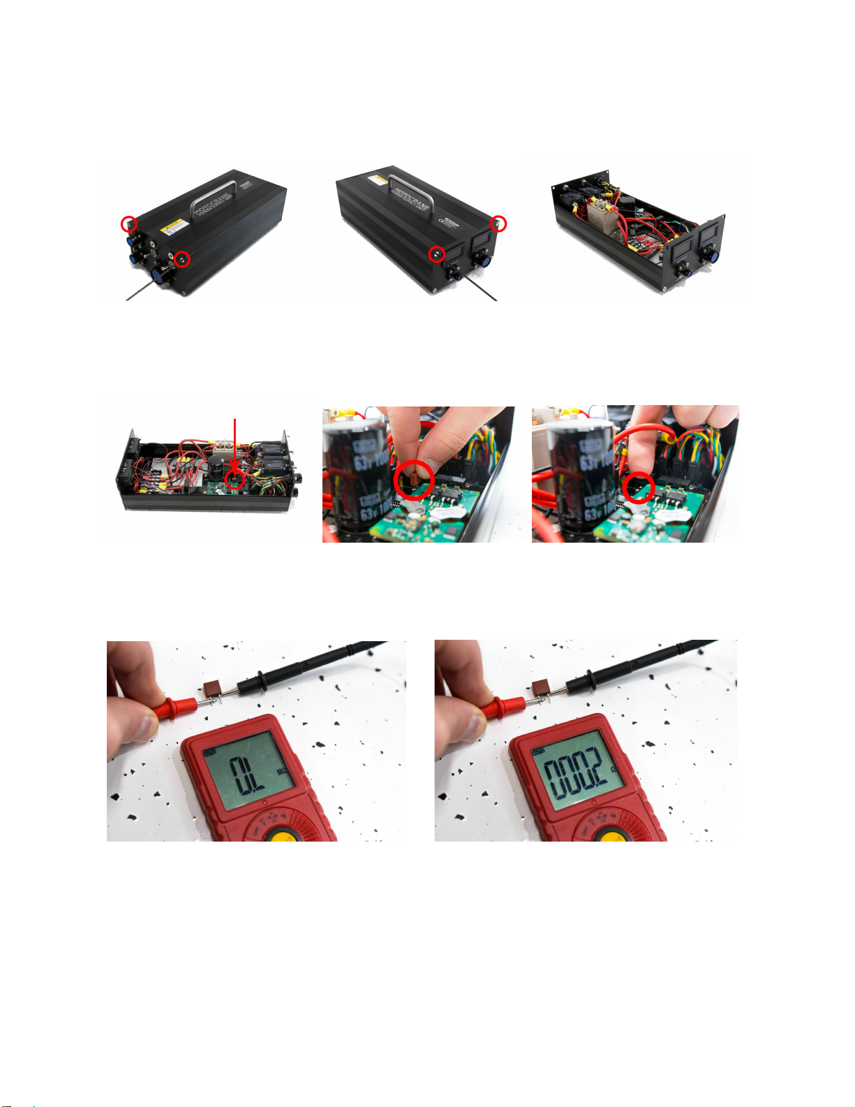
1. Turn off power from the system and remove the short cable connecting the Base
Pedestal to the Turret
2. Plug the main power input cable directly into the socket on the Turret (this cable
normally connects directly to the Base Driver Unit)
3. Ensure the other side of the main power input cable is connected to the PSU
4. Remove the small rectangular cover on the Turret, immediately adjacent to the
main power input socket (there are two small flat-head cap screws to remove)
5. Turn on the main power switch on the PSU
6. Depress and latch the button that was exposed by removing the rectangular
cover on the Turret
7. An audible click should be heard when this button is pressed, and the brake
should be deactivated
8. Manually position the boom to the desired location
9. Press the button again to un-latch it
10.Turn off the main power switch on the PSU
11.Replace the rectangular cover back on the Turret
Note that this feature is an immediate solution for re-positioning the fulcrum and
boom, in the event that the system cannot otherwise be transported or disassembled
normally. Service will still be required to repair the electronics and return the system to
normal operating conditions.
9

“Remove PSU Top”
“Remove 24V Power Fuse”
“Check Power Fuse for Continuity”
NO Continuity YES Continuity
10

“Unplug CAN-TRVL, Check Pins 3 and 4 for Continuity”
“Check continuity across Pins H and J on the BDU Main Power Input
Socket”
NO Continuity YES Continuity
“Open Base Pedestal Plate, Remove CAN IN Connector”
11

“Remove Lift Encoder Cover, Unplug CAN IN from Lift Encoder Board”
“Check continuity between pins H and J on the LDU Main Power Input
Socket”
NO Continuity YES Continuity
“Emergency Bypass Procedure” (for PSU Circuit Board failure)
NOTE: This procedure is only recommended for emergency and time-critical situations. For
everything else, the best course of action is to wait for a replacement PSU or PSU Circuit Board
in order to restore the system to its original state. Operating the PSU without the capacitors and
without a proper fuse may present risks to the rest of the system, and lacks protection for
potential (but unlikely) failures in other modules, such as the Base, Turret, or Controller.
Additional information about this procedure:
We have seen isolated failures of two capacitors in particular (C10 and C11 on the PSU Circuit
Board), which results in a short circuit of the low power 24V communication power line in the
system, blowing the fuse in the PSU and preventing the system from powering up. Although
these capacitors are on the board for a reason, they are not absolutely essential to the short
term operation of the circuit. Therefore, the emergency bypass procedure involves physically
removing these capacitors from the board in order to remove the short circuit condition and
allow for operation of the unit until a new PSU circuit board can be installed. In addition to
12

removing the capacitors, the fuse will need to be replaced or bypassed with a conductor, since
the fuse fails in an open-circuit configuration. Please refer to the following images and
descriptions for information about removing these capacitors and bridging the fuse connection.
FUSE BYPASS
A common multi-strand wire can be used to bypass (bridge) the fuse.
Start by stripping the insulation, and separating out 4-6 individual copper wires.
Wrap the copper strands around the fuse legs, and re-install into the Fuse Holder.
**NOTE: For this procedure, it is also possible to remove the fuse completely and replace
it with a paper clip or solid wire, provided that it fits snugly in the fuse-holder terminals.
The objective is to create continuity between the two terminals of the fuse-holder.
13

REMOVE C10 and C11 CAPACITORS
While it is preferable to use a hot air/soldering station, a small jeweler’s/precision screwdriver
can be used to “pop” or “pry” the damaged C10 and C11 capacitors off of the PSU circuit,
making the circuit functional again.
14

Appendix 2: Error Codes Lookup Table
Code
Description
Service
Details
002
Lift Motor Temp
Warning
●Use caution and watch
motor temp
●Make sure payload and
counterweight are
properly balanced
●Make sure there are no
obstructions preventing
the boom from raising
or lowering
●Keep system
‘DISARMED’ during
periods of inactivity
The lift motor temperature has risen to a
level that is higher than expected, under
normal use. This can be caused by
excessive load and higher than normal
current passing through the motor.
Under very high ambient temperatures
and with the Turret Fulcrum in direct
sunlight, this warning can appear from
time to time and is not a concern.
Keeping the system ‘DISARMED’ during
periods of inactivity, and keeping the
system covered or in shade will help
prevent this warning from happening
003
Lift Motor Temp
Error
●Discontinue use until
temp is reduced
●Make sure payload and
counterweight are
properly balanced
●Make sure there are no
obstructions preventing
the boom from raising
or lowering
The lift motor temperature has risen to a
level that is potentially dangerous to the
system. This could be caused by extreme
overuse, high ambient temperatures,
imbalanced load, obstruction of lift
movement, or some combination of
these events. Allow the system to cool
down below the error threshold before
continuing major lift-axis movements.
004
Lift Motor Temp
Sensor Failure
●Use caution and
contact MotoCrane
Support
●Avoid heavy use of lift
moves in high ambient
temperatures
The lift motor temperature sensor
reading has been lost by the system. The
most likely cause of this failure is damage
to the Turret internal wiring or
electronics. Service on the Turret by
MotoCrane is required to resolve this
issue. The unit can still be used with
caution, but should be serviced at the
earliest convenience.
007
Lift Motor Driver
Temp Warning
●Use caution and watch
driver temp
●Make sure payload and
The temperature of the lift motor driver
electronics has risen to a level that is
higher than expected, under normal use.
15

counterweight are
properly balanced
●Make sure there are no
obstructions preventing
the boom from raising
or lowering
This is generally caused by excessive
load and higher than normal current
being used by the motor. If the problem
is persistent, contact MotoCrane
Support.
008
Lift Motor Driver
Temp Error
●Discontinue use until
temp is reduced
●Make sure payload and
counterweight are
properly balanced
●Make sure there are no
obstructions preventing
the boom from raising
or lowering
The temperature of the lift motor driver
electronics has risen to a level that is
potentially dangerous to the system. This
could be caused by extreme overuse,
high ambient temperatures, imbalanced
load, obstruction of lift movement, or
some combination of these events. If the
problem is persistent, contact MotoCrane
Support.
009
Lift Motor Driver
Temp Sensor
Failure
●Use caution and
contact MotoCrane
Support
●Avoid heavy use of lift
moves in high ambient
temperatures
The lift motor driver temperature sensor
reading has been lost by the system. The
most likely cause of this failure is damage
to the Turret electronics. Service on the
Turret by MotoCrane is required to
resolve this issue. The unit can still be
used with caution, but should be serviced
at the earliest convenience.
012
Lift
Over-Current
Warning
●Use caution and
observe current and
temps
●Make sure payload and
counterweight are
properly balanced
●Make sure there are no
obstructions preventing
the boom from raising
or lowering
The lift motor current has risen to a level
that is higher than expected, under
normal use. This is generally caused by
excessive load and higher than normal
current passing through the motor.
013
Lift
Over-Current
Error
●Discontinue use while
error is active
●Make sure payload and
counterweight are
properly balanced
●Make sure there are no
obstructions preventing
the boom from raising
The lift motor current has risen to a level
that is potentially dangerous to the
system. This could be caused by extreme
movements, imbalanced load,
obstruction of lift movement, or some
combination of these events.
16

or lowering
014
Lift Current
Sensor Failure
●Use caution and
contact MotoCrane
Support
●Avoid extreme
movements of lift axis
and make sure payload
and counterweight are
balanced
The lift motor current sensor reading has
been lost by the system. The most likely
cause of this failure is damage to the
Turret electronics. Service on the Turret
by MotoCrane is required to resolve this
issue. The unit can still be used with
caution, but should be serviced at the
earliest convenience.
018
Lift Motor Stall
●Disarm, power cycle,
and check functionality
●Make sure there are no
obstructions preventing
the boom from raising
or lowering
Stall conditions are detected to prevent
excessive current and temperature from
damaging the motor. If the motor current
is above a certain threshold for a period
of time, without any movement of the
motor, a stall is detected and the power
to the motor is shut off. In order to
attempt movement again, the joystick
has to be returned to a neutral position
first. If there are no obstructions
preventing the boom from moving up
and down, and this error continues to
occur, this likely means there is an issue
with the lift drive mechanism and the
Turret needs to be serviced by
MotoCrane. If the problem is persistent,
contact MotoCrane Support.
020
Lift IMU
Warning
●Do not subject the
system to higher forces
This warning indicates that the G-forces
experienced by the unit are slightly
higher than normal. Do not attempt to
subject the system to more extreme
conditions than those that triggered the
warning.
021
Lift IMU Error
●Reduce intensity of use
to acceptable level
This error indicates that the G-forces
experienced by the unit are much higher
than normal. Do not continue operating
the unit in these extreme conditions.
022
Lift IMU Sensor
Failure
●Use caution and
contact MotoCrane
Support
The lift IMU reading has been lost by the
system. The most likely cause of this
failure is damage to the Turret
electronics. Service on the Turret by
17

MotoCrane is required to resolve this
issue. The unit can still be used with
caution, but should be serviced at the
earliest convenience.
029
Lift Motor
Command
Timeout
●Power cycle system to
reset
●Double check all cable
connections
●With system Disarmed,
enter the Diagnostics
page of the GUI and
move the lift joystick to
check for motor
commands
This error indicates that the lift driver
board is not receiving commands from
the Controller. The most likely cause of
this error is an issue with the Controller,
which may be solved with a simple power
cycle. If this does not resolve the issue,
the Controller may have sustained
damage and has stopped generating the
appropriate motor commands. If the
problem is persistent, contact MotoCrane
Support.
031
Boom
Imbalance -
Front Heavy
●Ensure Payload and CW
are properly balanced,
in accordance with the
Operation Manual
instructions
While lift limits are turned on, an option
is available (within the Settings+ page of
the GUI) to enable ULTRA to auto-detect
Payload/CW imbalances. The system can
generally detect situations where the
Payload is more than +/- 5 lbs
heavy/light.
032
Lift Limits
Disabled From
Error
●Power cycle and
calibrate lift angle
This error occurs if limits are enabled,
and an encoder error or failure is
triggered. Because lack of reliable
encoder data prevents limits from being
trusted, limits are disabled and cannot be
enabled again while the error persists. If
power cycling the system does not
eliminate the encoder error, limits will not
be available until the encoder can be
repaired.
033
Boom
Imbalance -
Back Heavy
●Ensure Payload and CW
are properly balanced,
in accordance with the
Operation Manual
instructions
While lift limits are turned on, an option
is available (within the Settings+ page of
the GUI) to enable ULTRA to auto-detect
Payload/CW imbalances. The system can
generally detect situations where the
Payload is more than +/- 5 lbs
heavy/light.
035
Central
●Power cycle system to
This error occurs if the lift motor driver
18

Heartbeat
Timeout
reset
●Double check all cable
connections
electronics are not detected in the
system. This error will be triggered if the
Turret is not connected to the system, or
if the cable between the Base Pedestal
and the Turret has failed. COM LEDs on
the Turret may also help to isolate the
issue. If changing the cable does not
solve the issue, the electronics may have
been damaged and the Turret will need
to be serviced. If the COM LED on the
Turret is the only one that is not on,
check the Diagnostics page in the GUI. If
good values are present for the lift
position, there is likely a problem with
the Turret electronics, which will require
service. If Code 109 is also seen, there is
likely a cable problem, either between
the Base Pedestal and the Turret, or
internal to the turret. If this issue cannot
be solved by power cycling or replacing
cables, a field repair can be achieved by
replacing the LDU.
042
Swing Motor
Temp Warning
●Use caution and watch
motor temp
●Make sure there are no
obstructions preventing
the boom from
swinging
The swing motor temperature has risen
to a level that is higher than expected,
under normal use. This is generally
caused by excessive load and higher
than normal current passing through the
motor. If the swing motor is
experiencing low to moderate use, but
high ambient temperatures and direct
sunlight are a factor, there is no need for
concern. Do not push the system past
the swing motor temp error threshold.
043
Swing Motor
Temp Error
●Discontinue use until
temp is reduced
●Make sure there are no
obstructions preventing
the boom from
swinging
The swing motor temperature has risen
to a level that is potentially dangerous to
the system. This could be caused by
extreme overuse, high ambient
temperatures, obstruction of swing
movement, or some combination of
these events. Wait until the temperature
has dropped below the error threshold to
attempt movement again.
19

044
Swing Motor
Temp Sensor
Failure
●Use caution and
contact MotoCrane
Support
●Avoid heavy use of
swing moves in high
ambient temperatures
The swing motor temperature sensor
reading has been lost by the system. The
most likely cause of this failure is damage
to the Base internal wiring or electronics.
Service on the Base by MotoCrane is
required to resolve this issue. The unit
can still be used with caution, but should
be serviced at the earliest convenience.
047
Swing Motor
Driver Temp
Warning
●Use caution and watch
driver temp
●Make sure there are no
obstructions preventing
the boom from
swinging
The temperature of the swing motor
driver electronics has risen to a level that
is higher than expected, under normal
use. This is generally caused by
excessive load and higher than normal
current being used by the motor.
048
Swing Motor
Driver Temp
Error
●Discontinue use until
temp is reduced
●Make sure there are no
obstructions preventing
the boom from
swinging
The temperature of the swing motor
driver electronics has risen to a level that
is potentially dangerous to the system.
This could be caused by extreme
overuse, high ambient temperatures,
obstruction of swing movement, or some
combination of these events.
049
Swing Motor
Driver Temp
Sensor Failure
●Use caution and
contact MotoCrane
Support
●Avoid heavy use of
swing moves in high
ambient temperatures
The swing motor driver temperature
sensor reading has been lost by the
system. The most likely cause of this
failure is damage to the Base electronics.
Service on the Base by MotoCrane is
required to resolve this issue. The unit
can still be used with caution, but should
be serviced at the earliest convenience.
052
Swing
Over-Current
Warning
●Use caution and
observe current and
temps
●Make sure there are no
obstructions preventing
the boom from
swinging
The swing motor current has risen to a
level that is higher than expected, under
normal use. This is generally caused by
excessive load and higher than normal
current passing through the motor.
053
Swing
Over-Current
Error
●Discontinue use while
error is active
●Make sure there are no
obstructions preventing
The swing motor current has risen to a
level that is potentially dangerous to the
system. This could be caused by extreme
movements, obstruction of swing
20
Other manuals for ULTRA
1
Table of contents
Other MotoCrane Automobile Accessories manuals
Popular Automobile Accessories manuals by other brands

Fab Fours
Fab Fours Vengeance V4051 installation instructions

BMW
BMW 84 64 0 303 121 installation instructions

Metra Electronics
Metra Electronics 99-7300 installation instructions

Curtis
Curtis 47587416001 Installation & owner's manual

KMS
KMS IB/IA23 manual

FormFit
FormFit HD 10E 01 installation instructions