Vintage Air 754561 User manual

an ISO 9001:2008 Registered Company
1947-49 Chevrolet Pickup
Evaporator Kit
(754561)
18865 Goll St. San Antonio, TX 78266
Phone: 210-654-7171
Fax: 210-654-3113
www.vintageair.com
905460 REV D 01/12/17, PG 1 OF 28

2
www.vintageair.com
905460 REV D 01/12/17, PG 2 OF 28
Thank you for purchasing this condenser kit from Vintage Air. When installing these
components as part of a complete SureFit™ system, Vintage Air recommends working
from front to back on the vehicle, installing the condenser kit and compressor rst,
followed by the evaporator, wiring and hoses, and control panel.
Cover..................................................................................................................................
Table of Contents.................................................................................................................
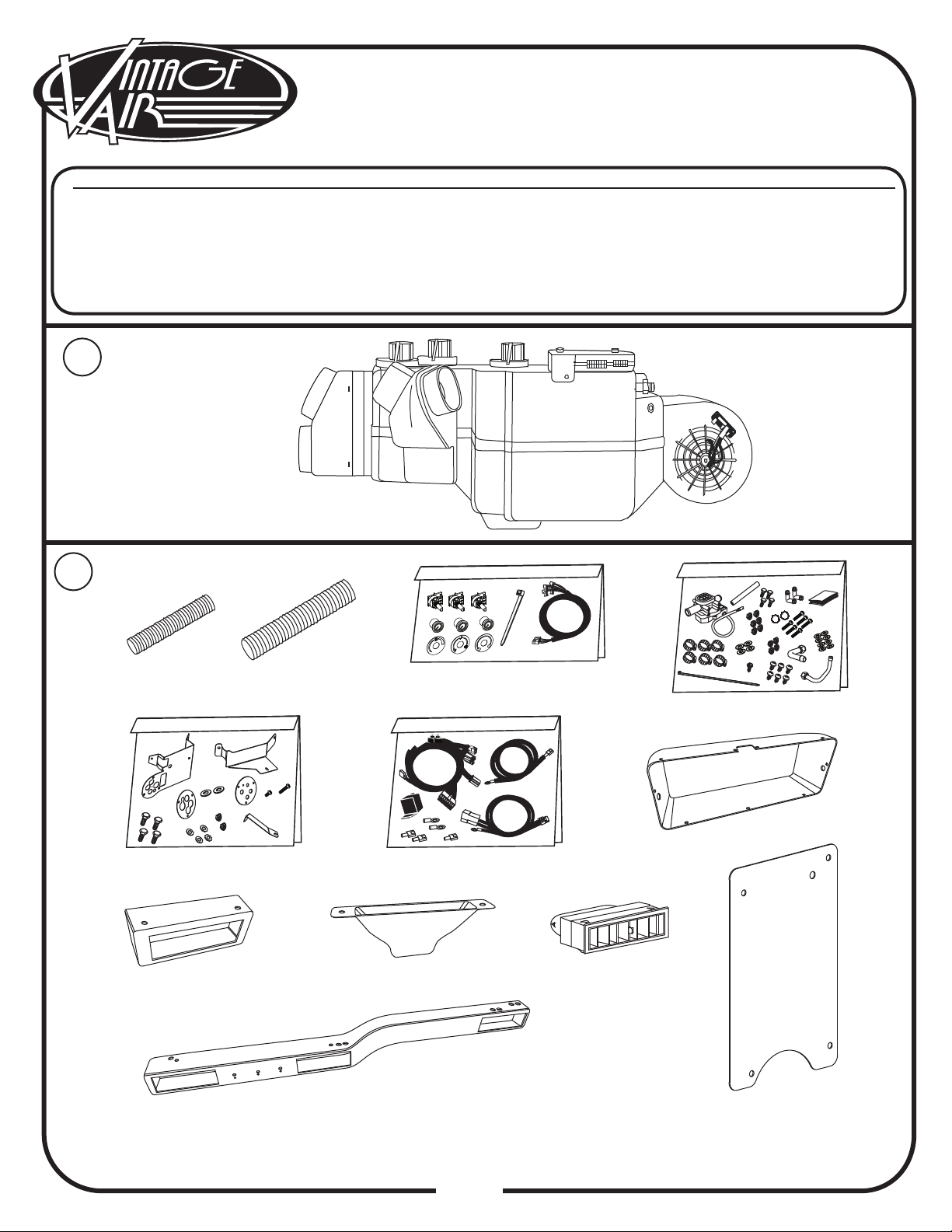
Packing List/Parts Disclaimer..................................................................................................
Information Page..................................................................................................................
Wiring Notice.......................................................................................................................
Engine & Passenger Compartment Disassembly........................................................................
Condenser Assembly and Installation, Compressor and Brackets, Pulleys, Defrost Duct
Installation..........................................................................................................................
Evaporator Assembly Preparation...........................................................................................
Firewall Bracket and Heater Hose Fitting Installation, Lubricating O-rings.....................................
A/C & Heater Hose Installation.............................................................................................
A/C & Heater Hose Installation (Cont.), Firewall Cover Installation............................................
Evaporator Installation........................................................................................................
Evaporator Installation (Cont.).............................................................................................
Rotary Pot Installation.........................................................................................................
Control Panel/Louver Bezel Assembly Installation....................................................................
Evaporator Installation (Final)..............................................................................................
Driver Side Under Dash Louver Installation, Heater Control Valve Installation.............................
A/C & Heater Hose Installation, V-8 Engines (Final)................................................................
A/C & Heater Hose Installation, 6-Cylinder Engines (Final).......................................................
Control Panel & Duct Hose Routing.......................................................................................
Wiring, Glove Box Installation..............................................................................................
Drain Hose Installation, Final Steps......................................................................................
Wiring Diagram..................................................................................................................
Gen IV Wiring Connection Instruction....................................................................................
Operation of Controls..........................................................................................................
Troubleshooting Guide.........................................................................................................
Troubleshooting Guide (Cont.)..............................................................................................
Packing List.......................................................................................................................
1
2
3
4
5
6
7
8
9
10
11
12
13
14
15
16
17
18
19
20
21
22
23
24
25
26
27
28
Table of Contents

3
www.vintageair.com
905460 REV D 01/12/17, PG 3 OF 28
Packing List:
Evaporator Kit (754561)
No.
1.
2.
Qty.
1
1
Part No.
744004-VUE
799002
Description
Gen IV Evaporator Sub Case, 4-Vent w/ 204 ECU
Accessory Kit, 1947-49 Chevrolet Pickup
** Before beginning installation, open all packages and check contents of shipment.
Please report any shortages directly to Vintage Air within 15 days. After 15 days,
Vintage Air will not be responsible for missing or damaged items.
NOTE: Images may not depict actual parts and quantities.
Refer to packing list for actual parts and quantities.
1
2
Gen IV Evaporator
Sub Case 4-Vent
w/ 204 ECU
744004-VUE
Accessory Kit
799002

4
www.vintageair.com
905460 REV D 01/12/17, PG 4 OF 28
Important Notice—Please Read
For Maximum System Performance, Vintage Air Recommends the Following:
New Vintage Air-supplied Sanden Compressor: No additional oil needed (Compressor is shipped with
proper oil charge).
All Other Compressors: Consult manufacturer (Some compressors are shipped dry and will need oil
added).
NOTE: Vintage Air systems are designed to operate with R134a refrigerant only.
Use of any other refrigerant could damage your A/C system and/or vehicle, and
possibly cause a fire, in addition to potentially voiding the warranties of the A/C
system and its components.
Refrigerant Capacities:
Vintage Air System: 1.8 lbs. (1 lb., 12 oz.) of R134a, charged by weight with a quality charging station or
scale. NOTE: Use of the proper type and amount of refrigerant is critical to system operation and
performance.
Other Systems: Consult manufacturer’s guidelines.
Lubricant Capacities:
Safety Switches
Service Info:
Protect Your Investment: Prior to assembly, it is critical that the compressor, evaporator, A/C hoses and
fittings, hardlines, condenser and receiver/drier remained capped. Removing caps prior to assembly will
allow moisture, insects and debris into the components, possibly leading to reduced performance and/or
premature failure of your A/C system. This is especially important with the receiver/drier.
Additionally, when caps are removed for assembly, BE CAREFUL! Some components are shipped under
pressure with dry nitrogen.
Evacuate the System for 35-45 Minutes: Ensure that system components (Drier, compressor, evaporator
and condenser) are at a temperature of at least 85° F. On a cool day, the components can be heated with a
heat gun or by running the engine with the heater on before evacuating. Leak check and charge to
specifications.
Your Vintage Air system is equipped with a binary pressure safety switch. A binary switch disengages the
compressor clutch in cases of extreme low pressure conditions (Refrigerant Loss) or excessively high head
pressure (406 PSI) to prevent compressor damage or hose rupture. A trinary switch combines Hi/Lo
pressure protection with an electric fan operation signal at 254 PSI, and should be substituted for use with
electric fans. Compressor safety switches are extremely important since an A/C system relies on refrigerant
to circulate lubricant.
Bolts Passing Through Cowl and/or Firewall:
To ensure a watertight seal between the passenger compartment and the vehicle exterior, for all bolts
passing through the cowl and/or firewall, Vintage Air recommends coating the threads with silicone prior to
installation.
Heater Hose (Not Included With This Kit):
Heater hose may be purchased from Vintage Air (Part# 31800-VUD) or your local parts retailer. Routing and
required length will vary based on installer preference.

5
www.vintageair.com
905460 REV D 01/12/17, PG 5 OF 28
Important Wiring Notice—Please Read
Some Vehicles May Have Had Some or All of Their Radio Interference Capacitors Removed.
There Should Be a Capacitor Found At Each of the Following Locations:
1. On the positive terminal of the ignition coil.
2. If there is a generator, on the armature terminal of the generator.
3. If there is a generator, on the battery terminal of the voltage regulator.
Most alternators have a capacitor installed internally to eliminate what is called “whining” as
the engine is revved. If whining is heard in the radio, or just to be extra cautious, a radio
interference capacitor can be added to the battery terminal of the alternator.
It is also important that the battery lead is in good shape and that the ground leads are not
compromised. There should be a heavy ground from the battery to the engine block, and
additional grounds to the body and chassis.
If these precautions are not observed, it is possible for voltage spikes to be present on the
battery leads. These spikes come from ignition systems, charging systems, and from
switching some of the vehicle’s other systems on and off. Modern computer-operated
equipment can be sensitive to voltage spikes on the power leads, which can cause unexpected
resets, strange behavior, and/or permanent damage.
Vintage Air strives to harden our products against these types of electrical noise, but there is
a point where a vehicle’s electrical system can be degraded so much that nothing can help.
Radio interference capacitors should be available at most auto and truck parts suppliers. They
typically are cylindrical in shape, a little over an inch long, a little over a half inch in diameter,
and they have a single lead coming from one end of the cylinder with a terminal on the end of
the wire, as well as a mounting clip which is screwed into a good ground on the vehicle. The
specific value of the capacitance is not too significant in comparison to ignition capacitors that
are matched with the coil to reduce pitting of the points.
Care must be taken, when installing the compressor lead, not to short it to ground.
The compressor lead must not be connected to a condenser fan or to any other
auxiliary device. Shorting to ground or connecting to a condenser fan or any other
auxiliary device may damage wiring, the compressor relay, and/or cause a
malfunction.
When installing ground leads on Gen IV systems, the blower control ground and ECU
ground must be connected directly to the negative battery post.
For proper system operation, the heater control valve must be connected to the
ECU.
•
•
•

6
www.vintageair.com
905460 REV D 01/12/17, PG 6 OF 28
Engine & Passenger Compartment
Disassembly
1.
2.
3.
4.
5.
6.
7.
8.
9.
10.
11.
12.
Disconnect battery. Ensure that the cable remains disconnected throughout the entire installation process.
NOTE: Battery is located under passenger oorboard.
Drain radiator.
Remove OEM heater hoses (discard).
Remove OEM heater/blower assembly if installed (discard) (See Photo 1, below).
Remove OEM heater wiring (discard).
Remove glove box door (retain).
Remove glove box (discard, but retain OEM screws).
Disconnect all wires and cables from OEM control panel (discard).
Disconnect all wires and cables from OEM heater control knobs (discard).
Remove OEM defrost ducts (discard).
Remove the defrost vent garnish/cover (retain) (See Photo 2, below).
Remove the round cover from the rewall (See Photo 3, below).
NOTE: Before starting the installation, check the function of the vehicle (horn, lights, etc.) for proper
operation, and study the instructions, illustrations, & diagrams.
Perform the Following:
Photo 1 Photo 2
Photo 3
Defrost Vent
Garnish/Cover
OEM Heater
Assembly
Firewall
Cover

7
www.vintageair.com
905460 REV D 01/12/17, PG 7 OF 28
Condenser Assembly and Installation
1.
2.
Refer to separate instructions included with the condenser kit to install the condenser.
Binary switch installation (Refer to condenser instructions).
Compressor and Brackets
1. Refer to separate instructions included with the bracket kit to install the compressor bracket.
Pulleys
1. In most instances, the belt lengths will remain the same.
Defrost Duct Installation
1.
2.
Using (2) #6 x 3/8” pan head screws, attach 18 inches of 2” duct hose to the passenger side defrost duct.
Attach the remainder of the duct hose to the driver side defrost duct.
Install the passenger and driver side defrost ducts into the dash using (4)#6 x 3/8” sheet metal screws, (2)
screws for each duct. Direct the passenger side defrost duct away from rewall, and toward the wiper arm.
Direct the driver side duct toward the rewall, and away from wiper arm (See Photos 4-7, below).
Photo 4
Photo 6
Photo 5
Photo 7
Duct Hose
Defrost
Duct
Defrost
Duct
Wiper
Arm
Wiper
Arm
Firewall
Driver Side Passenger Side
Firewall

8
www.vintageair.com
905460 REV D 01/12/17, PG 8 OF 28
Photo 8
Photo 10
Photo 11
Photo 9
Evaporator Assembly Preparation
1.
2.
Place the evaporator unit on a workbench. NOTE: To avoid scratching the unit, place it on a small piece
of carpet or similar surface, as you will be turning over the unit over many times while preparing
for the installation (See Photo 8, below).
Locate the #6 hose with 45° and straight female ttings. Temporarily (without an O-ring) connect the 45°
tting on the hose to the condenser core hardline (previously installed with the condenser kit), directing the
45° tting down to the depression on the inner fender inside the engine compartment as shown in Photo 9,
below. Next, direct the straight end of the hose to the hole on the rewall. Using a permanent marker, make
a mark on the side of the tting that faces the front of the truck (See Photos 10 & 11, below). NOTE: This
hose will be permanently connected to the evaporator while on the bench. Therefore, to prevent
twisting of the hose, it is necessary to orient the 45° tting by using the condenser core hardline as
a reference.
NOTE: Preparation of the evaporator assembly will be done on a workbench. Locate the evaporator
rewall bracket, hoses, heater hose ttings, O-rings, bolts, washers, lubricant, tie wrap and press
tape. As much as possible, always keep caps on hoses, hardlines and evaporator coils. The top of the
evaporator unit is the side with the control module.
Evaporator
Unit
Mark Fitting

9
www.vintageair.com
905460 REV D 01/12/17, PG 9 OF 28
Photo 12 Photo 13
Photo 14 Photo 14a
1.
2.
3.
Using a properly lubricated O-ring, install the lower heater hose tting (from intake) onto the evaporator (See
Photo 12 & Figure 1, below).
Install the rewall bracket onto the evaporator using (3) 1/4-20 x 1/2” bolts (supplied on evaporator unit)
(See Photos 12, 13, 14 & 14a, below). NOTE: When heater hoses are installed, they will pass through
the rewall bracket. Therefore, ensure that the heater hose ttings are centered in the 1.100”
holes on the bracket (See Photo 13, below).
Install the upper heater hose tting (to water pump) onto the evaporator with a properly lubricated O-ring
(See Photo 14 & Figure 1, below).
Firewall Bracket and
Heater Hose Fitting Installation
Lower
Heater Hose
Fitting
Firewall
Bracket
Center
Hose Fitting
in Hole
Figure ##
O-ring Installs
Over Male Insert
to Swaged Lip
O-ring
#6 O-ring
#8 O-ring #10 O-ring
O-ring
Supplied Oil
for O-rings
Male
Insert Female Nut
Hold With
This Wrench
Twist With
This Wrench
Lubricating O-rings
For a proper seal of fittings: Install supplied
O-rings as shown, and lubricate with supplied
oil.
NOTE: Standard torque specifications:
#6: 11 to 13 ft-lb.
#8: 15 to 20 ft-lb.
#10: 21 to 27 ft-lb.
Figure 1
1/4-20 x 1/2”
Bolt (2) 1/4-20 x 1/2”
Bolts
Upper
Heater Hose
Fitting

10
www.vintageair.com
905460 REV D 01/12/17, PG 10 OF 28
A/C & Heater Hose Installation
1.
2.
Using a properly lubricated O-ring, route the straight, previously marked, #6 A/C hose through the bottom 1”
hole on the evaporator rewall bracket, and connect it to the expansion valve, ensuring that the mark on the
tting points toward the rewall bracket/front of the truck (See Photos 15 & 16, below, and Figure 1, Page 9).
Using a properly lubricated O-ring, connect the 90° tting on the #10 A/C hose to the #10 suction port on the
evaporator. Direct the hose down and under the blower, and out of the remaining 1.30” hole in the evaporator
bracket at the 3 o’clock position. Use the supplied tie wrap to secure the hose to the Adel clamp located under
the blower (See Photos 17 & 18, below, and Figure 1, Page 9).
Photo 15 Photo 16
Photo 17
Photo 18
#6 Hose Routing
#6 Hose
Mark on
Fitting
Mark on
Fitting
Expansion
Valve
#10 Hose
#10 Suction
Port
Tie Wrap
Adel Clamp
#6 Hose

11
www.vintageair.com
905460 REV D 01/12/17, PG 11 OF 28
A/C & Heater Hose
Installation (Cont.)
1.
2.
Connect two pieces of heater hose approximately 45 inches long to the heater hose ttings. Using a small
amount of white grease on the heater hose ttings to make slipping the hoses on easier, push the hoses past
the plane of the bracket (See Photo 19, below). NOTE: Be sure not to loosen the tting connection nut
when pushing the hoses onto the barbed heater hose ttings. Hose clamps will be installed after the
evaporator is secured to the rewall, and the rubber boot and rewall ring have been installed.
Insulate the #10 A/C hose tting at the evaporator with press tape, covering all metal as shown in Photo 20,
below.
Photo 19
Photo 20
Photo 21
Press
Tape
#10
Hose
Push Hose
Past Plane
of Bracket
Firewall Cover Installation
1.
2.
3.
From the engine compartment, temporarily secure the rewall cover to the rewall using (2) 1/4-20 x 3/4”
bolts, (2) at washers and (2) nuts with star washers (See Photo 21, below).
Mark and drill (2) 5/16” holes through the upper and lower passenger side mounting holes in the rewall
cover (See Photo 21, below).
Remove the rewall cover, and apply a bead of silicone to the back side of the rewall cover at the edge of
all seams and bolt holes. Secure the rewall cover to the rewall using (4) 1/4-20 x 3/4” bolts, (4) 1/4” at
washers and (4) 1/4-20 nuts with star washers. NOTE: The remaining hole on the rewall cover will
be used to mount the evaporator unit (See Photo 21, below). Also note, paint will not adhere to
silicone.
Drill 5/16”
Hole
1/4-20 x 3/4” Bolt,
Washer and Nut with
Star Washer
Evaporator
Mounting Hole
1/4-20 x 3/4” Bolt,
Washer and Nut with
Star Washer
1/4-20 x 3/4” Bolt,
Washer and Nut with
Star Washer
1/4-20 x 3/4” Bolt,
Washer and Nut with
Star Washer
Drill 5/16”
Hole

12
www.vintageair.com
905460 REV D 01/12/17, PG 12 OF 28
Evaporator Installation
Photo 24
Photo 25
Photo 26
Photo 22
Photo 23
Studs
1/4-20 x 1”
Bolt and Washer
Clear Away
Insulation from
Bolt Holes
Rubber
Boot
Wiring Harness
Hole
1.
2.
3.
4.
Place the evaporator on the passenger side oorboard. Insert all hoses through the rewall hole (See Photo 22,
below).
OPTIONAL STEP: Remove the heads from (2) 1/4-20 x 1 ¼” bolts (not supplied) and insert them into the
evaporator rewall bracket. These studs will help align the evaporator bracket with the holes in the rewall
during installation (See Photo 23, below).
Lift the evaporator unit up under the dashboard. Using a 1/4-20 x 1” bolt and 1/4” washer, install the bolt
through the rewall cover and into the weld nut on the evaporator bracket. NOTE: Clear away the insulation
from the bolt holes on the rewall (See Photo 24, below). Temporarily install a bolt into the top hole
above the hoses on the rewall, and into the evaporator bracket. This will help hold the bracket to the rewall
while the rubber boot is being installed over the hoses.
Insert all four hoses through the provided rubber boot, pushing the boot 4” to 6” from the rewall (See Photos
25 & 26, below). NOTE: Soapy water may be used to ease installation of the hoses through the boot,
but be sure the A/C hoses are capped to prevent water from getting inside.
NOTE: To ensure a watertight seal between the passenger compartment and the vehicle exterior, for
all bolts passing through the rewall, Vintage Air recommends coating the threads with silicone prior
to installation.

13
www.vintageair.com
905460 REV D 01/12/17, PG 13 OF 28
Evaporator Installation (Cont.)
1.
2.
3.
4.
5.
6.
With the hoses installed through the rubber boot and the boot 4” to 6” from the rewall, feed the wiring
harness from inside the passenger compartment, through the rewall and through the rubber boot (See Photos
25 & 26, Page 12, and Photo 27, below). NOTE: Feed the heater control valve connector through the
boot rst. White grease may be used to ease installation.
Press the rubber boot against the evaporator rewall bracket. Install the rewall ring over the hoses. NOTE:
The service port cap on the #10 A/C hose tting must be temporarily removed to install the rewall
ring. Using (3) 1/4-20 x 1” bolts and (3) 1/4” washers, install the bolts through the rewall ring, rubber boot
and rewall, and into the weld nuts on the evaporator bracket. Tighten all bolts (See Photo 28, below).
Install (2) hose clamps on the heater hoses in the engine compartment at the rewall ring, ensuring that they
are seated past the barb on the tting (See Photo 28, below).
With the evaporator attached to the rewall, hold the evaporator cowl brace bracket up to the cowl and
evaporator to locate the approximate location of the 7/32” hole to be drilled from the top of the dash under the
defrost vent garnish/cover (See Photo 29, below). Measure 13/16” toward the driver side from the OEM hole
used to secure the defrost vent garnish/cover, and 1/2” down from the rubber windshield seal.
Attach the dash bracket and cowl brace bracket to the evaporator using (2) 1/4-20 x 1/2” bolts. The cowl brace
bracket mounts to the evaporator sharing the driver side dash bracket bolt (See Photo 30, below). Before fully
tightening the brackets to the evaporator, attach the cowl brace bracket to the cowl under the defrost garnish/
cover using the previously drilled hole with a 10-32 x 1/2” pan head screw, 3/16” at washer and 10-32 nut
with star washer (See Photo 31, below). Tighten the bracket bolts.
Reinstall the defrost vent garnish/cover to the dash.
Photo 28
Photo 27 Photo 29
Photo 31
Photo 30
Hose
Clamps
OEM
Hole
Rubber
Windshield Seal
1/4-20 x 1/2”
Bolt
1/4-20 x 1/2”
Bolt
Tighten
All Bolts
10-32 x 1/2” Bolt,
3/16” Washer, and
10-32 Nut with
Star Washer
Cowl Brace
Bracket
Cowl Brace
Bracket
Dash
Bracket
13/16”
1/2”

14
www.vintageair.com
905460 REV D 01/12/17, PG 14 OF 28
Rotary Pot Installation
1.
2.
Locate the (3) rotary pot assemblies, and install them into the louver bezel as shown below.
Tie wrap the wires to the rotary pots as shown below.
Blower Speed Mode Control Temperature
Control
Front View
(3) Rotary Pot
Knobs (3) Washers
Louver
Bezel
Temperature
Label
(3) Nuts
Mode
Label
Blower Speed
Label
Tie
Wrap
White
White/Red
Red
White
White/Yellow
Red
White
White/Green
Red
Top View

15
www.vintageair.com
905460 REV D 01/12/17, PG 15 OF 28
Control Panel/
Louver Bezel Assembly Installation
1. Before attaching the dash bracket to the dash, install the control panel/louver bezel assembly.
A. Locate the (2) OEM 5/16” bolts under the far passenger side of the dash. Remove the inner 5/16” bolt.
NOTE: This bolt will be reinstalled through the louver bezel in Step D, below. The bezel has a
clearance hole for the outer bolt.
B. Align the predrilled holes on the louver bezel with the (2) OEM mounting holes under the dash.
C. Secure the control panel/louver bezel assembly under the dash using (2) 10-32 x 3/4” pan head screws,
(4) 3/16” at washers and (2) 10-32 nuts with star washers (See Photos 32 & 33, below).
D. Reinstall the 5/16” bolt that was removed in Step A, above (See Photo 34, below).
E. Insert the louvers into the louver bezel.
Photo 32 Photo 33
Photo 34
10-32 x 3/4”
Pan Head Screw,
(2) 3/16” Flat Washers,
and 10-32 Nut with
Star Washer
10-32 x 3/4”
Pan Head Screw,
(2) 3/16” Flat Washers,
and 10-32 Nut with
Star Washer
Remove Inner 5/16” Bolt and
Reuse to Mount Control Panel/
Louver Bezel Assembly

16
www.vintageair.com
905460 REV D 01/12/17, PG 16 OF 28
Evaporator Installation (Final)
1.
2.
With the louver bezel mounted and the dash bracket secured to the evaporator, drill a 7/32” hole aligned with
the center of the slot on the dash bracket. Drill through the OEM dash brace, the bottom of the dash and the
top of the louver bezel. Attach the dash bracket to the dash through all drilled holes using a 10-32 x 1” pan
head screw, (2) 3/16” at washers, and a 10-32 nut with star washer (See Photo 35, below). NOTE: Install
this screw upward from the louver bezel.
Check that the evaporator unit is level at the passenger side of the drain pan (See Photo 36, below). If the unit
is not level, check to ensure installation steps were properly performed.
Photo 35 Photo 36
10-32 x 1”
Pan Head Screw,
(2) 3/16” Flat Washers,
and 10-32 Nut with
Star Washer
Drill 7/32”
Hole

17
www.vintageair.com
905460 REV D 01/12/17, PG 17 OF 28
Heater Control Valve Installation
Driver Side
Under Dash Louver Installation
1.
2.
1.
Align the inner hole on the driver side louver bezel with the OEM hole under the dash as shown in Photo 38,
below. Using the bezel’s outer hole as a template, mark and drill a hole into the bottom of the dash. Install
the driver side louver bezel using (2) 10-32 x 3/4” pan head screws, (4) 3/16” at washers and (2) 10-32
nuts with star washers (See Photo 38, below).
Insert the louvers into the louver housing (See Photo 39, below).
With the evaporator installed and (4) hoses exiting the rewall, cut the heater hose located at the 12 o’clock
position, 6 ½” from the rewall. Slide a hose clamp over the hose coming out of the rewall, push the
valve onto the hose and tighten the clamp. Connect the remaining hose to the other end of the valve, and
clamp the hose. NOTE: The arrow molded on the heater control valve body needs to point toward
the rewall (See Photo 40, below). Ideally, the valve should be mounted as shown in Photo 40,
below. However, the valve can be rolled 90° as shown in Photo 41, below. White grease may be
used on the valve barbs to ease installation.
Photo 38
Photo 39
Photo 40 Photo 41
(2) 10-32 x 3/4”
Pan Head Screws,
(4) 3/16” Flat Washers,
and (2) 10-32 Nuts
with Star Washers
OEM Hole
Mark And
Drill
Louver
Hose
Clamp
Molded Arrow
Toward Firewall
Heater Control
Valve
Heater Control
Valve

18
www.vintageair.com
905460 REV D 01/12/17, PG 18 OF 28
A/C & Heater Hose Installation,
V-8 Engines (Final)
1.
2.
3.
4.
5.
Using a properly lubricated O-ring, connect the #6 A/C hose to the #6 condenser hardline (See Photo 42,
below, and Figure 1, Page 9).
Using a properly lubricated O-ring, connect the #10 A/C hose to the compressor (See Photo 43, below, and
Figure 1, Page 9).
Using a properly lubricated O-ring, connect the straight tting on the #8 A/C hose to the #8 hardline from the
condenser. Connect the 135° tting to the compressor (See Photo 43, below, and Figure 1, Page 9).
Connect the heater hose from the heater control valve to the intake manifold. Secure with a hose clamp (See
Photo 43, below).
Connect the remaining heater hose to the water pump. Secure with a hose clamp (See Photo 43, below).
Photo 42
Photo 43
#6 Hose #8 Hose
Heater Hose
from Manifold
Heater Hose
to Water Pump
NOTE: Vintage Air systems require (2) 5/8” hose nipples (Not Supplied).

19
www.vintageair.com
905460 REV D 01/12/17, PG 19 OF 28
Photo 44 Photo 45
Photo 46
NOTE: Vintage Air systems require (2) 5/8” hose nipples (Not Supplied).
A/C & Heater Hose Installation,
6-Cylinder Engines (Final)
1.
2.
3.
4.
5.
Using a properly lubricated O-ring, connect the #6 A/C hose to the #6 condenser hardline (See Photo 42, Page
18, and Figure 1, Page 9).
From where it exits the rewall, route the #10 A/C hose to the compressor. Temporarily attach the 135° tting
to the compressor. Cut the hose to the proper length, and connect the hose to the compressor tting. Mark the
tting and hose to ensure proper positioning, and remove the tting from the compressor. Crimp the tting
onto the hose, and permanently connect to the compressor using a properly lubricated O-ring (See Photos 44
& 45, below, and Figure 1, Page 9).
Using a properly lubricated O-ring, connect the 90° tting on the #8 A/C hose to the #8 condenser hardline.
From there, route the #8 hose to the compressor. Temporarily attach the 135° tting to the compressor. Cut
the hose to the proper length, and connect the hose to the compressor tting. Mark the tting and hose to
ensure proper positioning, and remove the tting from the compressor. Crimp the tting onto the hose, and
permanently connect to the compressor using a properly lubricated O-ring (See Photos 44 & 45, below, and
Figure 1, Page 9).
Connect the heater hose from the heater control valve to the water neck. Secure with a hose clamp (See Photo
46, below).
Connect the remaining heater hose to the water pump. Secure with a hose clamp (See Photo 46, below).
NOTE: On 6-cylinder engine compartments, there are multiple possibilities for routing the #8 and #10
A/C hoses, depending the installer’s preference. For this reason, the #8 and #10 hoses are shipped
with ttings installed on one end only. The other end will need to be cut and crimped after routing has
been determined. For our installation, Vintage Air’s technicians routed the hoses beneath the engine,
securing them to the front frame crossmember with (2) #10 Adel clamps as shown below.
#10 Hose
Front Frame
Crossmember
135°
#10 Hose
135°
#8 Hose
Front of
Truck
Compressor
Oil Pan
(2) #10 Adel
Clamps
#8 Hose
Heater Hose from
Water Neck
Heater Hose to
Water Pump

20
www.vintageair.com
905460 REV D 01/12/17, PG 20 OF 28
Figure 2
Control Panel & Duct Hose Routing
1. Install the duct hoses as shown in Figure 2, below. NOTE: Do not route duct hoses over the ECU. Duct
hoses may sweat and drip onto/into the ECU, causing a malfunction.
Passenger Side
Defrost Duct
2” x 18”
Plug
From
Control
Wiring
Harness
232002-VUA
Plug
From
Wiring
Harness
232001-VUR
From
Control Panel
Driver Side
Defrost Duct
2” x 30”
Driver Side
Louver
2 ½” x 36”
Passenger Side
Louver
2 ½” x 48”
Driver Side
Center Louver
2 ½” x 13”
Passenger Side
Center Louver
2 ½” x 15”
Table of contents
Other Vintage Air Automobile Accessories manuals

Vintage Air
Vintage Air 474171 User manual

Vintage Air
Vintage Air 49306-VCL User manual

Vintage Air
Vintage Air 565072 User manual

Vintage Air
Vintage Air 561163 User manual

Vintage Air
Vintage Air 561072 User manual

Vintage Air
Vintage Air Steel-eez 15827-SCA User manual

Vintage Air
Vintage Air 751163 User manual

Vintage Air
Vintage Air 561191 User manual

Vintage Air
Vintage Air 1967-68 CAMARO w/o Factory Air Gen IV User manual

Vintage Air
Vintage Air Firebird 1969 User manual