Programmable Logic Controller Installation Guide
XGF-SOEA
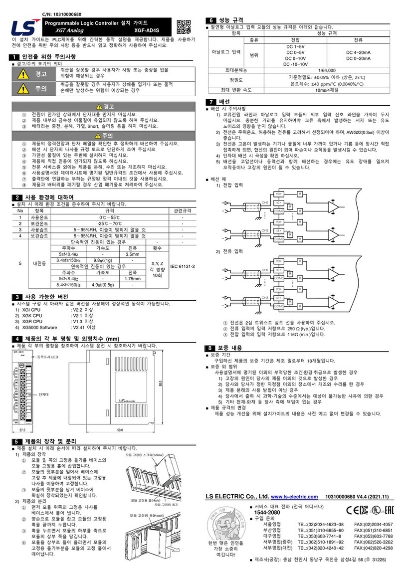
This installation guide provides simple function information of PLC control. Please read
carefully this data sheet and manuals before using products. Especially read safety
precautions and handle the products properly.
■ Meaning of warning and caution inscription
WARNING indicates a potentially hazardous situation which,
if not avoided, could result in death or serious injury.
CAUTION indicates a potentially hazardous situation which,
if not avoided, may result in minor or moderate injury.
It may also be used to alert against unsafe practices.
①Do not contact the terminals while the power is applied.
②Protect the product from being gone into by foreign metallic matter.
③Do not manipulate the battery(charge, disassemble, hitting, short, soldering).
①Be sure to check the rated voltage and terminal arrangement before wiring.
②When wiring, tighten the screw of terminal block with the specified torque range.
③Do not install the flammable things on surroundings.
④Do not use the PLC in the environment of direct vibration.
⑤Except expert service staff, do not disassemble or fix or modify the product.
⑥Use the PLC in an environment that meets the general specifications contained
in this datasheet.
⑦Be sure that external load does not exceed the rating of output module.
When disposing of PLC and battery, treat it as industrial waste.
■To install, observe the below conditions.
℃
℃
5 ~ 95%RH, non-condensing
5 ~ 95%RH, non-condensing
5 Vibration
Resistance
IEC 61131-2
each
direction
for
X, Y, Z
■ For system configuration, the following version is necessary.
1) XGI CPU : V3.8 or above
2) XGK CPU : V4.2 or above
3) XGR CPU : V2.5 or above
4) XG5000 Software : V3.68 or above
■This is front part of the CPU. Refer to each name when driving the system. For more
information, refer to user manual.
■ Here describes the method to attach each product to the base or remove it.
1) Attachment of product
①Slide the upper part of module to fix
to the base, and then fit it to the base
by using the module fixed screw.
②Pull the upper part of module to check
if it is installed to the base completely.
2) Detachment of product
①Loosen the fixed screws of the upper
part of module from the base.
②Hold the module by both hands and press
the fixed hook of module thoroughly.
③By pressing the hook, pull the upper
part of module from the axis of the lower
part of module.
④By lifting the module upward, remove
the fixed projection of module from the fixing hole.
■Performance specifications are as follows.
Event time Internal time: PLC time
External time: External time server time
Resolution(accuracy)
Internal time: 1ms(accuracy: ±2ms)
External time: 1ms(accuracy: ±0.5ms)
32 points(Sync/source type)
32 points input On/Off state U-device display
■ Installation of cable
1) Do not place AC power line near to the module’s external input signal line. It should
be farther than minimum 100mm between both lines in order not to be affected by
noise and magnetic field.
2) Cable shall be selected in due consideration of ambient temperature and allowable
current, whose size is not less than the max. cable standard of AWG22 (0.3㎟).
3) Do not place the cable too close to hot device and material or in direct contact with
oil for long, which will cause damage or abnormal operation due to short-circuit.
4) Check the polarity when wiring the terminal.
5) Wiring with high-voltage line or power line may produce inductive hindrance causing
abnormal operation or defect.
6) Use the cable of AWG24(0.3㎟) above with twisted and shielded when
communicating RS-422 by IRIG-B.
7) Determine the cable max. length and node by Timeserver specification of RS-
422(IRIG-B).
8) In case the signal ground of Timeserver isn’t isolated, use the RS-422 isolator
because of the noise. The transit delay of the isolator must be within 100㎲.
9) Do not use the isolator which has the function with analyzing the data signal and
sending it.
■ Wiring Example
1) The size of I/O device cable is limited to 0.3~2 mm2 but it is recommended to select
a size(0.3 mm2) to use conveniently
2) Please isolate input signal line from output signal line..
3) I/O signal lines should be wired 100mm and more away from high voltage/high
current main circuit cable.
4) Batch shield cable should be used and the PLC side should be grounded unless the
main circuit cable and power cable can’t be isolated.
5) When applying pipe-wiring, make sure to firmly ground the piping.
6) The output line of DC24V should be isolated from AC110V cable orAC220V cable.
■ Warranty period
18 months after the production date.
■ Scope of Warranty
18-month warranty is available except:
1) The troubles caused by improper condition, environment or treatment except the
instructions of LS ELECTRIC.
2) The troubles caused by external devices
3) The troubles caused by remodeling or repairing based on the user’s own discretion.
4) The troubles caused by improper usage of the product
5) The troubles caused by the reason which exceeded the expectation from science
and technology level when LS ELECTRIC manufactured the product
6) The troubles caused by natural disaster
■ Change in specifications
Product specifications are subject to change without notice due to continuous product
development and improvement.
LS ELECTRIC Co., Ltd. www.lselectric.co.kr 10310000989 V4.3 (2020.4)
•E-mail: automation@lselectric.co.kr
•Headquarter/Seoul Office
Tel: 82-2-2034-4033,4888,4703
•LS ELECTRIC Shanghai Office (China)
•LS ELECTRIC (Wuxi) Co., Ltd. (Wuxi, China)
•LS-ELECTRIC Vietnam Co., Ltd. (Hanoi, Vietnam)
•LS ELECTRIC Middle East FZE (Dubai, U.A.E.)
•LS ELECTRIC Europe B.V. (Hoofddorf, Netherlands)
•LS ELECTRIC Japan Co., Ltd. (Tokyo, Japan)
•LS ELECTRIC America Inc. (Chicago, USA)
•Factory: 56, Samseong 4-gil, Mokcheon-eup, Dongnam-gu, Cheonan-si, Chungcheongnam-
do, 31226, Korea
Parts name and Dimension (mm)
Performance Specifications
0989
