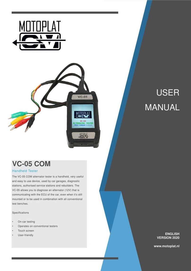
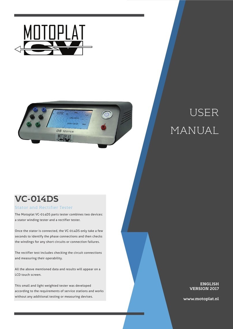
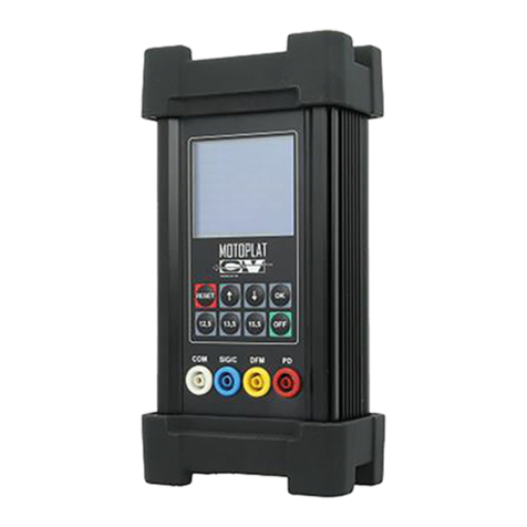
Motoplat VC-212RT User manual

USER
MANUAL
www.motoplat.nl
VC-212RT
The VC-212RT allows you to diagnose the operational
performance of a 12 and 24 volt alternator regulator.
VC-212RT regulator tester is a very useful and
easy to use device, used by car garages, diagnostic stations,
authorised service stations and rebuilders.
This small and light weighted tester was developed
according to the requirements of service stations and
works without any additional testing or measuring devises.
Parts Tester
ENGLISH
VERSION 2018

IMPORTANT INFORMATION
Safety Warning
Electrical devices should be installed and operated in such a way that all applicable safety requirements
are met. It is your responsibility as an installer to ensure that you idenfy the relevant safety standards and
comply with them. Failure to do so may result in damage to equipment and personal injury. In parcular,
you should study the contents of this guide carefully before installing or operang the equipment.
People who start using this product should review carefully this instrucon manual, or have had a training
from a qualied person.
The use of electrical equipment is enrely at your own risk and Motoplat® is under no circumstances
responsible for any incidental, consequenal or special damages of any kind whatsoever, including but not
limited to lost prots arising from or in any way connected with the use of the automated test equipment
or this manual.
The tester should be connected to a properly grounded outlet.
If the power cable is damaged, you must have it be replaced by the supplier or by another qualied person
in order to avoid dangerous situaons.
- Motoplat® -
Environment
The tester should be installed in an weather protected area where heat, humidity or any other climate
situaon can not damage the tester.
The tester should be installed on a level surface that is clear of debris and obstrucons.
Due to the open connecon of the tester to the test object, we strongly request to install and operate the
tester on a non-conducng surface.
Motoplat ®
Page 2

1 General Informaon
1.0 General informaon about the Motoplat VC-212RT tester 4
2 Specicaons and Installaon
2.0 Technical specicaons 5
2.1 Back panel 5
2.2 Front panel: Buons 6
2.3 Front panel: Connecons 6
3 Regulator Test
3.0 Displayed operaon modes 7
3.1 Buon meanings and results 8
3.2 Stator On/O buon 8
3.3 Over voltage check 8
3.4 Lamp 9
3.5 DFM or Feedback to ECU 9
3.6 Field 9
3.7 Through the voltage regulator 10
3.8 COM LIN/BSS 10
Index
4 Support
4.0 Contact informaon 11
Motoplat ®
Page 3

Secon 1 – General informaon
1.0 General informaon about Motoplat VC-212RT tester:
• Supports all control interfaces for modern voltage regulator such as LIN/BSS and PWM
• Automac detecon of a regulator load control of type, А or В.
• Checks the operaonal performance of a channel for monitoring the regulator.
• Simulates two outputs from alternator stator phases.
• Simulates overvoltage and alternator shutdown mode.
• Short circuit protecon.
• Following a set period of inacvity of the FLD inputs, the device will be switched o automacally.
Motoplat ®
Page 4

Secon 2 – Specicaons and Installaon
2.0 Technical specicaons:
General
Voltage (V) 12/24
Dimensions (MM) 252*158*79
Weight (KG) 1,71 (net. weight)
Motoplat ®
Page 5
No. Descripon
1Cable connecon
2Fuse (15A / 125 VAC)
2.1 Back panel:
Check if the fuse is ghtened proparly.
If the fuse need to be replaced, turn it counter clock wise to remove it from the tester.

2.2 Front panel : Buons
Descripon Explanaon
13V / 14V / 15V simulaon of commands for seng the corresponding regulator voltage at the RC
output. Operable in all modes excluding LAMP.
OV Simulaon of an overvoltage. Press again to turn o this mode.
ST o Switches o stator signals at the ST outputs. Simulaon of an alternator belt rip.
Press again to switch on the signals. The ST outputs are acvated on startup.
Mode Selecon of a regulator control mode: LAMP, SIG, COM, RLO, P-D (D), C, L-F (L).
On/O On/o switch. Selecon of the regulator voltage 24 V (in the LAMP mode only) and
return to 12 V are performed by holding this buon down. The device is in the 12 V
mode on startup.
Motoplat ®
Page 6
Descripon Explanaon
B- Negave
B+ Posive
FLD Regulator load. The outputs are connected to both brushes in any order. While con-
necng a brushless regulator, the other terminal must be connected to + or -.
ST Stator signal outputs with a phase shi of 120°.
L Control lamp input
M Monitor input for connecng terminals P, FR, DFM, М, Ll.
RC Regulator control output for connecon to the terminals SIG, СОМ, RLO, P-D (D), С,
L-F (L).
2.3 Front panel : Connecons

Motoplat ®
Page 7
3.0 Displayed operaon modes:
LAMP mode
P-D mode (Mazda, KIA)
SIG mode (Ford,Landrover and Motorcra)
L-F mode (General Motors/Opel)
The following device operang modes can be selected by pressing buon MODE:
C mode (Nissan)
RLO mode (Toyota)
COM mode(LIN/BSS)
Secon 2 – Regulator Test

Page 8
Motoplat ®
3.1 Buon meanings and results:
When simulang commands for seng regulator voltage by pressing buons 13 V, 14 V and 15 V, the
following messages are displayed respecvely:
Result: the regulator should react to the voltage commands.
3.2 Stator On/O buon:
When alternator stator signals are switched o/on by pressing the ST OFF buon the following messages
are displayed:
Result: the regulator should not charge any more.
3.3 Over voltage check:
When simulaon of overvoltage is switched o/on by pressing the OV buon the following messages are
displayed:
Result: the regulator shows the maximum regulated voltage.

Page 9
Motoplat ®
3.4 Lamp:
The following icons are displayed for the L (LAMP) input:
Result: Baery lamp ON is NOT charging mode and Baery lamp OFF is charging mode.
3.5 DFM or Feedback to ECU:
Signal frequency and duty cycle at the input M (DFM) are displayed as follows:
Result: should show a percentage and/or frequency
3.6 Field:
Parameters of the acve brush FLD are displayed as follows:
Switching mode of the regulator switching element is displayed as follows.
“A” Circuit: (low side) one side of the eld is connected to posive the negave side is suppliedthrough the
regulator.
“B” Circuit: (high side) one side of the eld isconnected to ground, the posive side is supplied
Not charging: Charging

Page 10
Motoplat ®
3.7 Through the voltage regulator:
DC- switching (circuit A): DC+ switching (circuit B):
Result: regulator should charge
3.8 COM LIN/BSS:
If there is no connecon to the regulator in the СОМ mode, a “No connecon” message is displayed:
When LIN or BSS protocols are detected, the following messages are displayed:
respecvely followed by a regulator idener.
For LIN protocol, interface operang speeds used by the regulator are displayed aer the idener:
Where L, M and H corresponds to low, medium and high values respecvely.
Also known as baud rate or communicaon speed.

Page 11
Motoplat ®
Reference connecon of the regulator to the tester:
COM mode
Protocol LIN, type A, idener 33. The
regulator operates at three speeds.
DFM from the regulator, 9% rotor load
Mechanical error (no stator signal)
FLD parameters
Switching mode of the eld
When the stator signal is turned on by pressing the ST OFF buon, the regulator starts working, goes into
the operang mode and sets a voltage value.
As seen, an actual voltage value complies with the set value of:
Result: the regulator is working properly. No errors.

www.motoplat.nl
Stichtse Kade 47c
1244NV ‘s-Graveland, The Netherlands
+ 31 (0)35 656 3180
www.motoplat.nl
MOTOPLAT CV
Contact Information
Table of contents
Other Motoplat Test Equipment manuals