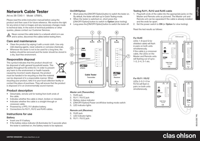
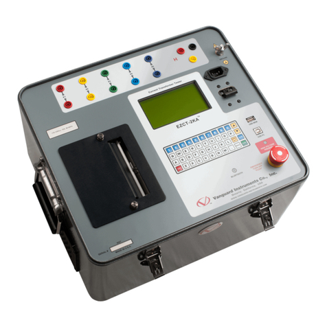
T&R KV30-40 Operating instructions

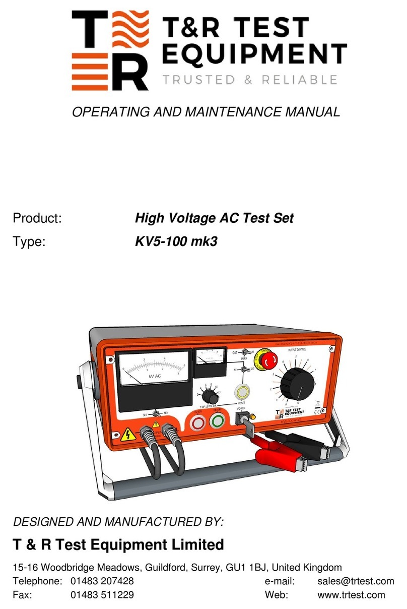
OPERATING AND MAINTENANCE MANUAL
Product: High Voltage AC Test Set
Type: KV30-40
KV15-18
DESIGNED AND MANUFACTURED BY:
T & R Test Equipment Limited
Keens Lane, Worplesdon, Guildford, Surrey, GU3 3LS, United Kingdom
Telephone: 01483 235757 e-mail: [email protected]
Fax.: 01483 235759 Web: www.trtest.com

2

3
GENERAL SAFETY STATEMENT
The following safety precautions should be reviewed to avoid injury to the user and damage to the
product (and other products connected to it). To avoid potential hazards only use this product as
specified.
Only suitably qualified personnel should use this equipment. Servicing of this product should only
be carried out by suitably qualified service personnel.
Hazardous voltages and currents are present on the outputs of this unit.
To Avoid Fire Hazards and Personal Injury
Use the correct power supply lead. Only use a suitably rated and approved power supply lead for
the country of use.
Ensure that systems that the unit is to be connected to are dead.
Do not connect and disconnect leads whilst outputs are switched on.
Ensure that the product is grounded. To avoid electric shock it is essential that the grounding
conductor is connected to the earth ground. If an additional earth terminal is provided on the
equipment that may be connected to a local earth. Ensure that the product is properly grounded
before making any connections to inputs or outputs.
Terminal ratings must be observed to prevent fire hazards and risk of injury to the operator.
Consult the product manual for ratings information before making connections to any terminal.
It is ESSENTIAL to consult the product manual for rating information before making any
connection to a terminal or terminal group marked with a warning triangle.
Only use fuses of a type and rating specified for this product.
Do not operate the unit out of its case or with any covers or panels removed.
Do not touch exposed connections and components when power is present.
Do not operate the product if any damage is suspected. Refer the unit to qualified service
personnel to be checked.
Do not operate the unit in wet or damp conditions
Do not operate the unit in an explosive atmosphere
If any further queries occur regarding the usage and maintenance of the
equipment detailed in this manual, please refer these to the supplier of the
equipment in the first case or to:
T & R Test Equipment Limited

4

5
CONTENTS
1. Description of Equipment
2. Operating Procedures
3. Maintenance Instructions
4. Standard Accessories
5. Overall Performance Specification
6. Calibration Results
7. Test Certificate
8. Revision

6

7
1. DESCRIPTION OF EQUIPMENT
1.1 Electrical Specification
1.2 Output Voltage Control
1.3 Overload Protection
1.4 Metering
1.5 Construction

8
1.1 Electrical Specification
1.1.1 The supply voltage will be as follows:
220/240V 1 phase 50/60Hz+10%
115V 1 phase 50/60Hz +10% -6%
1.1.2 The minimum supply requirements are 1200VA:
1.1.3 The output voltage, current and duty cycle are as follows:
Output Voltage Output Current 1 Output Current 2
KV30-40 30kV 20mA 40mA
KV15-80 15kV 40mA 80mA
Output current 1 is the continuous current rating.
Output current 2 is based on a duty cycle of 5 minutes ON load followed
by 15 minutes OFF load.
1.1.4 One side of the high voltage transformer output is connected to the earth system of
the equipment.
1.1.5 System Interlock:
The equipment is fitted with a zero volt interlock system on the controlling regulator.
This interlock prevents the output being energised unless the controlling regulator is in
the minimum output position.
1.1.6 An earthing hook is provided which is stored in the lid of the test set.

9
1.2 Output Voltage Control
1.2.1 The output is controlled from zero by means of a regulating transformer. The transformer
is operated by means of a control knob which is located on the front panel of the control
unit. To increase the output voltage the knob is turned in a clockwise direction.

10
1.3 Overload Protection
1.3.1 The equipment is fitted with fixed and variable overload protection circuits as standard.
1.3.2 Fixed overload
The fixed overload protection system senses any rapid increase in the load current which
exceeds approximately 120% of the full load current in the high voltage circuit. The
circuit will respond more quickly to low impedance faults.
1.3.3 Variable overload
The variable overload protection system senses current changes in the high voltage
circuit. The trip level is adjusted by means of a selector switch on the front panel of the
control unit. The switch allows the level to be adjusted from 10-110% of normal full
current in eleven steps.
The circuit will activate when the load current exceeds that set by the trip level selector
switch.
The circuit will respond to more slowly changing levels of load current.
IMPORTANT NOTE: The variable overload trip circuit does not limit the output
current on short circuit.

11
1.4 Metering
1.4.1 The equipment is provided with the following metering:
a. A moving coil dual range kilovoltmeter monitoring the output voltage from the
equipment.
b. A moving coil single range milliammeter monitoring the secondary current of the
highvoltage transformer.

12
1.5 Construction
1.5.1 The equipment is housed in a robust case with recessed carrying handles. All the
controls and metering are located on the front panel together with all external connections.

13
2. OPERATION
2.1 Connections
2.2 Front Panel Functions
2.3 Method of Operation

14
2.1 Connections (See Figure 1)
2.1.1 The input lead on the control unit should be connected to a suitable three pin plug.
2.1.2 Connect the earth lead from a reliable efficient earth to the earth terminal on the
equipment.
2.1.3 Connect the earth hook lead to the earth terminal on the test set and place the hook
on the test object's high voltage terminal.
2.1.4 IMPORTANT
The output cable is only partially screened. it is therefore essential that the minimum
clearance of 20cm be maintained around the unscreened portion of the output cable.
(See Figure 1)

15
Figure 1 Connection showing earthed test object – before start of test
screened part of HV cable
supply cable earth
screen limit and stress relief
HV test set
unscreened part of HV cable
earth return
test object
earth stick
IMPORTANT: There must be 20cm minimum clearance between the
unscreened section of HV output cable and earth.
Note:-The test object is shown earthed via the earth stick as it should be between tests
and before any adjustment to the test object. The earth stick should be removed
from the test object before the test, and replaced after the test is complete.

16
2.2 Front Panel Control Functions
2.2.1 ITEM FUNCTION
a. Power ON/OFF switch To isolate equipment from the mains supply.
Key operated
b. Power ON lamp To indicate that the supply is connected to the
equipment, power switch is closed andthe supply
fuse is intact.
c. H V OFF illuminated Indicates HV output is OFF when lit. Switches
push-button (Green) OFF HV output when pressed.
d. HV ON illuminated Indicates HV output is ON when lit. Switches
push-button (Red) ON HV output when pressed.
e. Trip level mA switch Selects output current trip level in mA.
f. Trip reset illuminated Indicates variable overload circuit has activated
push-button (Amber) when lit. Resets and arms circuit when pressed.
g. Supply voltage selector Selects desired input supply voltage either
240V, 220V or 115V.
h. Interlock 24V~ (Option) User interlock socket 24V~, see Section 1.1.5

17
Front Panel Layout
EARTH RATING
MAINS FUSE
IN VOLTAGE SELECTOR
DANGER HIGH VOLTAGE
Ma kV
TRIP
X 0.5 X 1
MILLIAMPS RESET ÷10 KV RANGE
ON
HV OUTPUT
OFF
0 100%
POWER OUTPUT CONTROL
TYPE KV30-40 T&R TEST EQUIPMENT
g
fe
d
c
ab

18
2.3 Method of Operation
2.3. 1 Connect the equipment as described in Section 2.1.
2.3. 2 Remove the power switch operating key before connecting the equipment to the main
supply. This will ensure the equipment is in the OFF position as the key is only
removable in that position. Thekey is trapped in the ON position.
2.3. 3 Once the equipment is connected to the main supply the key operated switch can be
moved to the ON position. The following will now occur:
a. Power ON lamp will be lit
b. HV OFF lamp will be lit
c. Thevariable overload reset lamp will be lit
2.3. 4 Press the variable overload reset push-button thus arming the circuit. The indicator lamp
in the reset push-button will go out thus indicating that the circuit is armed.
2.3. 5 Select the desired voltage range on the kV meter and set the desired overload mA trip
level.
2.3. 6 Before commencing testing ensure that the regulator is in the fully anticlockwise position.
2.3. 7 Depress HV ON push-button and this will close the internal circuit breaker The HV OFF
lamp will extinguish and the HV ON lamp will be lit. The output voltage can now be
increased to the desired level as indicated on the kV meter.
2.3. 8 In the event of a test object failure the HV output will be automatically switched off bythe
protection system.
2.3. 9 When the test is completed, turn the regulator control knob fully anti-clockwise and switch
off the HV output and then the main supply.
2.3.10 Before disconnecting the test object ensure the HV connection is grounded using the
earthing stick provided.

19
3. MAINTENANCE
3.1 The switches and contactors should be occasionally examined for signs of wear and
contact erosion. Badly eroded contacts should be replaced immediately.
3.2 The voltage regulator should be regularly examined, particularly in respect of the brushes,
in order that the latter may be replaced before excessive wear has taken place.
3.3 The intervals between inspection and renewal of the brushes will depend upon the
amount of usage. However, it should be remembered that extensive damage to the
voltage regulator can result if the brushes are allowed to wear away to such an extent
that a loss of brush pressure occurs thus causing arcing.
3.4 The occasional wiping of the regulator track with an alcohol moistened rag is
recommended. If however the track is badly corroded it should be cleaned with very
fine sand paper ensuring a flat surface is restored. Remove particles with a fine brush
and finally cleanse with an alcohol moistened brush.
3.5 The equipment's output cable should be kept clean and inspected regularly for damage.
This applies especially to the unscreened portion of the output cable.
3.6 To remove the set from its case. The following procedure must adopted:
a. Remove all four M5 posidrive fixing screws from the underside of the set.
(centre of rubber feet)
b. Place the set in the normal operating position, i.e. with the control panel horizontal.
c. Remove all six panel fixing screws.(M6 posidrive screws, nylon washers)
d.Remove the two M6 dome nuts from the lifting positions.
e. Screw on to the exposed threads of the lifting positions the tommy bars provided.
f. The set can now be lifted from the case taking care not to foul the supporting
brackets.

20
4. STANDARD ACCESSORIES
4.1 Spare fuses supplied
a. 1 off T5A 1¼ inch
b. 1 off F10A 1¼ inch
4.2 The following items are provided with the equipment:
a. Mains input lead.
b. 2 keys (for mains ON/OFF switch).
c. 5 metre earth lead fitted with clip and tag.
d.Type ES30-40 earthing stick.
e. 2 tommy bars.
f. Operating & Maintenance Manual.
This manual suits for next models
1
Table of contents
Other T&R Test Equipment manuals

T&R
T&R PT18-10 mk2 Operating instructions
T&R
T&R KV30-40D mk3 Operating instructions

T&R
T&R 200A-3PH mk2 Operating instructions
T&R
T&R PCU2 mk5 Operating instructions

T&R
T&R PT30-10 mk2 Operating instructions

T&R
T&R TPT9000 Operating instructions
T&R
T&R PT30-10 Operating instructions
T&R
T&R KV mk2 Series Operating instructions
T&R
T&R PT15-10s Operating instructions
T&R
T&R KV6-80 Operating instructions
