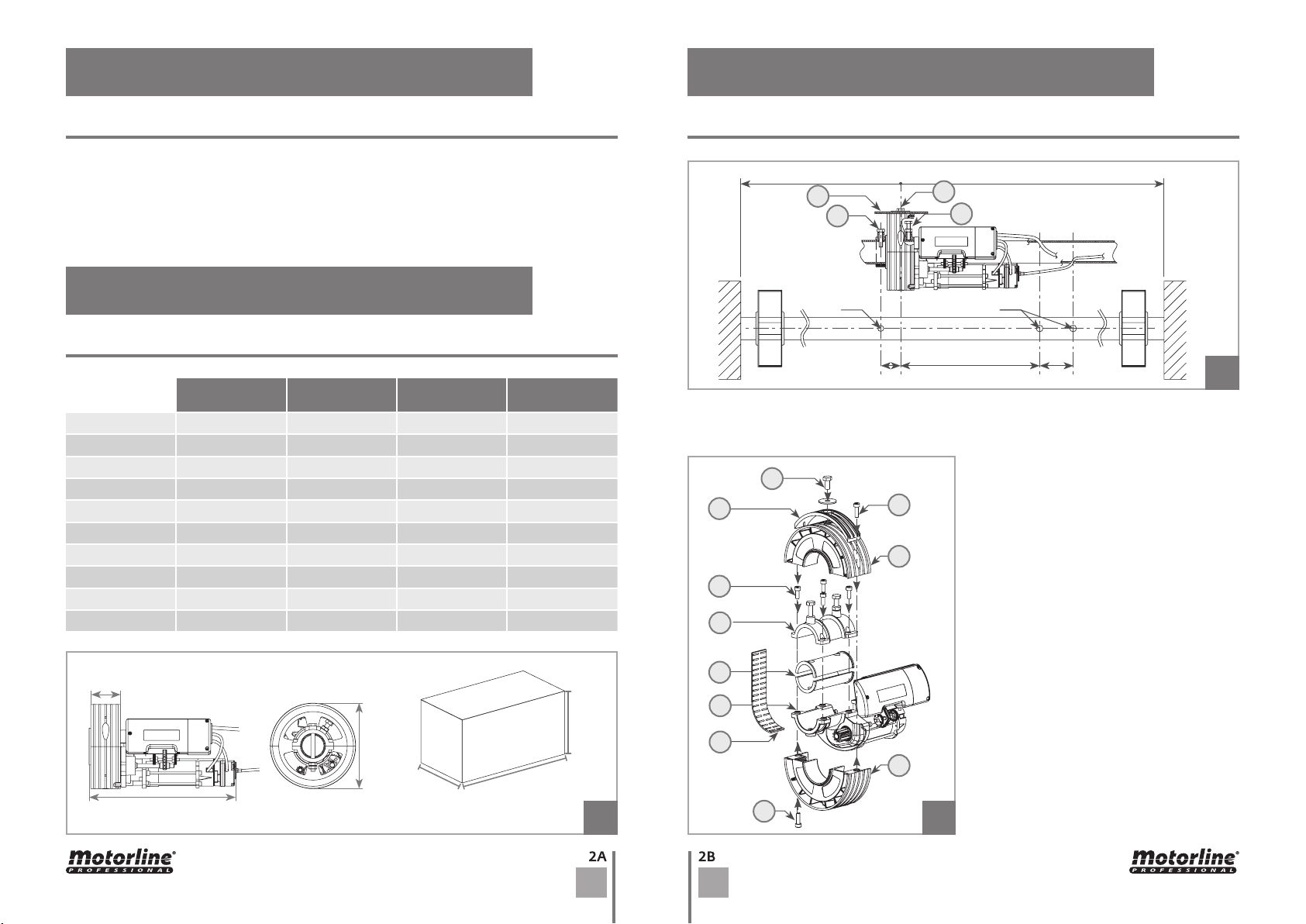
Motorline professional ROLLING Series Use and care manual

v2.1
REV. 11/2014
EN
USER'S AND INSTALLER'S MANUAL
ROLLING | ROLLING SP

1B
2A
4B
2B
5A
ENEN
ATTENTION:
• To ensure the safety of people, it is important that you read all the following
instructions. Incorrect installation or incorrect use of the product can cause physical
injury and material damage.
• Keep these instructions in a safe place for future reference.
• This product was designed and produced strictly for the use indicated in this manual.
Any other use, not expressly indicated here, could compromise the good condition/
operation of the product and/or be a source of danger.
• ELECTROCELOS SA is not responsible for the improper use of the product, or other use
than that for which it was designed.
• ELECTROCELOS SA is not responsible if safety standards were not taken into account
when installing the equipment, or for any deformation that may occur to it.
• ELECTROCELOS SA is not responsible for the safety and proper operation when using
components not sold by them.
• Do not make any modifications to the operator components and / or their accessories.
• Before installation unplug the automatism from the source of power.
• The installer must inform the client how to handle the product in case of emergency
and provide this manual to user.
• Keep remote controls away from children, to prevent the automated system from be-
ing activated involuntarily.
• The customer shall not, under any circumstances, attempt to repair or tune the oper-
ator. Must call qualified technician only.
• Connect the automatism to a 230V plug with ground wire.
• Operator for indoor use.
• Do not install the gearmotor in presence of fumes or inflammable gas.
• The mechanical parts must conform to the provisions of standard EN 12604 and EN 12605.
• The installation must conform to standards EN 12453 and EN 12445.
• The main power supply of the automated system must be fitted with an all-pole switch
with contact opening distance of 3mm. Use of a 6 A thermal breaker with all-pole circuit
break is recommended.
• The safety devices (photocells , etc.) protect any danger areas against mechanical move-
ment risks, such as crushing, dragging, and shearing.
• Use of at least one indicator-light is recommended for every system, as well as a warning
sign, in addition to the safety devices.
• Do not command more than one gearmotor with each button.
STANDARDS TO FOLLOW
TECHNICAL SPECIFICATIONS
INSTALLATION OF THE ELECTROBRAKE
INSTALLATION INSTRUCTIONS
GEAR MOTOR WITH SAFETY DEVICE
01. SAFETY INSTRUCTIONS
02. THE AUTOMATISM
INDEX STANDARDS TO FOLLOW
00. CONTENT 01. SAFETY INSTRUCTIONS

03
Ø10
50
"L/2"
500 50
Ø12
B
C
E
C
K
H
I
G
G
E
F
D
D
L
A
268mm
475mm
258mm
225mm
368mm
72mm
02
01
ENEN
• Do not allow children or adults to stay near the product while it is operating.
• Transit is permitted only when the automated system is fully openned.
• Maintenance: check at least every 6 months the efficiency of the system.
• Anything not expressly specified in these instructions is not permitted.
STANDARDS TO FOLLOW INSTALLATION INSTRUCTIONS
01. SAFETY INSTRUCTIONS 02. THE AUTOMATISM
TECHNICAL SPECIFICATIONS
02. THE AUTOMATISM
01 • Close the rolling shutter.
02 • Make 3 holes in the shutter's tube as shown in image 02.
03 • Remove the M10 screw (C) from the crown of the gearmotor (figure 03).
04 • Remove the two semi-crown (D)
unscrewing the two M8 screws (E) as
shown in figure 03.
05 • Carefully remove the plastic band
with rolls (F) avoiding heavy folds that
would cause the spillage of the rolls.
06 • Separate the two elements of the
gearmotor (G) unscrewing the four M8
screws (H).
07 • In case the diameter of the tube is
inferior to 60mm, use the reductions Ø33
/ Ø42 / Ø48 (I) positioning them on the
10mm hole drilled previously (figure 02).
08 • Assemble on the tube of the shutter
the two elements of the gearmotor (G)
using the four M8 screws (H) removed
before.
09 • Fasten the M10 screw (A) without
hexagon nut, screwing it inside the hole
10mm (figure 02).
ROLLING
120 | 120SP
ROLLING
160 | 160SP
ROLLING
360 | 360SP
ROLLING380
Torque 120Nm 155Nm 420Nm 450Nm
Lifts 120Kg 160Kg 360Kg 380Kg
Maximum height 6m 6m 6m 6m
RPM 10 10 8 8
Capacitor 16µF 20µF 20µF (x2) 20µF (x2)
Power supply 230V 50/60Hz 230V 50/60Hz 230V 50/60Hz 230V 50/60Hz
Consumption 2,2A 2,7A 5,4A 5,8A
Power 460W 630W 1260W 1330W
Termal protection 4min 4min 4min 4min
Weight 7 kg 8 kg 16 kg 17 kg

04 M
M
05
06
04
ENEN
02. THE AUTOMATISM 02. THE AUTOMATISM
INSTALLATION INSTRUCTIONS INSTALLATION INSTRUCTIONS
15 • Remove the limit-switch board's cover.
16 • Make the electrical connections as shown in figure 04 passing the 4x1mm cable
supplied, inside the shutter shaft avoiding any contact with the rotating parts (figure
02). In presence of motor with electrobrake, insert the sheath of the brake inside the
other hole Ø12.
17 • Connect the terminal block (M) of the power wire to the limit switch respecting the
right direction (figure 06). Fasten the terminal block through the four screws.
Motor
Motor
Electrobrake
Electrobrake
Capacitor
Earth
Power supply
230V
Switch
Switch
Power supply
230V
10 • Tighten the M10 screw with nut (B) in order to block the gearmotor on the shaft.
11 • Install the plastic band with rolls (F) in its appropriate place.
12 • Install the two semi-crown (D) fixing them with the two M8 screws (E). In presence
of spring boxes diameter 220 mms use the adapter (K) (figure 03).
13 • Make 12 mm hole in the last element of the shutter (L), aligned with the M10 hole
existing on the crown motor.
14 • Place the last element of the shutter on the motor and secure it through the screw
M10 (C) with washer (figure 03).
Capacitor
Common
Brown
Earth
Black
Brown
Black
Common
Common
Brown
Black ROLLING SP
ROLLING SP
ROLLING SP
ROLLING
ROLLING
ROLLING

P
Q2
Q2
Q1
Q1
2
2
1
1
08
09
10
T
R
V
SU
O
ON
07
N
ENEN
02. THE AUTOMATISM
INSTALLATION INSTRUCTIONS
20 • Rotate the plastic washer (Q1) by hand until you hear the click of the microswitch
1 (down regulation completed).
21 • Rotate the other plastic washer (Q2) towards the microswitch 2 (up). Give tension
to the motor through an electric command and verify if the shutter, climbing, stops in
desired point. Adjustments of the position can be effected acting always on the same
plastic washer and operating through electric command.
22 • Should the shutter need to be installed contrary to the description in figure 02, the
steps described above should be carried out to the contrary as microswitch 2 will stop
the closing and microswitch 1 will stop the opening.
23 • Fasten the counternuts after adjusting the limit-switch washers.
19 • After having installed the mechanical parts and electrical connections, proceed to
the regulation of the limit-switches as shown in figure 09.
Note • In Rolling SP, please see image 10 of next page.
INSTALLATION OF THE ELECTROBRAKE
01 • Insert the brake ( R ) on the back of the electrical motor as shown in figure 10.
02 • Fixing the electrobrake (S) to the motor using the screws M5x50 (U).
03 • Remove the bridge (T) from the limit switch.
Do not damage the bridge pulling on the wire and keep it for future use.
04 • Connect the electric cables (V) of the brake to the terminal of the limit switch.
05 • Close the limit switch using the plastic cover (N) (figure 07).
18 • Close the limit switch through the
plastic cover (N) and then fasten with
the two screws (O), checking the correct
disposition of the cables (figure 07). In
presence of motor with electrobrake,
remove the pin (P) on the plastic cover
(figure 08).
02. THE AUTOMATISM
INSTALLATION INSTRUCTIONS
ROLLING
ROLLING SP
ROLLING SP
ROLLING
ROLLING

13
14
WNC
COM
M
12
Z
90º
Ø10,5 90º
11
10
ENEN
02. THE AUTOMATISM 02. THE AUTOMATISM
GEAR MOTOR WITH SAFETY DEVICEINSTALLATION OF THE ELECTROBRAKE
03 • The downward run of the roller shutter
shall ben consistent with the downward
run of the safety brake. Place the gear
motor as shown in 13.
04 • For microswitch versions, connect the
micro switch’s cable (W) in series to the fee
ding cable (common) of the gearmotor (fi-
gure 14).
02 • After assembled the two elements of
the gearmotor (G), check that the pawl (Z)
is in the highest position perpendicular
to the rolling shutter axis (figure 12).
GEAR MOTOR WITH SAFETY DEVICE
Gear motor with safety device carried out to the stop the free fall of roller shutters and at
the same time, in microswitch versions, to interrupt the motoreductor’s feeding.
01 • Effect on the tube of the shutter a pas
sing perforation Ø10 perpendicular to the
axis (figure11).
Common
Brown
Black
Motor
Electrobrake
Capacitor
Switch
Power supply
230V
Shunt
Note • When installing the electrobrake on Rolling SP,rmove the shunt visible on image
10 ande make the connections of the electrobrake as visible on image 04.
Brown
Black
Common
ROLLING SP
This manual suits for next models
8
Table of contents
Other Motorline professional Engine manuals

Motorline professional
Motorline professional Rolling SP Use and care manual

Motorline professional
Motorline professional TUB10R Instruction Manual

Motorline professional
Motorline professional TUB10R Instruction Manual

Motorline professional
Motorline professional BRAVO500 Use and care manual

Motorline professional
Motorline professional KPORTB75 Instruction Manual