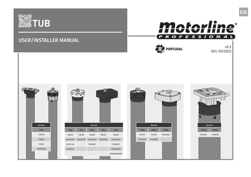
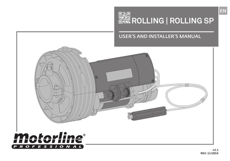
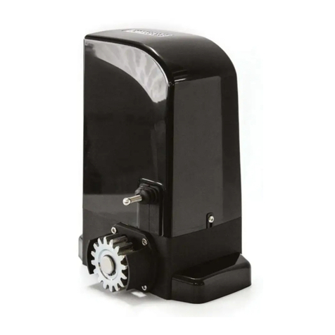
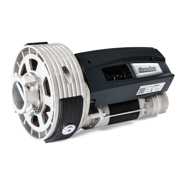
Motorline professional TUB10R Instruction Manual

v6.2
REV. 10/2020
Ø35 mm
20kg
TUB10R
TUB20R
TUB20
TUB20EFRA
Ø59 mm
140kg 180kg 200kg
TUB140 TUB180 TUB200R2
TUB140MT TUB180MT
Ø92 mm
300kg 600kg
TUB300E TUB600E
Ø45 mm
25kg 35kg 50kg 70kg 90kg
TUB25E TUB35E TUB50E TUB70E TUB90E
TUB25EFRA TUB35EFRA
TUB50EFRA
TUB70EFRA
TUB90EFRA
TUB25 24V - TUB50MT - TUB90MT
TUB25CUT - - - TUB90M8MT
---TUB90M8FRAMT
EN
USER/INSTALLER MANUAL
TUB
MANUAL DO UTILIZADOR/INSTALADOR

2A 2B1A 1B
1B
2A
3A
4A
3B
4A
4B
4B
5
4A
4A
ENEN
01. SAFETY INSTRUCTIONS
STANDARDS TO FOLLOW
00. CONTENT
INDEX
STANDARDS TO FOLLOW
MOTORS MODELS AND REFERENCES
PLACING THE MOTOR ON THE WALL
DISMANTLING COMPACT ACCESSORY
TECHNICAL SPECIFICATIONS
LIMIT SWITCHES
INSTALLATION WITH ACCESSORY
RADIO-COMMANDS
01. SAFETY INSTRUCTIONS
. THE AUTOMATISM
. INSTALLATION
. INFORMAÇÕES ADICIONAIS
. TUB FRA - PROGRAMMING
CRANK USAGE
REMOVE SUPPORT SQUARE SHAFT
PROGRAMMING
• It is important for your safety that these instructions are followed.
• Keep these instructions in a safe place for future reference.
• The ELECTROCELOS S.A. is not responsible for the improper use of the product, or other use than that for which it was
designed.
• The ELECTROCELOS S.A. is not responsible if safety standards were not taken into account when installing the
equipment, or for any deformation that may occur.
• The ELECTROCELOS S.A. is not responsible for insecurity and malfunction of the product when used with components
that were not sold by the them.
• This product was designed and manufactured strictly for the use indicated in this manual.
• This control board is not appropriate for inflammable or explosive environments.
• Any other use not expressly indicated may damage the product and/or can cause physical and property damages, and
will void the warranty.
• Do not make any changes to the automation components and/or their accessories.
• Control board for indoor use with 230V connection.
• Keep remote controls away from children, to prevent the automated system from being activated involuntarily.
• The customer shall not, under any circumstances, attempt to repair or tune the automatism. Must call qualified
technician only.
• The installer must have certified professional knowledge at the level of mechanical assemblies in doors and gates
and control board programmation. He should also be able to perform electrical connections in compliance with all
applicable regulations.
• The installer should inform the customer how to handle the product in an emergency and provide him the manual.
ATTENTION:
This product is certified in accordance with European Community (EC) safety standards.
This product complies with Directive 2011/65/EU of the European Parliament and of the Council,
of 8 June 2011, on the restriction of the use of certain hazardous substances in electrical and
electronic equipment.
(Applicable in countries with recycling systems).
This marking on the product or literature indicates that the product and electronic accessories
(eg. Charger, USB cable, electronic material, controls, etc.) should not be disposed of as other
household waste at the end of its useful life. To avoid possible harm to the environment or human
health resulting from the uncontrolled disposal of waste, separate these items from other types of
waste and recycle them responsibly to promote the sustainable reuse of material resources. Home
users should contact the dealer where they purchased this product or the National Environment
Agency for details on where and how they can take these items for environmentally safe recycling.
Business users should contact their vendor and check the terms and conditions of the purchase
agreement. This product and its electronic accessories should not be mixed with other commercial
waste.
This marking indicates that the product and electronic accessories (eg. charger, USB cable, electronic
material, controls, etc.) are susceptible to electric shock by direct or indirect contact with electricity. Be
cautious when handling the product and observe all safety procedures in this manual.

3A 3B
Ø
59mm
TUB140 230Vac 50Hz 80 Nm 12 RPM <50 dB 4 min. -25C a 55C 350 W 607 mm
TUB140MT 230Vac 50Hz 80 Nm 12 RPM <50 dB 4 min. -25C a 55C 350 W 604 mm
TUB180 230Vac 50Hz 120 Nm 9 RPM <50 dB 4 min. -25C a 55C 360 W 607 mm
TUB180MT 230Vac 50Hz 120 Nm 9 RPM <50 dB 4 min. -25C a 55C 360 W 688 mm
TUB200R2 230Vac 50Hz 140 Nm 2 RPM <50 dB 4 min. -25C a 55C 350 W 607 mm
Ø
92mm
TUB300 230Vac 50Hz 180 Nm 12 RPM <65 dB 4 min. -25C a 55C 570 W 635 mm
TUB600 230Vac 50Hz 300 Nm 6 RPM <65 dB 4 min. -25C a 55C 580 W 663 mm
c
47,5
35,5
12
c
51
35
18,5
c
22
39,5
61,5
Ø
35mm
TUB10R 230Vac 50Hz 6 Nm 26 RPM <43 dB 4 min. -25C a 55C 126 W 555 mm
TUB20R 230Vac 50Hz 10 Nm 17 RPM <43 dB 4 min. -25C a 55C 126 W 545 mm
TUB20 230Vac 50Hz 10 Nm 17 RPM <43 dB 4 min. -25C a 55C 126 W 515 mm
TUB20EFRA 230Vac 50Hz 10 Nm 17 RPM <43 dB 4 min. -25C a 55C 126 W 611 mm
Ø
45mm
TUB25E 230Vac 50Hz 15 Nm 17 RPM <43 dB 4 min. -25C a 55C 143 W 463 mm
TUB25EFRA 230Vac 50Hz 15 Nm 17 RPM <43 dB 4 min. -25C a 55C 143 W 561 mm
TUB25 24V 24V 15 Nm 12 RPM <43 dB 4 min. -25C a 55C 60 W 540 mm
TUB25 CUT 230Vac 50Hz 15 Nm 17 RPM <43 dB 4 min. -25C a 55C 143 W 395 mm
TUB35E 230Vac 50Hz 20 Nm 17 RPM <43 dB 4 min. -25C a 55C 156 W 463 mm
TUB35EFRA 230Vac 50Hz 20 Nm 17 RPM <43 dB 4 min. -25C a 55C 156 W 561 mm
TUB50E 230Vac 50Hz 30 Nm 15 RPM <43dB 4 min. -25C a 55C 204 W 483 mm
TUB50EFRA 230Vac 50Hz 30 Nm 15 RPM <43 dB 4 min. -25C a 55C 204 W 592 mm
TUB50MT 230Vac 50Hz 30 Nm 15 RPM <43 dB 4 min. -25C a 55C 204 W 620 mm
TUB70E 230Vac 50Hz 40 Nm 12 RPM <43 dB 4 min. -25C a 55C 210 W 511 mm
TUB70EFRA 230Vac 50Hz 40 Nm 12 RPM <43 dB 4 min. -25C a 55C 227 W 631 mm
TUB90E 230Vac 50Hz 50 Nm 12 RPM <43 dB 4 min. -25C a 55C 232 W 511 mm
TUB90EFRA 230Vac 50Hz 50 Nm 12 RPM <43 dB 4 min. -25C a 55C 232 W 631 mm
TUB90M8MT 230Vac 50Hz 50 Nm 12 RPM <43 dB 8 min. -25C a 55C 227 W 590 mm
c
16 34
48
c
15,5
31,5
c
1734
45,5
c
54
43
18
2A 2B
C (mm) C (mm)
C (mm)
C (mm)
ENEN
All our motors use mechanical limit switches.
Standard Model- Motor with mechanical limit switch, without handle and without control
board.
FRA Model- Motor with built-in control board.
MT Model- Motor with handle to manually open / close.
FRA MT Model- Motor with handle and built-in control board.
CUT Model- Reduced length motor (external capacitor).
MOTORS MODELS AND REFERENCES
02. THE AUTOMATISM 02. THE AUTOMATISM
MOTORS MODELS AND REFERENCES

4A 4B
B
A
B
A
AB C DE
52mm 70mm 48mm
48mm
35mm
52mm
60mm
48mm
3A 3B
ENEN
03. INSTALLATION
LIMIT SWITCHES
Before you start to tune the limit switches, confirm the orientation of your engine tuning arrows.
This may have one or two possible orientations on the same motor: arrows going in or out. In
any position, the adjustment A rotates the tube from the top to the bottom and the adjustment
B rotates from the upwards. Any of the adjustments could be opening or closing depending on
the winding of the canvas (indoor or outdoor winding).
The canvas can wrap through the interior or the exterior side.
The direction will determine whether opening / closing is tuned in A or B.
B
A
POSITION 1 ARROWS INWARDS
Adjustment A
Adjustment B
Adjustment B
Adjustment A
ATTENTION: All information given on this page is compatible with engines fitted with the
head on the left side. If you want to install on the right side, turn the information.
• WINDING
POSITION 2 ARROWS OUTWARDS
B
A
Interior:
Adjustment A - Opening
Adjustment B - Closing
Exterior:
Adjustment A - Closing
Adjustment B - Opening
03. INSTALLATION
PLACING THE MOTOR ON THE WALL
Tubular Standard Motors
45mm Tubular Standard Motors
with compact fixation 92mm Tubular Motors
01 • Place the fixing accessory on the wall and mark the holes to fix it.
02 • Drill the holes and apply adapter sleeves for the screws to be used.
03 • Secure the accessory on the wall. For Ø92mm TUB, fix the motor directly because it
doesn't need accessory.
04 • Apply the motor on the accessory. When using C or D accessories, use a pin to hold it.
A • Plate for fixing all the TUB20 e TUB20E FRA motors.
B • Plate for fixing Ø45mm compact motors.
C • Plate for fixing 35mm and 45mm, Standard and MT (handle) motors.
D • Plate for fixing 59mm Standard motors.
E • Plate for fixing the motors with a 45mm compact fixation.
Tubular MT Motors

5A 5B
∅80.5
70∅
58∅
53.5∅
A
B
4A 4B
ENEN
11
1
1
2
3
2
2
2
2
3
3
3
3
4
44
4
1
04. ADDITIONAL INFORMATION 05. TUB FRA - PROGRAMMING
DISMANTLING COMPACT ACCESSORY TECHNICAL SPECIFICATIONS
CRANK USAGE
Disassemble the motor from
the compact mounting ac-
cessory. Just open the tabs
as shown in the figure in
order to release the motor.
A - Rotate the crank in the direction A to
close.
B - Rotate the crank in the direction B to
open.
Loosen the screw to remove the support
square shaft.
Note: Both on the front and in the back adapter, there are
two marks to guide the assembly in each tube, in accordance
with the following schemes.
REMOVE SUPPORT SQUARE SHAFT
INSTALLATION WITH ACCESSORY
∅80.5
70∅
58∅
53.5∅
A
B
The control board MCSP
has capacity for different
controllers. Once out of
memory, beeps will signal
that the memory is full.
Start each the following
settings with the central
disconnected from the mains.
• Frequency Transmission 433,92 Mhz
• Nº of Channels 15
• Code Type Rolling Code
To know where is the location of the keys OPEN, STOP and CLOSE on the several radio-
commands, check the following schemes:
FALK MXSP MXSSP MXSP MX///
OPEN
STOP
CLOSE
ND
OPEN
STOP
CLOSE
ND
OPEN
ND
STOP
CLOSE
ND
OPEN
STOP
CLOSE OPEN
STOP
CLOSE
RADIO-COMMANDS

6A
5x 2x
5x 2x
5x 2x
5EN
05. TUB FRA - PROGRAMMING
PROGRAMMING
Programming new transmitter:
WARNING: Always start any programming with control board disconnected from the power supply!
01 • Continuously
press the OPEN key
transmitter to be
programmed.
02 • Connect the control
board to a 230V power
supply.
03 • Keep the OPEN key
pressed for 10 seconds,
during which the control
board emits slow 5
beeps.
04 • After 10 sec, the
control board emits 2
quick beeps confirming
the programming
success.
Change motor's direction:
Erase the controllers from the control board’s memory:
01 • Continuously press
the OPEN and CLOSE
key transmitter to be
programmed.
02 • Connect the control
board to a 230V power
supply.
01 • Continuously
press the CLOSE key
transmitter to be
programmed.
02 • Connect the control
board to a 230V power
supply.
03 • Keep the CLOSE key
pressed for 10 seconds,
during which the control
board emits slow 5
beeps.
03 • Keep the OPEN and
CLOSE key pressed for
10 seconds, during which
the control board emits
slow 5 beeps.
04 • After 10 sec, the
control board emits 2
quick beeps confirming
the programming
success.
04 • After 10 sec, the
control board emits 2
quick beeps confirming
the programming
success.
This manual suits for next models
24
Other Motorline professional Engine manuals

Motorline professional
Motorline professional BRAVO500 Use and care manual

Motorline professional
Motorline professional TUB10R Instruction Manual

Motorline professional
Motorline professional Rolling SP Use and care manual

Motorline professional
Motorline professional ROLLING Series Use and care manual

Motorline professional
Motorline professional KPORTB75 Instruction Manual