Motorola solutions PELCO UEBP4 User manual

UEBP4 - UEBP7
Installation Manual
Document number: MNLKUEBP4_2330
Publication date: 01/24

Instruction manual - English - EN
1MNLKUEBP4_2330_EN
ENGLISH
UEBP4 - UEBP7
Parapet support with quick connectors
1 About this manual
Read all the documentation supplied carefully
before installing and using this product. Keep the
manual in a convenient place for future reference.
1.1 Typographical conventions
CAUTION!
Medium level hazard.
This operation is very important for the
system to function properly. Please read
the procedure described very carefully
and carry it out as instructed.
INFO
Description of system specications.
We recommend reading this part carefully
in order to understand the subsequent
stages.
2 Notes on copyright and
information on trademarks
The mentioned names of products or companies are
trademarks or registered trademarks.
3 Safety rules
CAUTION! Device installation and
maintaining must be performed by
specialist technical sta only.
• The manufacturer declines all responsibility
for any damage caused by an improper use
of the appliances mentioned in this manual.
Furthermore, the manufacturer reserves the right
to modify its contents without any prior notice.
The documentation contained in this manual has
been collected and veried with great care. The
manufacturer, however, cannot take any liability
for its use. The same thing can be said for any
person or company involved in the creation and
production of this manual.
• Before starting any operation, make sure the
power supply is disconnected.
• Use only original spare parts. Non-original spare
parts could cause re, electrical discharge or other
hazards.
4 Identication
4.1 Product description and type
designation
Support for Esprit Compact (Pelco) and ULISSE EVO
DUAL (VIDEOTEC) camera, for railing assembly with
quick connectors.
5 Preparing the product for
use
Any change that is not expressly approved
by the manufacturer will invalidate the
warranty.

EN - English - Instruction manual
2 MNLKUEBP4_2330_EN
5.1 Unpacking
When the product is delivered, make sure that the
package is intact and that there are no signs that it
has been dropped or scratched.
If there are obvious signs of damage, contact the
supplier immediately.
When returning a faulty product we recommend
using the original packaging for shipping.
Keep the packaging in case you need to send the
product for repairs.
5.2 Safely disposing of packaging
material
The packaging material can all be recycled. The
installer technician will be responsible for separating
the material for disposal, and in any case for
compliance with the legislation in force where the
device is to be used.
5.3 Contents
Check the contents to make sure they correspond
with the list of materials as below:
• Fastening support
• Bolts and screws
• O-ring
• Ethernet cable
• Mobile connector for ethernet, with quick
connector
• Mobile connector for power supply and I/O, with
quick connector
• Perforation masking
• Instruction manual
6 Installation
6.1 Mounting the bracket
Take special care when attaching and
fastening down the apparatus. If it is to
be attached to a concrete surface you
must use dowel pins with a traction
torque rating of at least 300dN each. For a
metal surface use screws with a diameter
of at least 8mm and of an appropriate
length. The fastening system must be
capable of supporting at least 4 times the
weight of the entire equipment (product,
accessories, supports and adapters).
The support can be combined with other dierent
types of supports (UEAW, UEBW) or it can be directly
fastened to the chosen surface.
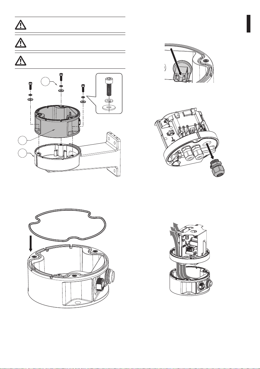
Fasten the support using the 3 holes (01). Use the
screws with a diameter equal to 8mm.
01
Fig. 1
For correct perforation of the fastening surface, use
the perforation masking supplied.
For installation combined with the UEBW support,
fasten the support with quick connectors (02) to the
wall support (03) using the screws and the washer
(04) supplied, paying attention to alignment of the
two supports (Fig. 2, page3).

Instruction manual - English - EN
3MNLKUEBP4_2330_EN
Use the screws and washers provided.
Apply thread-locker into the holes for
screws (Loctite 222®).
Pay attention to the xing. Tightening
torque: 4.5Nm (±0.2Nm).
04
02
03
Fig. 2
Insert the O-ring supplied in the compartment
indicated in the gure (Fig. 3, page3).
Fig. 3
6.2 Cable management
Connect the Ethernet cable supplied to the Ethernet
connector of the support.
Fig. 4
Remove the cable gland.
Fig. 5
Insert the cables in the cable glands of the base of
the PTZ camera.
Pass the Ethernet cable through the hole without
the cable gland.
Fig. 6
The Ethernet cable provided must not be cut.
Once the cables are inserted, it is not necessary to
tighten the cable glands.

EN - English - Instruction manual
4 MNLKUEBP4_2330_EN
6.3 Fixing the base to the support
Use the screws and washers provided.
Apply thread-locker into the holes for
screws (Loctite 222®).
Pay attention to the xing. Tightening
torque: 4.5Nm (±0.2Nm).
Fasten the base (01) on the support (02) using the
screws and washers (03).
03
01 02
Fig. 7
6.4 Connection of the connector
board
The earth ground cable must always be connected
to the relevant terminal (GND).
The remaining 3 or 6 cables can be connected
to the connectors’ board based on installation
requirements.
Refer to the PTZ camera manual for connection and
completion of PTZ camera installation.
6.5 Mobile connectors cabling
(Ethernet)
Use of Ethernet cables with the following
characteristics is highly recommended:
• Cable diameter: from 5mm (0.2in) up to 6mm
(0.24in).
• For the type of cable, refer to the PTZ camera
manual.
Cable the mobile connector by operating as follows.
Insert the Ethernet cable using the sealing nut (01),
the cage (02), the gasket (03) and the body of the
connector (04).
0103
0204
Fig. 8
Crimp connector RJ45.
Carry out the connections as described in the table
(according to the standard specications: TIA/EIA-
568-B) (Tab. 1, page4).
CONNECTION OF THE ETHERNET CABLE
Pin number Cable colour
1Orange-White
2Orange
3Green-White
4Blue
5Blue-White
6Green
7Brown-White
8Brown
Tab. 1

Instruction manual - English - EN
5MNLKUEBP4_2330_EN
Delicately pull the Ethernet cable (05) until the
RJ45 connector (06) is completely inserted in the
compartment of the mobile connector body.
After inserting the cage and the gasket, tighten the
sealing nut (07).
Pay attention to the xing. Tightening
torque (sealing nut 07): from 0.9Nm up to
1Nm.
07
05
06
Fig. 9
Fig. 10 Complete assembly.
Connect the mobile connector on the xed
connector and tighten the ring nut.
6.6 Mobile connectors cabling
(power supply, I/O)
Use of cables with the following characteristics is
highly recommended:
• Cable diameter: from 6mm (0.24in) up to 9mm
(0.35in) (gasket with small hole), or from 9mm
(0.35in) up to 12mm (0.47in) (gasket with large
hole).
• For the type of cable, refer to the PTZ camera
manual.
Cable the mobile connector by operating as follows.
Choose the type of gasket suitable for the cable (Fig.
11, page5).
Fig. 11
Insert the cable using the sealing nut (01), the gasket
(02) and the body of the connector (03).
03 02 01
Fig. 12
6.6.1 4-pole connector
For 4-pole connectors, loosen the screws on the
terminals on the front of the connector, insert the
conductors and fasten them tightening the screws.
Pay attention to the xing. Tightening
torque: from 0.3Nm up to 0.35Nm.
1
2
3
Fig. 13 4-pole connector.
4POLE CONNECTOR
Colour Pin number
Yellow-Green GND
Blue 1
Red 2
White 3
Tab. 2

EN - English - Instruction manual
6 MNLKUEBP4_2330_EN
6.6.2 7-pole connector
For 7-pole connectors, weld the conductors in the
pins.
1
2
3
4
5
6
Fig. 14 7-pole connector.
7POLE CONNECTOR
Colour Pin number
Yellow-Green GND
Black 1
Orange 2
Red 3
Blue 4
White 5
Grey 6
Tab. 3
6.6.3 Completion of the assembly
Screw in the body of the connector (04) to the front
with the contacts (05).
Pay attention to the xing. Tightening
torque: From 0.75Nm up to 1Nm.
05 04
Fig. 15
Fasten the sealing nut (06).
Pay attention to the xing. Tightening
torque: 2.5Nm.
06
Fig. 16
Connect the mobile connector on the xed
connector and tighten the ring nut.
7 Technical data
7.1 Mechanical
Support for Esprit Compact (Pelco) and ULISSE EVO
DUAL (VIDEOTEC) camera
Aluminium pressure casting construction
Dimensions: 129x53x180mm (5x2x7in)
Unit weight: 0.65kg (1.4lb)
7.2 Electrical
Ethernet cable: Shielded twisted cable (STP)
4-pole connector:
Power supply cables section: from 0.75mm² (18AWG)
up to 2.5mm² (13AWG).
Cables signal section: from 0.14mm² (26AWG) up to
1mm² (17AWG)
Multipolar cable sheath diameter: from 6mm up to
12mm
7-pole connector:
Power supply cables section: 0.75mm² (18AWG).
Cables signal section: from 0.14mm² (26AWG) up to
0.75mm² (18AWG)
Multipolar cable sheath diameter: from 6mm up to
12mm

Instruction manual - English - EN
7MNLKUEBP4_2330_EN
8 Technical drawings
The indicated measurements are expressed in millimetres.
193
Ø129
53
Ø9
M5
Ø114
34
Ø114
Fig. 17 UEBP4 - UEBP7.
Pelco, Inc.
625 W. Alluvial Ave., Fresno, California 93711 United States
(800) 289-9100 Tel
(800) 289-9150 Fax
+1 (559) 292-1981 International Tel
+1 (559) 348-1120 International Fax
www.pelco.com
Pelco, the Pelco logo, and other trademarks associated with Pelco products referred to in this publication are trademarks of Pelco,
Inc. or its aliates. ONVIF and the ONVIF logo are trademarks of ONVIF Inc. All other product names and services are the property of their
respective companies. Product specications and availability are subject to change without notice.
© Copyright 2023, Pelco, Inc. All rights reserved.
This manual suits for next models
1
Table of contents
Other Motorola solutions Cables And Connectors manuals
Popular Cables And Connectors manuals by other brands

PCB Piezotronics
PCB Piezotronics IMI SENSORS 009M205/100 Installation and operating manual

PCB Piezotronics
PCB Piezotronics 010G10 Installation and operating manual

Roline
Roline 14.01.3556 user manual

Griven
Griven AL4750 instruction manual

Philips
Philips SWV3513W Specifications

Burndy
Burndy Continental Industries thermOweld CR-5 instructions