List of Figures
Figure 1: SLX 5000 Front View.............................................................................................................. 16
Figure 2: SLX 5000 Top Connection Ports.............................................................................................20
Figure 3: SLX 5000 Bottom Ports...........................................................................................................21
Figure 4: SLX 5000 Bottom Ports...........................................................................................................21
Figure 5: Installing the Back Bracket Assembly..................................................................................... 26
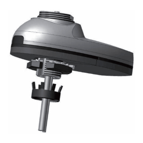
Figure 6: Connecting the GPS Antenna................................................................................................. 27
Figure 7: Installing SLX 5000 on a Pole................................................................................................. 28
Figure 8: SLX 5000 Installed on a Pole.................................................................................................. 29
Figure 9: SLX 5000 Installed on a Wall.................................................................................................. 30
Figure 10: Tilt Adjustment for SLX 5000.................................................................................................31
Figure 11: Ground Connection............................................................................................................... 32
Figure 12: Pre-assembled LC Duplex Cable.......................................................................................... 32
Figure 13: Opening the Housing Lock.................................................................................................... 33
Figure 14: Inserting the Gland Nut on the Cable.................................................................................... 33
Figure 15: Inserting the Tightening Cone on the Cable..........................................................................33
Figure 16: Inserting the Rubber Gland on the Cable..............................................................................33
Figure 17: Passing the Cable through the Housing................................................................................34
Figure 18: Inserting the Cable into the Transceiver................................................................................34
Figure 19: Putting the Holder over the Transceiver................................................................................34
Figure 20: Engaging the Holder in the Housing......................................................................................34
Figure 21: The Holder in the Transceiver............................................................................................... 35
Figure 22: Lifting the Housing Base Lever............................................................................................. 35
Figure 23: Inserting the Rubber Gland................................................................................................... 35
Figure 24: Inserting the Tightening Cone............................................................................................... 35
Figure 25: Tightening the Gland Nut...................................................................................................... 36
Figure 26: Securing the Housing Lock................................................................................................... 36
Figure 27: Pre-assembled RJ45 Cable.................................................................................................. 36
Figure 28: Inserting the Gland Nut on the Cable.................................................................................... 37
Figure 29: Inserting the Tightening Cone on the Cable..........................................................................37
Figure 30: Inserting the Rubber Gland on the Cable..............................................................................37
Figure 31: Inserting the Housing on to the Cable................................................................................... 37
Figure 32: Inserting the Holder on to RJ45.............................................................................................38
Figure 33: Fixing the Holder on the Housing Base.................................................................................38
Figure 34: Aligning RJ45 on the Holder..................................................................................................38
Figure 35: Lifting the Housing Base Lever............................................................................................. 38
Figure 36: Inserting the Rubber Gland................................................................................................... 39
MN007322A01-B
List of Figures
8


