Q1, Q3, and Q15, and to a5-volt regulator (U1), which
provides power to the microcomputer (U3).
All of the timing, monitoring, and sensing of the circuits
is performed by the microcomputer (U3). Upon power-up,
with no battery inserted, the microcomputer performs a
self check of its read-only memory (ROM), random-ac-
cess memory (RAM), and timer. Next, the microcomputer
momentarily turns on all four LEDs via U3, pins 33 thru
36. Then, the microcomputer momentarily turns on each
LED in the sequence: yellow, orange, red, and green.
Completing the self check with no problems encountered,
the microcomputer turns all the LEDs off.
After the microcomputer self check has been com-
pleted, the microcomputer monitors the capacity coding
resistor (RC) RC IN line (U3, pin 23), and the thermistor
(RT) TEMP IN line (U3, pin 24) for battery indications.
When abattery is inserted, the microcomputer again
momentarily turns on each LED in the sequence: yellow,
orange, red, and green.
Next, U3 checks the RC and RT in the battery to deter-
mine charging conditions. If the value of the battery's RC
is abnormal (see Table 1), the microcomputer senses a
problem and, via U3, pin 36, keys the orange LED to flash
on and off. If the RC value is normal, the microcomputer
proceeds to monitor the battery's temperature.
Table 1. Normal RC Values
If the battery temperature is outside the temperature
window (below 10°C (3.33Vdc on the RT contact) or
above 40°C (1.87Vdc on the RT contact), the microcom-
puter lights the yellow Stand-By LED and waits for the
battery's temperature to fall within the temperature win-
dow. Once this occurs, the microcomputer turns off the
yellow LED (if turned on at all) and turns on the charging
circuits; these circuits condition the battery by charging it
at 600mA for 30 seconds. At the end of 30 seconds, the
microcomputer checks the battery voltage via the VCHG
IN line at U3, pin 22. The voltage should be between 7Vdc
and 11Vdc. If the voltage is outside this range, the
microcomputer senses the battery problem and indicates
it by flashing the orange LED (RESEAT/REPLACE THE
BATTERY).
b. Charging Circuits
Following the power-up, microcomputer self check,
battery installation, and normal battery RC, RT, and vol-
tage checks, rapid charging begins. There are four rapid-
charge rates as indicated by the battery RC (see Table 2).
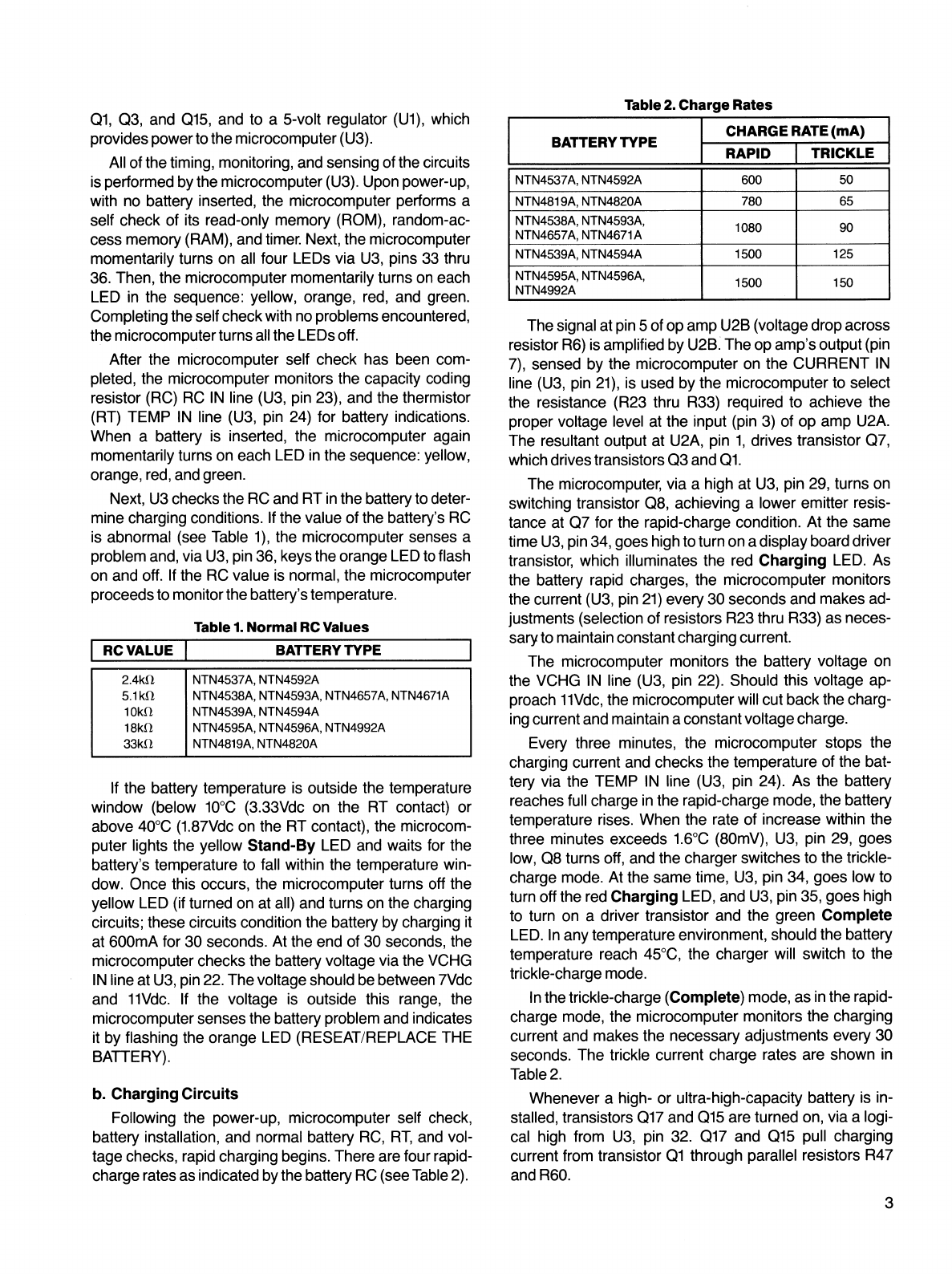
Table 2. Charge Rates
CHARGE RATE (mA)
BATTERY TYPE
RAPID TRICKLE
600 50
NTN4537A, NTN4592A
NTN4819A, NTN4820A 780
NTN4538A, NTN4593A, 1080 90
NTN4657A, NTN4671A
NTN4539A, NTN4594A 1500 125
NTN4595A, NTN4596A, 1500 10
NTN4992A
65
The signal at pin 5of op amp U2B (voltage drop across
resistor R6) is amplified by U2B. The op amp's output (pin
7), sensed by the microcomputer on the CURRENT iN
line (U3, pin 21), is used by the microcomputer to select
the resistance (R23 thru R33) required to achieve the
proper voltage level at the input (pin 3) of op amp U2A.
The resultant output at U2A, pin 1, drives transistor Q7,
which drives transistors Q3 and Q1.
The microcomputer, via ahigh at U3, pin 29, turns on
switching transistor Q8, achieving alower emitter resis-
tance at Q7 for the rapid-charge condition. At the same
time U3, pin 34, goes high to turn on adisplay board driver
transistor, which illuminates the red Charging LED. As
the battery rapid charges, the microcomputer monitors
the current (U3, pin 21) every 30 seconds and makes ad-
justments (selection of resistors R23 thru R33) as neces-
sary to maintain constant charging current.
The microcomputer monitors the battery voltage on
the VCHG IN line (U3, pin 22). Should this voltage ap-
proach 11Vdc, the microcomputer will cut back the charg-
ing current and maintain aconstant voltage charge.
RCVALUE BATTERY TYPE
Every three minutes, the microcomputer stops the
charging current and checks the temperature of the bat-
tery via the TEMP IN line (U3, pin 24). As the battery
reaches full charge in the rapid-charge mode, the battery
temperature rises. When the rate of increase within the
three minutes exceeds 1.6°C (8OmV), U3, pin 29, goes
low, Q8 turns off, and the charger switches to the trickle-
charge mode. At the same time, U3, pin 34, goes low to
turn off the red Charging LED, and U3, pin 35, goes high
to turn on adriver transistor and the green Complete
LED. In any temperature environment, should the battery
temperature reach 45°C, the charger will switch to the
trickle-charge mode.
2.4k0, NTN4537A, NTN4592A
§.1kO NTN4538A, NTN4593A, NTN4657A, NTN4671A
10k. NTN4539A, NTN4594A
18k0, NTN4595A, NTN4596A, NTN4992A
33kN NTN4819A, NTN4820A
In the trickle-charge (Complete) mode, as in the rapid-
charge mode, the microcomputer monitors the charging
current and makes the necessary adjustments every 30
seconds. The trickle current charge rates are shown in
Table 2.
Whenever ahigh- or ultra-high-capacity battery is in-
stalled, transistors Q17 and @15 are turned on, via alogi-
cal high from U3, pin 32. Q17 and Q15 pull charging
current from transistor Q1 through parallel resistors R47
and R60.
3
Q1, Q3, and Q15, and to a5-volt regulator (U1), which
provides power to the microcomputer (U3).
All of the timing, monitoring, and sensing of the circuits
is performed by the microcomputer (U3). Upon power-up,
with no battery inserted, the microcomputer performs a
self check of its read-only memory (ROM), random-ac-
cess memory (RAM), and timer. Next, the microcomputer
momentarily turns on all four LEDs via U3, pins 33 thru
36. Then, the microcomputer momentarily turns on each
LED in the sequence: yellow, orange, red, and green.
Completing the self check with no problems encountered,
the microcomputer turns all the LEDs off.
After the microcomputer self check has been com-
pleted, the microcomputer monitors the capacity coding
resistor (RC) RC IN line (U3, pin 23), and the thermistor
(RT) TEMP IN line (U3, pin 24) for battery indications.
When abattery is inserted, the microcomputer again
momentarily turns on each LED in the sequence: yellow,
orange, red, and green.
Next, U3 checks the RC and RT in the battery to deter-
mine charging conditions. If the value of the battery's RC
is abnormal (see Table 1), the microcomputer senses a
problem and, via U3, pin 36, keys the orange LED to flash
on and off. If the RC value is normal, the microcomputer
proceeds to monitor the battery's temperature.
Table 1. Normal RC Values
If the battery temperature is outside the temperature
window (below 10°C (3.33Vdc on the RT contact) or
above 40°C (1.87Vdc on the RT contact), the microcom-
puter lights the yellow Stand-By LED and waits for the
battery's temperature to fall within the temperature win-
dow. Once this occurs, the microcomputer turns off the
yellow LED (if turned on at all) and turns on the charging
circuits; these circuits condition the battery by charging it
at 600mA for 30 seconds. At the end of 30 seconds, the
microcomputer checks the battery voltage via the VCHG
IN line at U3, pin 22. The voltage should be between 7Vdc
and 11Vdc. If the voltage is outside this range, the
microcomputer senses the battery problem and indicates
it by flashing the orange LED (RESEAT/REPLACE THE
BATTERY).
b. Charging Circuits
Following the power-up, microcomputer self check,
battery installation, and normal battery RC, RT, and vol-
tage checks, rapid charging begins. There are four rapid-
charge rates as indicated by the battery RC (see Table 2).
Table 2. Charge Rates
CHARGE RATE (mA)
BATTERY TYPE
RAPID TRICKLE
600 50
NTN4537A, NTN4592A
NTN4819A, NTN4820A 780
NTN4538A, NTN4593A, 1080 90
NTN4657A, NTN4671A
NTN4539A, NTN4594A 1500 125
NTN4595A, NTN4596A, 1500 10
NTN4992A
65
The signal at pin 5of op amp U2B (voltage drop across
resistor R6) is amplified by U2B. The op amp's output (pin
7), sensed by the microcomputer on the CURRENT iN
line (U3, pin 21), is used by the microcomputer to select
the resistance (R23 thru R33) required to achieve the
proper voltage level at the input (pin 3) of op amp U2A.
The resultant output at U2A, pin 1, drives transistor Q7,
which drives transistors Q3 and Q1.
The microcomputer, via ahigh at U3, pin 29, turns on
switching transistor Q8, achieving alower emitter resis-
tance at Q7 for the rapid-charge condition. At the same
time U3, pin 34, goes high to turn on adisplay board driver
transistor, which illuminates the red Charging LED. As
the battery rapid charges, the microcomputer monitors
the current (U3, pin 21) every 30 seconds and makes ad-
justments (selection of resistors R23 thru R33) as neces-
sary to maintain constant charging current.
The microcomputer monitors the battery voltage on
the VCHG IN line (U3, pin 22). Should this voltage ap-
proach 11Vdc, the microcomputer will cut back the charg-
ing current and maintain aconstant voltage charge.
RCVALUE BATTERY TYPE
Every three minutes, the microcomputer stops the
charging current and checks the temperature of the bat-
tery via the TEMP IN line (U3, pin 24). As the battery
reaches full charge in the rapid-charge mode, the battery
temperature rises. When the rate of increase within the
three minutes exceeds 1.6°C (8OmV), U3, pin 29, goes
low, Q8 turns off, and the charger switches to the trickle-
charge mode. At the same time, U3, pin 34, goes low to
turn off the red Charging LED, and U3, pin 35, goes high
to turn on adriver transistor and the green Complete
LED. In any temperature environment, should the battery
temperature reach 45°C, the charger will switch to the
trickle-charge mode.
2.4k0, NTN4537A, NTN4592A
§.1kO NTN4538A, NTN4593A, NTN4657A, NTN4671A
10k. NTN4539A, NTN4594A
18k0, NTN4595A, NTN4596A, NTN4992A
33kN NTN4819A, NTN4820A
In the trickle-charge (Complete) mode, as in the rapid-
charge mode, the microcomputer monitors the charging
current and makes the necessary adjustments every 30
seconds. The trickle current charge rates are shown in
Table 2.
Whenever ahigh- or ultra-high-capacity battery is in-
stalled, transistors Q17 and @15 are turned on, via alogi-
cal high from U3, pin 32. Q17 and Q15 pull charging
current from transistor Q1 through parallel resistors R47
and R60.
3