manuals.online logo
Brands
  1. Home
  2. •
  3. Brands
  4. •
  5. Motorola
  6. •
  7. Single Board Computer
  8. •
  9. Motorola MVME2600 Series User manual

Motorola MVME2600 Series User manual

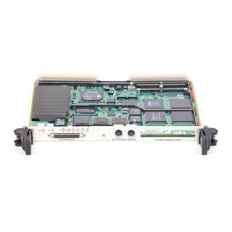
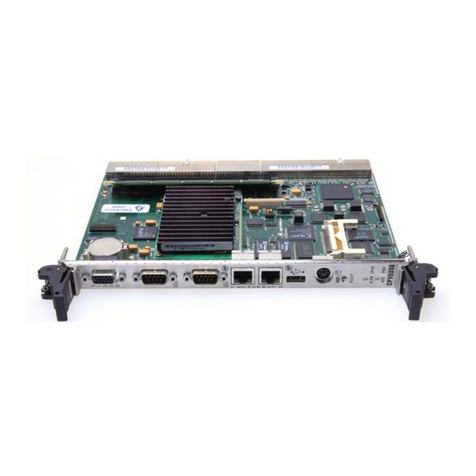
MVME2600 Series
Single Board Computer
Programmer’s
Reference Guide
V2600A/PG1
Notice
While reasonable efforts have been made to assure the accuracy of this document,
Motorola, Inc. assumes no liability resulting from any omissions in this document,
or from the use of the information obtained therein. Motorola reserves the right to
revise this document and to make changes from time to time in the content hereof
without obligation of Motorola to notify any person of such revision or changes.
No part of this material may be reproduced or copied in any tangible medium, or
stored in a retrieval system, or transmitted in any form, or by any means, radio,
electronic, mechanical, photocopying, recording or facsimile, or otherwise,
without the prior written permission of Motorola, Inc.
It is possible that this publication may contain reference to, or information about
Motorola products (machines and programs), programming, or services that are
not announced in your country. Such references or information must not be
construed to mean that Motorola intends to announce such Motorola products,
programming, or services in your country.
Restricted Rights Legend
If the documentation contained herein is supplied, directly or indirectly, to the U.S.
Government, the following notice shall apply unless otherwise agreed to in
writing by Motorola, Inc.
Use, duplication, or disclosure by the Government is subject to restrictions as set
forth in subparagraph (c)(1)(ii) of the Rights in Technical Data and Computer
Software clause at DFARS 252.227-7013.
Motorola, Inc.
Computer Group
2900 South Diablo Way
Tempe, Arizona 85282
Preface
The
MVME2600 Series Single Board Computer ProgrammerÕs Reference Guide
provides
brief board level information, complete memory maps, and detailed ASIC chip
information including register bit descriptions for the MVME2600 series Single
Board Computers (also called MVME2603 and MVME2604 in this manual). The
information contained in this manual applies to the single board computers built
from some of the plug-together components listed in the following table.
This manual is intended for anyone who wants to
program these boards in order to
design OEM systems, supply additional capability to an existing compatible
system, or work in a lab environment for experimental purposes.
A basic knowledge of computers and digital logic is assumed.
To use this manual, you should be familiar with the publications listed in
Appendix
A, Related Documentation
.
The following conventions are used in this document:
bold
is used for user input that you type just as it appears. Bold is also used for
commands, options and arguments to commands, and names of programs,
directories, and files.
italic
is used for names of variables to which you assign values. Italic is also used
for comments in screen displays and examples.
courier
is used for system output (e.g., screen displays, reports), examples, and
system prompts.
<RETURN>
or
<CR>
represents the carriage return or enter key.
CTRL
represents the Control key. Execute control characters by pressing the
CTRL
key and the letter simultaneously, e.g.,
CTRL-d
.
MVME2603-1121 MVME2603-2121 RAM200-042
MVME2603-1131 MVME2603-2131 RAM200-043
MVME2603-1141 MVME2603-2141 RAM200-044
MVME2603-1191 MVME2603-2191 RAM200-049
MVME2604-1021 MVME2604-1121 MVME2604-2021 MVME2604-2121
MVME2604-1031 MVME2604-1131 MVME2604-2031 MVME2604-2131
MVME2604-1041 MVME2604-1141 MVME2604-2041 MVME2604-2141
MVME2604-1091 MVME2604-1191 MVME2604-2091 MVME2604-2191
The computer programs stored in the Read Only Memory of this device contain
material copyrighted by Motorola Inc., Þrst published 1990, and may be used only
under a license such as the License for Computer Programs (Article 14) contained
in Motorola's Terms and Conditions of Sale, Rev. 1/79.
All Motorola PWBs (printed wiring boards) are manufactured by UL-recognized
manufacturers, with a ßammability rating of 94V-0.
!
WARNING
This equipment generates, uses, and can radiate electro-
magnetic energy. It may cause or be susceptible to electro-
magnetic interference (EMI) if not installed and used in a
cabinet with adequate EMI protection.
Motorola
¨
and the Motorola symbol are registered trademarks of Motorola, Inc.
PowerStack
TM
, VMEmodule
TM
, and VMEsystem
TM
are trademarks of Motorola,
Inc.
PowerPC
TM
, PowerPC 603
TM
, and PowerPC 604
TM
are trademarks of IBM Corp,
and are used by Motorola, Inc. under license from IBM Corp.
AIX
TM
is a trademark of IBM Corp.
Timekeeper
TM
and Zeropower
TM
are trademarks of Thompson Components.
All other products mentioned in this document are trademarks or registered
trademarks of their respective holders.
©Copyright Motorola 1996
All Rights Reserved
Printed in the United States of America
November 1996
Safety Summary
Safety Depends OnYou
The following general safety precautions must be observed during all phases of operation, service, and
repair of this equipment. Failure to comply with these precautions or with speciÞc warnings elsewhere in
this manual violates safety standards of design, manufacture, and intended use of the equipment.
Motorola, Inc. assumes no liability for the customer's failure to comply with these requirements.
The safety precautions listed below represent warnings of certain dangers of which Motorola is aware. You,
as the user of the product, should follow these warnings and all other safety precautions necessary for the
safe operation of the equipment in your operating environment.
Ground the Instrument.
To minimize shock hazard, the equipment chassis and enclosure must be connected to an electrical ground.
The equipment is supplied with a three-conductor ac power cable. The power cable must be plugged into
an approved three-contact electrical outlet. The power jack and mating plug of the power cable meet
International Electrotechnical Commission (IEC) safety standards.
Do Not Operate in an Explosive Atmosphere.
Do not operate the equipment in the presence of ßammable gases or fumes. Operation of any electrical
equipment in such an environment constitutes a deÞnite safety hazard.
Keep Away From Live Circuits.
Operating personnel must not remove equipment covers. Only Factory Authorized Service Personnel or
other qualiÞed maintenance personnel may remove equipment covers for internal subassembly or
component replacement or any internal adjustment. Do not replace components with power cable
connected. Under certain conditions, dangerous voltages may exist even with the power cable removed. To
avoid injuries, always disconnect power and discharge circuits before touching them.
Do Not Service or Adjust Alone.
Do not attempt internal service or adjustment unless another person capable of rendering Þrst aid and
resuscitation is present.
Use CautionWhen Exposing or Handling the CRT.
Breakage of the Cathode-Ray Tube (CRT) causes a high-velocity scattering of glass fragments (implosion).
To prevent CRT implosion, avoid rough handling or jarring of the equipment. Handling of the CRT should
be done only by qualiÞed maintenance personnel using approved safety mask and gloves.
Do Not Substitute Parts or Modify Equipment.
Because of the danger of introducing additional hazards, do not install substitute parts or perform any
unauthorized modiÞcation of the equipment. Contact your local Motorola representative for service and
repair to ensure that safety features are maintained.
Dangerous Procedure Warnings.
Warnings, such as the example below, precede potentially dangerous procedures throughout this manual.
Instructions contained in the warnings must be followed. You should also employ all other safety
precautions which you deem necessary for the operation of the equipment in your operating environment.
!
WARNING
Dangerous voltages, capable of causing death, are present in
this equipment. Use extreme caution when handling, testing,
and adjusting.
Contents
Introduction 1-1
Manual Terminology 1-1
Overview 1-3
Feature Summary 1-3
System Block Diagram 1-4
Functional Description 1-6
Overview 1-6
Programming Model 1-7
Memory Maps 1-7
Processor Memory Maps 1-7
PCI Memory Maps 1-13
VMEbus Mapping 1-20
Falcon-Controlled System Registers 1-26
System Configuration Register (SYSCR) 1-27
Memory Configuration Register (MEMCR) 1-29
System External Cache Control Register (SXCCR) 1-30
CPU Control Register 1-32
ISA Local Resource Bus 1-33
W83C553 PIB Registers 1-33
PC87308VUL Super I/O (ISASIO) Strapping 1-33
NVRAM/RTC & Watchdog Timer Registers 1-33
Module ConÞguration and Status Registers 1-34
CPU Configuration Register 1-35
Base Module Feature Register 1-36
Base Module Status Register (BMSR) 1-37
Seven-Segment Display Register 1-38
VME Registers 1-38
LM/SIG Control Register 1-39
LM/SIG Status Register 1-40
Location Monitor Upper Base Address Register 1-41
Location Monitor Lower Base Address Register 1-42
Semaphore Register 1 1-42
Semaphore Register 2 1-43
VME Geographical Address Register (VGAR) 1-43
Z85230 ESCC and Z8536 CIO Registers and Port Pins 1-44
Z8536/Z85230 Registers 1-44
Z8536 CIO Port Pins 1-45
ISA DMA Channels 1-48
Introduction 2-1
Overview 2-1
Requirements 2-2
Features 2-2
Block Diagram 2-4
Functional Description 2-5
MPC Bus Interface 2-5
MPC Arbiter 2-5
MPC Map Decoders 2-7
MPC Write Posting 2-8
MPC Master 2-9
MPC Bus Timer 2-10
PCI Interface 2-11
PCI Map Decoders 2-11
PCI Configuration Space 2-12
PCI Write Posting 2-12
PCI Master 2-13
Generating PCI Memory and I/O Cycles 2-14
Generating PCI ConÞguration Cycles 2-15
Generating PCI Special Cycles 2-16
Generating PCI Interrupt Acknowledge Cycles 2-16
Endian Conversion 2-17
When MPC Devices are Big-Endian 2-17
When MPC Devices are Little Endian 2-18
Cycles Originating From PCI 2-19
Error Handling 2-19
PCI/MPC Contention Handling 2-21
Registers 2-23
MPC Registers 2-23
Vendor ID/Device ID Registers 2-25
Revision ID Register 2-25
General Control-Status/Feature Registers 2-26
MPC Arbiter Control Register 2-29
Prescaler Adjust Register 2-30
MPC Error Enable Register 2-31
MPC Error Status Register 2-34
MPC Error Address Register 2-36
MPC Error Attribute Register - MERAT 2-36
PCI Interrupt Acknowledge Register 2-38
MPC Slave Address (0,1 and 2) Registers 2-39
MPC Slave Address (3) Register 2-40
MPC Slave Offset/Attribute (0,1 and 2) Registers 2-41
MPC Slave Offset/Attribute (3) Registers 2-42
General Purpose Registers 2-43
PCI Registers 2-43
Vendor ID/ Device ID Registers 2-45
PCI Command/ Status Registers 2-45
Revision ID/ Class Code Registers 2-47
I/O Base Register 2-48
Memory Base Register 2-49
PCI Slave Address (0,1,2 and 3) Registers 2-50
PCI Slave Attribute/ Offset (0,1,2 and 3) Registers 2-51
CONFIG_ADDRESS 2-52
PCI I/O CONFIG_ADDRESS Register 2-52
PCI I/O CONFIG_DATA Register 2-54
Raven Interrupt Controller Implementation 2-55
Introduction 2-55
The Raven Interrupt Controller (RavenMPIC) Features 2-55
Architecture 2-55
CSRÕs Readability 2-56
Interrupt Source Priority 2-56
ProcessorÕs Current Task Priority 2-56
Nesting of Interrupt Events 2-56
Spurious Vector Generation 2-57
Interprocessor Interrupts (IPI) 2-57
8259 Compatibility 2-57
Raven-Detected Errors 2-58
Timers 2-58
Interrupt Delivery Modes 2-58
Block Diagram Description 2-60
Program Visible Registers 2-61
Interrupt Pending Register (IPR) 2-61
Interrupt Selector (IS) 2-61
Interrupt Request Register (IRR) 2-62
In-Service Register (ISR) 2-62
Interrupt Router 2-62
MPIC Registers 2-64
RavenMPIC Registers 2-64
Feature Reporting Register 2-69
Global Configuration Register 2-70
Vendor Identification Register 2-71
Processor Init Register 2-71
IPI Vector/Priority Registers 2-72
Spurious Vector Register 2-73
Timer Frequency Register 2-73
Timer Current Count Registers 2-74
Timer Basecount Registers 2-74
Timer Vector/Priority Registers 2-75
Timer Destination Registers 2-76
External Source Vector/Priority Registers 2-77
External Source Destination Registers 2-78
Raven-Detected Errors Vector/Priority Register 2-79
Raven-Detected Errors Destination Register 2-80
Interprocessor Interrupt Dispatch Registers 2-80
Interrupt Task Priority Registers 2-81
Interrupt Acknowledge Registers 2-82
End-of-Interrupt Registers 2-82
Programming Notes 2-83
External Interrupt Service 2-83
Reset State 2-84
Operation 2-85
Interprocessor Interrupts 2-85
Dynamically Changing I/O Interrupt Configuration 2-85
EOI Register 2-86
Interrupt Acknowledge Register 2-86
8259 Mode 2-86
Current Task Priority Level 2-86
Architectural Notes 2-87
Introduction 3-1
Overview 3-1
Bit Ordering Convention 3-1
Features 3-1
Block Diagrams 3-2
Functional Description 3-6
Performance 3-6
Four-beat Reads/Writes 3-6
Single-beat Reads/Writes 3-7
DRAM Speeds 3-7
ROM/Flash Speeds 3-11
PowerPC 60x Bus Interface 3-12
Responding to Address Transfers 3-12
Completing Data Transfers 3-12
Cache Coherency 3-12
Cache Coherency Restrictions 3-13
L2 Cache Support 3-13
ECC 3-13
Cycle Types 3-13
Error Reporting 3-14
Error Logging 3-15
DRAM Tester 3-15
ROM/Flash Interface 3-16
Refresh/Scrub 3-20
Blocks A and/or B Present, Blocks C and D Not Present 3-20
Blocks A and/or B Present, Blocks C and/or D present 3-21
DRAM Arbitration 3-22
Chip Defaults 3-22
External Register Set 3-23
CSR Accesses 3-23
Programming Model 3-24
CSR Architecture 3-24
Register Summary 3-29
Detailed Register Bit Descriptions 3-32
Vendor/Device Register 3-33
Revision ID/ General Control Register 3-33
DRAM Attributes Register 3-35
DRAM Base Register 3-37
CLK Frequency Register 3-37
ECC Control Register 3-38
Error Logger Register 3-41
Error_Address Register 3-43
Scrub/Refresh Register 3-43
Refresh/Scrub Address Register 3-44
ROM A Base/Size Register 3-45
ROM B Base/Size Register 3-48
DRAM Tester Control Registers 3-51
32-Bit Counter 3-51
Test SRAM 3-52
Power-Up Reset Status Register 1 3-53
Power-Up Reset Status Register 2 3-53
External Register Set 3-54
Software Considerations 3-55
Parity Checking on the PowerPC Bus 3-55
Programming ROM/Flash Devices 3-55
Writing to the Control Registers 3-55
Sizing DRAM 3-56
ECC Codes 3-59
Data Paths 3-61
General Information 4-1
Introduction 4-1
Product Overview - Features 4-1
Functional Description 4-2
Architectural Overview 4-2
VMEbus Interface 4-4
PCI Bus Interface 4-5
Interrupter and Interrupt Handler 4-6
DMA Controller 4-7
Registers - Universe Control and Status Registers (UCSR) 4-8
Universe Register Map 4-9
Universe Chip Problems after a PCI Reset 4-14
Problem Description 4-14
Examples 4-16
Example 1: MVME2600 Series Board Exhibits Problem 4-16
Example 2: MVME3600 Series Board Acts Differently 4-17
Example 3: Universe Chip is Checked at Tundra 4-19
Introduction 5-1
PCI Arbitration 5-1
Interrupt Handling 5-2
RavenMPIC 5-3
8259 Interrupts 5-4
ISA DMA Channels 5-7
Exceptions 5-8
Sources of Reset 5-8
Soft Reset 5-9
Universe Chip Problems after a PCI Reset 5-9
Error NotiÞcation and Handling 5-10
Endian Issues 5-11
Processor/Memory Domain 5-14
RavenÕs Involvement 5-14
PCI Domain 5-14
PCI-SCSI 5-14
PCI-Ethernet 5-15
PCI-Graphics 5-15
UniverseÕs Involvement 5-15
VMEbus Domain 5-15
ROM/Flash Initialization 5-16
Motorola Computer Group Documents A-1
ManufacturersÕ Documents A-2
Related SpeciÞcations A-7
Abbreviations, Acronyms, and Terms to Know GL-1
List of Figures
MVME2600 Series System Block Diagram 1-5
VMEbus Master Mapping 1-21
VMEbus Slave Mapping 1-23
Raven Block Diagram 2-4
PCI Spread I/O Cycle Mapping 2-15
Big to Little Endian Data Swap 2-18
RavenMPIC Block Diagram 2-60
Falcon Pair Used with DRAM in a System 3-3
Falcon Internal Data Paths (SimpliÞed) 3-4
Overall DRAM Connections 3-5
Data Path for Reads from the Falcon Internal CSRs 3-24
Data Path for Writes to the Falcon Internal CSRs 3-25
Memory Map for Byte Reads to the CSR 3-26
Memory Map for Byte Writes to the Internal Register Set and Test SRAM 3-27
Memory Map for 4-Byte Reads to the CSR 3-28
Memory Map for 4-Byte Writes to the Internal Register Set and Test SRAM 3-28
PowerPC Data to DRAM Data Correspondence 3-62
Architectural Diagram for the Universe 4-3
UCSR Access Mechanisms 4-8
MVME2600 Series Interrupt Architecture 5-2
PIB Interrupt Handler Block Diagram 5-5
Big-Endian Mode 5-12
Little-Endian Mode 5-13
xv
List ofTables
MVME2600 Series Features Summary 1-3
Default Processor Memory Map 1-8
CHRP Memory Map Example 1-9
Raven MPC Register Values for CHRP Memory Map 1-10
PREP Memory Map Example 1-11
Raven MPC Register Values for PREP Memory Map 1-12
PCI CHRP Memory Map 1-13
Raven PCI Register Values for CHRP Memory Map 1-15
Universe PCI Register Values for CHRP Memory Map 1-15
PCI PREP Memory Map 1-17
Raven PCI Register Values for PREP Memory Map 1-18
Universe PCI Register Values for PREP Memory Map 1-19
Universe PCI Register Values for VMEbus Slave Map Example 1-24
VMEbus Slave Map Example 1-25
System Register Summary 1-26
Strap Pins ConÞguration for the PC87308VUL 1-33
MK48T59/559 Access Registers 1-34
Module ConÞguration and Status Registers 1-35
VME Registers 1-39
Z8536/Z85230 Access Registers 1-44
Z8536 CIO Port Pins Assignment 1-45
Interpretation of MID3-MID0 1-47
PIB DMA Channel Assignments 1-48
CHRP Compliant Memory Map 2-7
MPC Transfer Types 2-10
PCI Command Codes 2-13
Address ModiÞcation for Little Endian Transfers 2-19
Raven MPC Register Map 2-23
Raven PCI ConÞguration Register Map 2-44
Raven PCI I/O Register Map 2-44
RavenMPIC Register Map 2-65
PowerPC 60x Bus to DRAM Access Timing When ConÞgured for
70ns Page Devices 3-8
PowerPC 60x Bus to DRAM Access Timing When ConÞgured for 60ns Page De-
vices. 3-9
xvi
PowerPC 60x Bus to DRAM Access Timing When ConÞgured for 50ns Hyper De-
vices 3-10
PowerPC 60x Bus to ROM/Flash Access Timing When ConÞgured for 32/64-bit
Devices 3-11
PowerPC 60x Bus to ROM/Flash Access Timing When ConÞgured for 8-bit De-
vices 3-11
Error Reporting 3-14
PowerPC 60x to ROM/Flash Address Mapping with Two 8-bit Devices 3-18
PowerPC 60x Address to ROM/Flash Address Mapping with Two 32-bit or One
64-bit Device(s) 3-19
Register Summary 3-30
ram spd1,ram spd0 and DRAM Type 3-34
Block_A/B/C/D ConÞgurations 3-36
rtest encodings 3-44
ROM Block A Size Encoding 3-46
rom_a_rv and rom_b_rv encoding 3-47
Read/Write to ROM/Flash 3-48
ROM Block B Size Encoding 3-50
Sizing Addresses 3-57
PowerPC 60x Address to DRAM Address Mappings 3-58
Syndrome Codes Ordered by Bit in Error 3-59
Single-Bit Errors Ordered by Syndrome Code 3-60
PowerPC Data to DRAM Data Mapping 3-63
Universe Register Map 4-9
PCI Arbitration Assignments 5-1
RavenMPIC Interrupt Assignments 5-3
PIB PCI/ISA Interrupt Assignments 5-6
Reset Sources and Devices Affected 5-9
Error NotiÞcation and Handling 5-10
ROM/FLASH Bank Default 5-16
1
1-1
1Board Description and
Memory Maps
Introduction
This manual provides programming information for the
MVME2603 and MVME2604 Single Board Computers (SBCs), that
are based on the MVME260
x
-
xxxx
base board and the RAM200
mezzanine modules. Extensive programming information is
provided for several Application-Specific Integrated Circuit (ASIC)
devices used on the boards. Reference information is included in
Appendix A for the Large Scale Integration (LSI) devices used on
the boards and sources for additional information are listed.
This chapter briefly describes the board level hardware features of
the MVME2600 series Single Board Computers. The chapter begins
with a board level overview and features list. Memory maps are
next, and are the major feature of this chapter.
Programmable registers in the MVME2600 series that reside in
ASICs are covered in the chapters on those ASICs. Chapter 2 covers
the Raven chip, Chapter 3 covers the Falcon chip set, Chapter 4
covers the Universe chip, and Chapter 5 covers certain
programming features, such as interrupts and exceptions.
Appendix A lists all related documentation.
ManualTerminology
Throughout this manual, a convention is used which precedes data
and address parameters by a character identifying the numeric
format as follows:
For example, Ò12Ó is the decimal number twelve, and Ò$12Ó is the
decimal number eighteen.
$
%
&
dollar
percent
ampersand
speciÞes a hexadecimal character
speciÞes a binary number
speciÞes a decimal number
1-2
Board Description and Memory Maps
1
Unless otherwise specified, all address references are in
hexadecimal.
An asterisk (*) following the signal name for signals which are
level
significant
denotes that the signal is
true
or valid when the signal is
low.
An asterisk (*) following the signal name for signals which are
edge
significant
denotes that the actions initiated by that signal occur on
high to low transition.
Note
In some places in this document, an underscore (_)
following the signal name is used to indicate an active
low signal.
In this manual,
assertion
and
negation
are used to specify forcing a
signal to a particular state. In particular, assertion and assert refer
to a signal that is active or true; negation and negate indicate a
signal that is inactive or false. These terms are used independently
of the voltage level (high or low) that they represent.
Data and address sizes for MPC60
x
chips are defined as follows:
❏
A
byte
is eight bits, numbered 0 through 7, with bit 0 being the
least significant.
❏
A
half-word
is 16 bits, numbered 0 through 15, with bit 0 being
the least significant.
❏
A
word
or
single word
is 32 bits, numbered 0 through 31, with
bit 0 being the least significant.
❏
A
double word
is 64 bits, numbered 0 through 63, with bit 0
being the least significant.
Refer
to Chapter 5 for
Endian Issues
, which covers which parts of the
MVME2600 series use
big-endian
byte ordering, and which use
small-endian
byte ordering.
The terms
control bit
and
status bit
are used extensively in this
document. The term control bit is used to describe a bit in a register
that can be set and cleared under software control. The term
true
is
Overview
1-3
1
used to indicate that a bit is in the state that enables the function it
controls. The term
false
is used to indicate that the bit is in the state
that disables the function it controls. In all tables, the terms 0 and 1
are used to describe the actual value that should be written to the
bit, or the value that it yields when read. The term
status bit
is used
to describe a bit in a register that reflects a specific condition. The
status bit can be read by software to determine operational or
exception conditions.
Overview
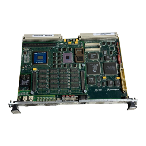
The MVME2600 series SBC family, hereafter sometimes referred to
simply as the MVME2600 or the V2600 series, provides many
standard features required by a computer system: SCSI, Ethernet
interface, keyboard interface, mouse interface, sync and async serial
ports, parallel port, boot Flash, and up to 256MB of ECC DRAM.
Feature Summary
There are many models based on the MVME2600 series
architecture. The following table summarizes the major features of
the MVME2600 series:
Table 1-1. MVME2600 Series Features Summary
Feature Description
Processors Single
Supports BGA processors only: MPC603, MPC604.
Bus Clock Frequencies up to 66MHz
L2 Cache Build-option for 256KB Look-aside L2 Cache
Flash 4MB or 8MB (64-bit wide), with socketed 1MB (16-bit wide)
DRAM 16MB to 256MB, ECC Protected (Single-bit Correction, Double-bit
Detection)
Two-way Interleaved
NVRAM 8KB
1-4
Board Description and Memory Maps
1
System Block Diagram
The MVME2600 series provides the 256KB look-aside external
cache option. The Falcon chip set controls the boot Flash and the
ECC DRAM. The Raven ASIC functions as the 64-bit PCI host
bridge and the MPIC interrupt controller. PCI devices include:
SCSI, VME, Ethernet, and one PMC slot. Standard I/O functions
are provided by the Super I/O device which resides on the ISA bus.
The NVRAM/RTC and the optional synchronous serial ports also
reside on the ISA bus. The general system block diagram for
MVME2600 series is shown below:
RTC MK48T59/559 Device
Peripheral
Support
Two async serial ports
Two sync/async serial ports
One (IEEE1284, or printer) Parallel Port
8-bit or 16-bit single-ended SCSI interface
AUI or 10Base-T/100Base-TX Ethernet interface
NO Graphics Interface on MVME2600 series
One PS/2 Keyboard and one PS/2 Mouse
One PS/2 Floppy Port
VME Interface 32-bit Address/64-bit Data PCI
A32/A24/A16, D64 (MBLT)/D32/D16/D08 Master and Slave
Programmable Interrupter & Interrupt Handler
Full System Controller Functions
Programmable DMA Controller with link list support
Location Monitor
PMC Slots One 32/64-bit Slot
Miscellaneous RESET/ABORT Switch
Status LEDs
Table 1-1. MVME2600 Series Features Summary (Continued)
Feature Description

Other manuals for MVME2600 Series

3

This manual suits for next models

24

Other Motorola Single Board Computer manuals

Motorola MVME177P Quick start guide

Motorola

Motorola MVME177P Quick start guide

Motorola MVME177 Guide

Motorola

Motorola MVME177 Guide

Motorola MVME2400 Series User manual

Motorola

Motorola MVME2400 Series User manual

Motorola CompactPCI CPV5350 Installation and operating manual

Motorola

Motorola CompactPCI CPV5350 Installation and operating manual

Motorola McIAS 1610 Series User guide

Motorola

Motorola McIAS 1610 Series User guide

Motorola M68MPFB1632 User manual

Motorola

Motorola M68MPFB1632 User manual

Motorola CompactPCI CPN5365 Operating manual

Motorola

Motorola CompactPCI CPN5365 Operating manual

Motorola MVME2600 Series Guide

Motorola

Motorola MVME2600 Series Guide

Motorola MVME187 User manual

Motorola

Motorola MVME187 User manual

Motorola MVME167-32 User manual

Motorola

Motorola MVME167-32 User manual

Motorola MVME2100 User manual

Motorola

Motorola MVME2100 User manual

Motorola MVME1603 Quick start guide

Motorola

Motorola MVME1603 Quick start guide

Motorola MVME5100 Series Quick start guide

Motorola

Motorola MVME5100 Series Quick start guide

Motorola MVME297-002 User manual

Motorola

Motorola MVME297-002 User manual

Motorola MCP750HA Series Quick start guide

Motorola

Motorola MCP750HA Series Quick start guide

Motorola MVME6100 User manual

Motorola

Motorola MVME6100 User manual

Motorola MVME197DP User manual

Motorola

Motorola MVME197DP User manual

Motorola CPIP5430 Quick start guide

Motorola

Motorola CPIP5430 Quick start guide

Motorola MVME1603 Quick start guide

Motorola

Motorola MVME1603 Quick start guide

Motorola IXP/CPCI-9120 User manual

Motorola

Motorola IXP/CPCI-9120 User manual

Motorola MVME197LE User manual

Motorola

Motorola MVME197LE User manual

Motorola MCPN750A Quick start guide

Motorola

Motorola MCPN750A Quick start guide

Popular Single Board Computer manuals by other brands

Advantech PCM-9389 Startup manual

Advantech

Advantech PCM-9389 Startup manual

Lex 3I270D manual

Lex

Lex 3I270D manual

Advantech RSB-3730 user manual

Advantech

Advantech RSB-3730 user manual

EMTOP SBC-IMX8MP quick start guide

EMTOP

EMTOP SBC-IMX8MP quick start guide

VMIC VMICPCI-7611 product manual

VMIC

VMIC VMICPCI-7611 product manual

Concurrent Technologies PP 110/01 Series Technical reference manual

Concurrent Technologies

Concurrent Technologies PP 110/01 Series Technical reference manual

EMAC SoM-3354M user manual

EMAC

EMAC SoM-3354M user manual

Portwell WADE-8172 user guide

Portwell

Portwell WADE-8172 user guide

Aaeon EPIC-HD07 manual

Aaeon

Aaeon EPIC-HD07 manual

IBASE Technology IB811F Series user manual

IBASE Technology

IBASE Technology IB811F Series user manual

IEI Technology ICE-BDE-T7 Quick installation guide

IEI Technology

IEI Technology ICE-BDE-T7 Quick installation guide

Arbor Technology EmETXe-a58M0 user manual

Arbor Technology

Arbor Technology EmETXe-a58M0 user manual

SeaLevel SBC-R9-2100 user manual

SeaLevel

SeaLevel SBC-R9-2100 user manual

Acrosser Technology AR-B1663 manual

Acrosser Technology

Acrosser Technology AR-B1663 manual

MicroSys Electronics miriac SBC-LS1088A-TSN user manual

MicroSys Electronics

MicroSys Electronics miriac SBC-LS1088A-TSN user manual

Avnet SMARC MSC SM2S-IMX8M user manual

Avnet

Avnet SMARC MSC SM2S-IMX8M user manual

Vantron VT-M2M-C335L user manual

Vantron

Vantron VT-M2M-C335L user manual

Acrosser Technology AR-B1684VSL2 Operation manual

Acrosser Technology

Acrosser Technology AR-B1684VSL2 Operation manual

manuals.online logo
manuals.online logoBrands
  • About & Mission
  • Contact us
  • Privacy Policy
  • Terms and Conditions

Copyright 2025 Manuals.Online. All Rights Reserved.