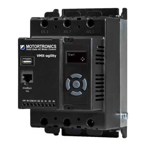
motortronics VMX-Synergy Plus VMX-SGY-I-17 User manual


2
Safety
Caution Statements
The examples and diagrams in this manual are included solely for illustrative purposes. The
information contained in this manual is subject to change at any time and without prior notice.
In no event will responsibility or liability be accepted for direct, indirect or consequential
damages resulting from the use or application of this equipment.
Mises en garde
informations présentées dans ce manuel peuvent être modifiées sans avis préalable.En aucun
Short Circuit
Motortronics soft starts are not short circuit proof. After severe overload or short circuit, the
operation of the soft start should be fully tested by an authorized service agent.
Court-circuit
Les démarreurs progressifs Motortronics -circuits. Après une
forte surcharge ou un court-circuit, le fonctionnement du démarreur progressif doit être
intégralement vérifié par un agent de maintenance agréé.
Important information
Installers should read and understand the instructions in this guide prior to installing, operating
and maintaining the soft start. The following symbols may appear in this guide or on the soft
start to warn of potential hazards or to draw attention to certain information.
Dangerous Voltage
Indicates the presence of a hazardous voltage which could result in personal injury or death.
Tension dangereuse
Warning/Caution
Indicates a potential hazard. Any instructions that follow this symbol should be obeyed to avoid
possible damage to the equipment, and personal injury or death.
Avertissement/Mise en garde
Indique un danger potentiel. Toutes les instructions suivant ce symbole doivent être observées,
Protective Earth (Ground)
Indicates a terminal which is intended for connection to an external conductor for protection
against electric shock in case of a fault.
Mise à la terre (Masse)
protection contre les chocs électriques en cas de défauts.
3
• VMX-Synergy Plus™ soft starts contain dangerous
voltages when connected to the mains supply. Only
qualified personnel that have been completely trained
and authorized, should carry out installation, operation
and maintenance of this equipment.
• Les démarreurs progressifs VMX-Synergy Plus ™
contiennent des tensions dangereuses, lorsqu’ils sont
connectés à la tension secteur. Les activités
d’installation, d’utilisation et d’entretien de cet
équipement doivent être effectuées par un personnel
qualifié, dûment formé et habilité.
• Installation of the soft start must be made in
accordance with existing local and national electrical
codes and regulations and have a minimum protection
rating.
• Le démarreur progressif doit être installer
conformément au code local et nationale d’électricité et
à la réglementation en vigueur, et il doit avoir un indice
de protection minimal
• It is the responsibility of the installer to provide
suitable grounding and branch circuit protection in
accordance with local electrical safety codes.
• Il appartient à l’installeur d’assurer la mise à la terre
et la protection du circuit de branchement,
conformément au code de sécurité électrique local.
• This soft start contains no serviceable or re-usable
parts.
• Ce démarreur progressif ne contient pas de pièces
réparables ou réutilisables
• The STOP function of the soft start does not isolate
dangerous voltages from the output of the soft start.
An approved electrical isolation device must be used
to disconnect the soft start from the incoming supply
before accessing electrical connections.
• La fonction STOP du démarreur progressif n’isole
pas les tension dangereuses en sortie du démarreur
progressif. Avant d’accéder aux raccordement
électriques, il faut utiliser un dispositif d’isolation
électrique approuvé pour déconnecter le démarreur
progressif de la tension d’entrée.
M
3~
1L1 3L2 5L3
2T1 4T2 6T3
Safety

4
Model Number Description
It is essential to check the VMX-Synergy Plus nameplate and make sure that the soft starter is properly
sized for your AC motor.
VMX-SGY-I-17-6-XX-XX
Key Features
Touchscreen
User
Interface
Anybus
Compact
Com Port
Future use
USB Port
Motor
Connections
Status LED
Modbus RTU
Port
Expansion
Port
Supply
Connections
Control Terminals
(Under cover)
Ground
Connection
Keypad
release point
Keypad
release point
Option
Non-critical customer options
(may be blank)
Control supply Us
01 Us= 24Vdc, 110VAC or 230VAC
02 Us= 110VAC
03 Us= 230VAC
Main Supply voltage
6 200VAC to 600VAC, Ui 600V
Model rating designation
VMX-SGY-I-17 to VMX-SGY-I-500

5
Environment - Installation
VMX-SGY-I-17 to VMX-SGY-I-100 (Size 1)
VMX-SGY-I-132 to VMX-SGY-I-195 (Size 2)
Dimensions
Dimensions
VMX-SGY-I-17 to VMX-SGY-I-29
Weight = 3.9 kg (8.6 lbs)
VMX-SGY-I-35 to VMX-SGY-I-100
Weight = 4.2 kg (9.26 lbs)
VMX-SGY-I-132
Weight = 6.7 kg (14.78 lbs)
VMX-SGY-I-160 to VMX-SGY-I-195
Weight = 7.0 kg (15.44 lbs)

6
Environment - Installation
VMX-SGY-I-242 to VMX-SGY-I-361 (Size 3)
VMX-SGY-I-430 to VMX-SGY-I-500 (Size 3)
Dimensions
Dimensions
VMX-SGY-I-242 to VMX-SGY-I-361
Weight = 17.0 kg (37.5 lbs)
VMX-SGY-I-430 to VMX-SGY-I-500
Weight = 22 kg (48.5 lbs)

7
Environment - Installation
Enclosure Internal Clearances
Conductor size and torque requirements
Terminal
Models
Conductor Size
Torque
Metric
Imperial
Nm
Ib-in
Main
Terminals
Cu STR 75oC
only
Terminal
VMX-SGY-I-17 to VMX-SGY-I-100
2.5 - 70mm2
12- 2/0AWG
9
80
VMX-SGY-I-132 to VMX-SGY-I-195
4 - 185mm2
12 –350MCM
14
124
M10 bolt
VMX-SGY-I-242 to VMX-SGY-I-361
2 x 95mm2
2 x 4/0AWG
28
248
VMX-SGY-I-430 to VMX-SGY-I-500
2 x 150mm2
2 x 350MCM
Control terminals
All models
0.2–1.5mm2
24-16AWG
0.5
4.5
Protective
Earth 1)
Cu only
M6 stud
VMX-SGY-I-17 to VMX-SGY-I-41
≥ 6mm2
≥10AWG
8
71
VMX-SGY-I-55 to VMX-SGY-I-80
≥ 10mm2
≥8AWG
VMX-SGY-I-100
≥ 16mm2
≥6AWG
M8 stud
VMX-SGY-I-132 to VMX-SGY-I-160
≥ 16mm2
≥6AWG
12
106
VMX-SGY-I-195
≥ 25mm2
≥4AWG
VMX-SGY-I-242
≥ 35mm2
≥3AWG
VMX-SGY-I-302
≥ 35mm2
≥2AWG
VMX-SGY-I-361
≥ 50mm2
≥1AWG
VMX-SGY-I-430 to VMX-SGY-I-500
≥ 70mm2
≥1/0AWG
1) Protective Earth wire size based on bonding conductor requirements of UL508 Table 7.4 and UL508A Table
15.1, with suitable equivalent metric conductor sizes as per IEC 60947-1 Table 7a.
2) The actual conductor used must comply with local wiring regulations.
Model
A
B
C
mm
inch
mm
inch
mm
inch
VMX-SGY-I-17 to VMX-SGY-I-100
25
0.98
75
2.95
25
0.98
VMX-SGY-I-132 to VMX-SGY-I-195
40
1.57
100
3.93
25
0.98
VMX-SGY-I-242 to VMX-SGY-I-500
60
2.36
125
4.92
25
0,98
A
A
B
B
C
Air Flow

8
Environment - Installation
Enclosure Ventilation
When installing a VMX-Synergy Plusan enclosure, ventilation must be provided if the
heat output of the unit is greater than the cabinet will dissipate. Use the following formula to
determine the fan requirement. An allowance has been incorporated into the formula so that
the figure for Q is the air delivery in the fan data.
Heat dissipated can be approximated with the formulas: -
Starting
Watts (VMX-= start current(A) x start time(s) x number of starts per hour/1200
iERs Disabled
Watts (VMX-(VMX-) x 0.6
iERs Enabled
The maximum power dissipation occurs when energy saving and the iERS is turned on
Watts (VMX-Synergy Plus = (VMX-Synergy Plus current rating) x 1.5
Q = volume of air (cubic metres per hour-m3/h)
Wt = Heat produced by the unit and all other heat sources within the enclosure (Watts)
Tmax = Maximum permissible temperature within the enclosure (50°C for a fully rated VMX-
Synergy Plus
Tamb = Temperature of the air entering the enclosure (°C)
If you prefer to work in CFM, substitute °F for °C. Q is now in CFM
Control Power Consumption
VMX-SGY-I-17 to VMX-SGY-I-361 = 60W
VMX-SGY-I-430 to VMX-SGY-I-500 = 120W

9
Terminal Designations and Wiring Connection

10
Terminal Description
Notes
#1
The programmed digital input setting on D1-COM, D1-1I, D1-2I must correspond to the voltage applied to these
terminals to avoid risk of damage to the equipment.
-COM, D1-1I, D1-2I doit
correspondre à la tension appliquée à ces bornes.
#2
The programmed digital input setting on D2-COM, D2-1I, D2-2I must correspond to the voltage applied to these
terminals to avoid risk of damage to the equipment.
numérique programmé sur D2-COM, D2-1I, D2-2I doit
correspondre à la tension appliquée à ces bornes.
#3
The control supply can be 110 to 230Vac applied to the N, L terminals or 24Vdc applied to the 0Vdc, 24V input
terminals. The correct voltage as specified must only be applied to one of these supply inputs to avoid risk of damage to
the equipment.
mentation.
#4
Refer to VMX-Synergy Plus User Manual for factory default settings.
Model No (s)
US(+10% -15%)
UC(+10% -15%)
Notes
VMX-SGY-I-17-6-01 to
VMX-SGY-I-361-6-01
110-230Vac or 24Vdc
110Vac or 230Vac or
24Vdc
230Vac factory default.
#4
The system can have either a
110/230Vac mains or 24Vdc input NOT
both.
Le système peut avoir soit une
alimentation principale de 110/230Vac ou
de 24 Vdc, mais en aucun cas les deux
imultanement
VMX-SGY-I-430-6-02 to
VMX-SGY-I-500-6-02
110Vac
VMX-SGY-I-430-6-03 to
VMX-SGY-I-500-6-03
230Vac
Table 1: Interface Control Voltages, 2 Amp Supply (continuous)
Terminal
Name
Description
Programmable
Default
Rating
Notes
0V dc
Control Supply
See Table 1, Us
#3
24V dc
Signal ground
AO
Analog Output
0-10V or 4-20mA
ACOM
Analog Common
AI
Analog Input
0-10V or 4-20mA
D2-2I
Digital Input 4 - Group 2
See Table 1, Uc
None
#2
D2-1I
Digital Input 3 - Group 2
See Table 1, Uc
Reset
#2
D2-COM
Digital Input - Group 2 Common
#2
DI-2I
Digital Input 2 - Group 1
See Table 1, Uc
None
#1
DI-1I
Digital Input 1 - Group 1
See Table 1, Uc
Start / Stop
#1
D1-COM
Digital Input - Group 1 Common
#1
N
Control supply
See Table 1, Us
#3
L
12
Digital Output 1 - Group 1 relay N/C
Yes
Fault
230VAC 1A AC15
11 / 23
Digital Output - Group 1 Common
24
Digital Output 2 - Group 1 relay N/O
Yes
Fault
230VAC 1A AC15
34
Digital Output 3 - Group 2 relay N/O
Yes
Running
230VAC 1A AC15
33 / 43
Digital Output - Group 2 Common
44
Digital Output 4 - Group 2 relay N/O
Yes
End of Start
230VAC 1A AC15
54
Digital Output 5 - Group 3 relay N/O
Yes
Running
230VAC 3A AC15
53
Digital Output 5 - Group 3 Common
PTC-
3 x PTC in series (130°C)
PTC+
3 x PTC in series (130 °C)
24Vdc Supply Specification: 24Vdc 60W. Residual ripple 100mV. Spikes/switching peaks 240mV. Turn
On/Off no overshoot of V out. Overvoltage protection output voltage must be clamped to <30Vdc

11
Wiring Connection
M
3~
In Line
M
3~
In Delta
K1 Main contactor or
Circuit breaker isolation
and protection switch gear
(provided by customer)
K1 Main contactor and
and protection switch gear
(provided by customer)
U1 V1 W1
U2 V2 W2
Terml FWD REV
2/T1
4/T2
6/T3
1/L1
3/L2
5/L3
U1 U1
V1 W1
W1 V1
W2 V2
U2 U2
V2 W2
For suitable short
circuit protection devices
Protection in the Technical
Information/ standards
section of this guide.
Pour un dispositif de
protection approprié
contre le court-circuit, voir
la protection contre le
court-circuit dans la
section « Informations
techniques/normes » du
présent guide.
For wire size and
torque requirements see
Technical Information/
standards section of this
guide.
Pour les dimensions de
câble et les besoins en
couple, voir la section «
Informations
techniques/normes » du
présent guide.
In Delta For this configuration applying
the equation.
VMX-Synergy Plus Ie = ie (motor) /
Allows lower current rating VMX-Synergy
Plus than the motor.
The contactor K1 can also be connected
inside the delta circuit.
When connected in the delta
K1 current rating = ie (motor)
En Delta Pour cette configuration,
suivante:
VMX-Synergy Plus Ie = Ie (moteur)/
Cela permet le courant nominal inférieur
de VMX-Synergy Plus par rapport au
moteur.

12
Wiring Connection
3 Wire Control Diagram 3 Wire Control Diagram
110/230Vac control supply (Us) 24Vdc control supply (Us)
and digital input (Uc) programming. and digital input (Uc) programming.
(VMX-SGY-I-17 to VMX-SGY-I-361)
L
N
D1-1I
D1COM
D1-2I
D2COM
D2-1I 53
54
FU1
EMERGENCY STOP
110/230VAC
STOP
START RESET
N
(OPTIONAL)
LINE ISOLATION
CONTACTOR K1
24VDC
0VDC
D1-1I
D1COM
D1-2I
D2COM
D2-1I 53
54
FU1
24VDC
0V
LINE ISOLATION
CONTACTOR
STOP
START RESET
(OPTIONAL)
EMERGENCY STOP
K1
CAUTION
#1
REFER to TABLE 1 on page 11 for input control voltages.
These recommended wiring diagrams are specifically where the control supply voltage (US) is identical to
the control circuit voltage (UC) and not to be supplied separately. Other wiring configurations must also be
in accordance with existing local and national codes and regulations.
RÉFÉRER au TABLEU 1 à la page 12
commande (US) est identique à la tension du circuit de commande (UC). US et UC ne doivent pas être
alimentés séparément. Toutes les configurations de câblage doivent également être en conformité avec les
codes et les règlements locaux et nationaux en vigueur.
#2
Power factor correction capacitors must NOT be positioned between the soft start and the motor or there is
a risk of damaging thyristors due to current peaks.
Condensateurs de correction de facteur de puissance NE doivent pas être placés entre le moteur at le
démarreur progre
110/230Vac (US) and (UC) user programmable 24Vdc (US) and (UC) user programmable
control diagram control diagram (VMX-SGY-I-17 to VMX-SGY-I-361)
L
N
D1-1I
D1COM
D1-2I
D2COM
D2-1I 53
54
FU1
110/230VAC
N
LINE ISOLATION
CONTACTOR
K2
K2
RESET STOP
START
(OPTIONAL)
EMERGENCY STOP
K1 K2
24VDC
0VDC
D1-1I
D1COM
D1-2I
D2COM
D2-1I 53
54
FU1
24VDC
0V
LINE ISOLATION
CONTACTOR
RESET
K2
STOP
START
(OPTIONAL)
EMERGENCY STOP
K1 K2
K2
User programmable inputs are full programmable
method menu found
in the Digital Inputs menu. If you would prefer the reset to work
by removing and reapplying the Start Signal on D1 - 1I then
D1 1I = High Start / Low Stop
D1 2I = None
D2 1I = High Reset

13
Programming
1a
1b
2
3
4
5
6
7
8
9
Screen 1a on 1st Power On only.
Subsequent use will show 1b

14
Rating Table
Minimum current ratings based on typical rated operation currents of motors for the
corresponding rated operational powers
Current rating optimized for kW@600V & hp@550-600V - Ref IEC 60947-4-1 Table G.1 where
applicable.
Size 1,2 and 3
Type
Ie
kW 1)
FLA
Hp 2)
Us
A 3)
230V
400V
500V
A 3)
200V
208V
220-
240V
440-
480V
550-
600V
VMX-SGY-I-17-6-01
17
4
7.5
7.5
17
3
5
5
10
15
VMX-SGY-I-22-6-01
22
5.5
11
11
22
5
5
5
15
20
VMX-SGY-I-29-6-01
29
7.5
15
15
27
7.5
7.5
7.5
20
25
VMX-SGY-I-35-6-01
35
7.5
18.5
22
34
10
10
10
25
30
VMX-SGY-I-41-6-01
41
11
22
22
41
10
10
10
30
40
24VDC,
VMX-SGY-I-55-6-01
55
15
30
37
52
15
15
15
40
50
110VAC
VMX-SGY-I-66-6-01
66
18.5
37
45
65
20
20
20
50
60
to
VMX-SGY-I-80-6-01
80
22
45
55
77
20
25
25
60
75
230VAC
VMX-SGY-I-100-6-01
100
30
55
55
99
30
30
30
75
100
VMX-SGY-I-132-6-01
132
37
75
90
125
40
40
40
100
125
VMX-SGY-I-160-6-01
160
45
90
110
156
50
50
60
125
150
VMX-SGY-I-195-6-01
195
55
110
132
192
60
60
75
150
200
VMX-SGY-I-242-6-01
242
75
132
160
242
75
75
75
200
250
VMX-SGY-I-302-6-01
302
90
160
200
302
100
100
100
250
300
VMX-SGY-I-361-6-01
361
110
200
250
361
125
125
150
300
350
VMX-SGY-I-430-6-02
430
132
250
250
414
150
150
150
350
450
110VAC
VMX-SGY-I-500-6-02
500
150
280
355
480
150
150
150
400
500
VMX-SGY-I-430-6-03
430
132
250
250
414
150
150
150
350
450
230VAC
VMX-SGY-I-500-6-03
500
150
280
355
480
150
150
200
400
500
1) Rated operational powers in kW as per IEC 60072-1 (primary series) corresponding to IEC current rating.
2) Rated operational powers in hp corresponding to FLA current rating according to UL508 and Table 430.250 of the
National Electrical Code.
3) The Ieand FLA rating applies for a maximum surrounding air temperature of 50oC. Above 50oC de-rate linearly by
4% of Ie or FLA per oC to a maximum of 60oC.

15
1
10
100
1000
1 1.5 2 2.5 3 3.5 4 4.5
Trip time ( seconds )
Multiple of Motor FLA
Motor overload 'cold' trip curves (20°C ambient)
Class10 Class20 Class30
Technical Information
Fig 1: Trip curves
Note: When the overload has tripped, there is a forced cooling time to allow the overload to

16
Technical Information & Standards
Rated operational voltages
Ue
200VAC to 600Vac
Rated operational currents
Ie
See Rating Table
Rating index
VMX-SGY-I-17 to VMX-SGY-I-361 Ie: AC-53a:3.5-17:90-5
VMX-SGY-I-430 to VMX-SGY-I-500 Ie: AC-53a:3.5-17:90-3
Rated
frequency/frequencies
50 - 60Hz ± 5Hz
Rated duty
Uninterrupted.
Form designation
Form 1, Internally Bypassed
Rated insulation voltage
Ui
600V
Rated impulse withstand
voltage
Uimp
Main circuit
6kV
Control supply circuit
4kV
IP code
Main circuit
IP00 (IP 20 optional on VMX-
SGY-I-17 to VMX-SGY-I-195)
Supply and Control
circuit
IP20
Overvoltage
Category/Pollution Degree
III/3
Humidity
Max 85% non-condensing, not exceeding 50% at 40°C
Rated conditional short-circuit current and
type of co-ordination with associated short
circuit protective device (SCPD)
Type 1 co-ordination
See Short Circuit Protection Tables for rated
conditional short-circuit current and required current
rating and characteristics of the associated SCPD
Rated control circuit
voltage (programmable)
Uc
24VDC, 110VAC or
230VAC
50 - 60Hz ±5Hz
Protect
with 4A
UL 248
Listed
fuse
Rated control supply
voltage
Us
See Rating Table,
2 Amp supply (cont.)
Relay specification
11, 12, 24 and
33, 34, 44
AC-15, 230VAC, 1A
DC-13 30VDC, 0.7A
53, 54
AC-15, 250VAC, 3A
DC-13 24VDC, 2A
Electronic Overload relay
with manual reset
Trip Class
10, 20 or 30 (See Sizing Guide for associated Ierating)
Current setting
10% Ieto Ie
Rated
frequency
50 to 60Hz ± 5Hz
Time-current
characteristics
See Fig.1 for trip curves (Trip time Tp± 20%)
EMC Emission levels
EN 55011
Class A *
EMC Immunity levels
IEC 61000-4-2
8kV/air discharge or 4kV/contact discharge
IEC 61000-4-3
10 V/m
IEC 61000-4-4
2kV/5kHz (main and power ports)
1kV/5kHz (signal ports)
IEC 61000-4-5
2kV line-to-ground / 1kV line-to-line
IEC 61000-4-6
10V
Transient surge suppression shall be installed on the line side of this equipment and shall be rated 600_V (phase to
phase), suitable for overvoltage category III, and shall provide protection for a rated impulse withstand voltage peak of
or equivalent.
* NOTICE: This product has been designed for environment A. Use of this product in environment
B may cause unwanted electromagnetic disturbances, in which case the user may be required to
take adequate mitigation measures

17
Altitude & Short Circuit Protection
-20°C (-4°F) to 50°C (122°F). Above 50°C (122°F) de-rate linearly by 4 % of VMX-
Synergy Plus Ie per °C to a maximum of 60°C (140°F).
Altitude above sea level 1000m (3281ft). Above 1000m (3281ft) de rate by
1% of VMX-Synergy Plus Ie per 100m (328ft) to a maximum altitude of
2000m (6562ft). Please note for higher temperatures and altitudes contact
your supplier.
Short circuit protection
VMX-Synergy Plus models bearing the UL listing mark are UL 60947-4-2 and CSA C22.2
No.14 listed to US and Canadian safety standards respectively.
Size 1
Type designation (eg. VMX-SGY-I-…)
17
22
29
35
41
55
66
80
100
Rated operational
currents
Ie
A
17
22
29
35
41
55
66
80
100
Rated conditional
short circuit current
Iq
kA
10
10
10
10
10
10
10
10
10
Class J time-delay
fuse #1
Maximum
rating Z1
A
25
30
40
45
60
70
90
100
125
UL Listed inverse-
time delay circuit
breaker #1
Maximum
rating Z2
A
-
-
-
-
-
-
-
-
-
Semiconductor fuse
(class aR) #2
Type
Mersen 6,9 URD 30 _
Bussmann 170M30__
Bussmann 170M31__
Bussmann 170M32__
SIBA 20 61___
Mersen 6,9 URD 31__
Bussmann 170M40__
Bussmann 170M41__
Bussmann 170M42__
SIBA 20 61___
Fuse rating
A
100
100
160
160
200
200
200
315
315
Size 2 and 3
Type designation (eg. VMX-SGY-I-…)
132
160
195
242
302
361
430
500
Rated operational
currents
Ie
A
132
160
195
242
302
361
430
500
Rated conditional
short circuit current
Iq
kA
10
10
10
18
18
18
30
30
Class J time-delay
fuse #1
Maximum
rating Z1
A
175
200
250
350
400
450
600
600
UL Listed inverse-
time delay circuit
breaker #1
Maximum
rating Z2
A
-
-
-
400
500
600
700
800
Semiconductor fuse
(class aR) #2
Type
Mersen 6,9 URD 31__
Bussmann 170M40__
Bussmann 170M41__
Bussmann 170M42__
SIBA 20 61___
Mersen 6,9 URD 33__
Bussmann 170M60__
Bussmann 170M61__
Bussmann 170M62__
SIBA 20 63___
Fuse rating
A
400
550
550
900
900
900
1000
1000
# 1. Suitable for Use On A Circuit Capable Of Delivering Not More Than ___Iq___ rms Symmetrical Amperes, 600
Volts Maximum, When Protected by Class L time delay Fuses with a Maximum Rating of ___Z1___ or by a
Circuit Breaker with a Maximum Rating of ___Z2___.
# 2. Correctly selected semiconductor fuses can provide additional protection against damage to the Synergy Plus
unit (This is sometimes referred to as type 2 co-ordination). These semiconductor fuses are recommended to
provide this increased protection.

18
Sizing Guide
In-Line Connection
Size 1 and 2
Ie
kW
FLA
Hp
Trip Class
10
Trip Class
20
Trip Class
30
A
230V
400V
500V
A
200V
208V
220-240V
440-
480V
550-600V
Ie: AC-53a:
3.5-17: 90-5
VMX-
Ie: AC-53a:
4-19: 90-5
VMX-
Ie: AC-53a:
4-29: 90-5
VMX-
17
4
7.5
7.5
17
3
5
5
10
15
SGY-I-17
SGY-I-22
SGY-I-29
22
5.5
11
11
22
5
5
5
15
20
SGY-I-22
SGY-I-29
SGY-I-35
29
7.5
15
15
27
7.5
7.5
7.5
20
25
SGY-I-29
SGY-I-35
SGY-I-41
35
7.5
18.5
22
34
10
10
10
25
30
SGY-I-35
SGY-I-41
SGY-I-55
41
11
22
22
41
10
10
10
30
40
SGY-I-41
SGY-I-55
SGY-I-66
55
15
30
37
52
15
15
15
40
50
SGY-I-55
SGY-I-66
SGY-I-80
66
18.5
37
45
65
20
20
20
50
60
SGY-I-66
SGY-I-80
SGY-I-100
80
22
45
55
77
20
25
25
60
75
SGY-I-80
SGY-I-100
SGY-I-132
100
30
55
55
99
30
30
30
75
100
SGY-I-100
SGY-I-132
SGY-I-160
132
37
75
90
125
40
40
40
100
125
SGY-I-132
SGY-I-160
SGY-I-195
160
45
90
110
156
50
50
60
125
150
SGY-I-160
SGY-I-195
See Size 3
195
55
110
132
192
60
60
75
150
200
SGY-I-195
See Size 3
See Size 3
Size 3
Ie
kW
FL
A
Hp
Trip Class
10
Trip Class
20
Trip Class
30
A
230V
400V
500V
A
200V
208V
220-
240V
440-
480V
550-600V
Ie: AC-53a:
3.5-17: 90-3
VMX-
Ie: AC-
53a:
4-19: 90-3
VMX-
Ie: AC-53a:
4-29: 90-3
VMX-
160
45
90
110
156
50
50
60
125
150
See Size 2
See Size 2
SGY-I-242
195
55
110
132
192
60
60
75
150
200
See Size 2
SGY-I-242
SGY-I-302
242
75
132
160
242
75
75
75
200
250
SGY-I-242
SGY-I-302
SGY-I-361
302
90
160
200
302
100
100
100
250
300
SGY-I-302
SGY-I-361
SGY-I-430
361
110
200
250
361
125
125
150
300
350
SGY-I-361
SGY-I-430
SGY-I-500
430
132
250
250
414
150
150
150
350
450
SGY-I-430
SGY-I-500
-
500
150
280
355
480
150
150
200
400
500
SGY-I-500
-
-

19
Sizing Guide (Continued)
In-Delta Connection
Size 1 and 2
Ie 1)
kW
FLA
1)
Hp
Trip Class
10
Trip Class 20
Trip Class 30
A
230
V
400
V
500
V
A
200
V
208
V
220-
240V
440-
480V
550-
600V
Ie: AC-53a:
3.5-17: 90-
5
VMX-
Ie: AC-53a:
4-19: 90-5
VMX-
Ie: AC-53a:
4-29: 90-5
VMX-
29
7.5
15
18.5
29
7.5
7.5
10
20
25
SGY-I-17
SGY-I-22
SGY-I-29
38
11
18.5
22
36
10
10
10
25
30
SGY-I-22
SGY-I-29
SGY-I-35
50
11
22
30
47
10
15
15
30
40
SGY-I-29
SGY-I-35
SGY-I-41
61
18.5
30
37
59
15
15
20
40
50
SGY-I-35
SGY-I-41
SGY-I-55
71
18.5
37
45
69
20
20
25
50
60
SGY-I-41
SGY-I-55
SGY-I-66
95
22
45
55
90
25
30
30
60
75
SGY-I-55
SGY-I-66
SGY-I-80
114
30
55
75
113
30
30
40
75
100
SGY-I-66
SGY-I-80
SGY-I-100
139
37
75
90
133
40
40
50
100
125
SGY-I-80
SGY-I-100
SGY-I-132
173
55
90
110
166
50
50
60
125
150
SGY-I-100
SGY-I-132
SGY-I-160
229
55
110
160
215
60
75
75
150
200
SGY-I-132
SGY-I-160
SGY-I-195
277
75
150
185
270
75
75
100
200
250
SGY-I-160
SGY-I-195
See Size 3
338
90
185
220
312
100
100
125
250
300
SGY-I-195
See Size 3
See Size 3
Size 3
Ie 1)
kW
FLA
1)
Hp
Trip Class
10
Trip Class
20
Trip Class
30
A
230V
400V
500V
A
200V
208V
220-
240V
440-
480V
550-
600V
Ie: AC-53a:
3.5-17: 90-3
VMX-
Ie: AC-53a:
4-19: 90-3
VMX-
Ie: AC-53a:
4-29: 90-3
VMX-
277
75
150
185
270
75
75
100
200
250
See Size 2
See Size 2
SGY-I-242
338
90
185
220
312
100
100
125
250
300
See Size 2
SGY-I-242
SGY-I-302
419
132
220
300
419
150
150
150
350
450
SGY-I-242
SGY-I-302
SGY-I-361
523
160
300
375
523
150
150
200
450
500
SGY-I-302
SGY-I-361
SGY-I-430
625
200
355
425
625
200
200
250
500
600
SGY-I-361
SGY-I-430
SGY-I-500
745
220
425
530
717
250
250
250
500
700
SGY-I-430
SGY-I-500
-
866
280
500
630
831
250
300
300
600
800
SGY-I-500
-
-
1) Maximum motor line current indicated. For In-Delta connections, all six motor wires must be available for
connection, and it is critical to exactly follow the In-Delta wiring diagram in the Synergy Plus Quick Start Guide.
The Soft Starter will only sense the Phase Current, which is about 57.7% of the motor line current.
Please refer to the full user manual MAN-VMX-SGY-I-UM for further details

20
Electric current, Danger to life!
Only skilled or instructed persons may carry out the operations.
Livsfara genom elektrisk ström!
Endast utbildade elektriker och personer som undervisats i elektroteknik får
utföra de arbeten som beskrivs nedan.
Lebensgefahr durch Strom!
Nur Elektrofachkräfte und elektrotechnisch unterwiesene Personen dürfen die
im Folgenden beschriebenen Arbeiten ausführen.
Hengenvaarallinen jännite!
Vain pätevät sähköasentajat ja opastusta saaneet henkilöt saavat suorittaa
seuraavat työt.
Tension électrique dangereuse!
Seules les personnes qualifiées et averties doivent exécuter les travaux ci-après.
Nebezpečí úrazu elektrickým proudem!
Níže uvedené práce smějí provádět pouze osoby s elektrotechnickým
vzděláním.
¡Corriente eléctrica! ¡Peligro de muerte!
El trabajo a continuación descrito debe ser realizado por personas cualificadas y
advertidas.
Eluohtlik! Elektrilöögioht!
Järgnevalt kirjeldatud töid tohib teostada ainult elektriala spetsialist vői
elektrotehnilise instrueerimise läbinud personal.
Tensione elettrica: Pericolo di morte!
Solo persone abilitate e qualificate possono eseguire le operazioni di seguito
riportate.
Életveszély az elektromos áram révén!
Csak elektromos szakemberek és elektrotechnikában képzett személyek
végezhetik el a következőkben leírt munkákat.
触电危险!
只允许专业人员和受过专业训练的人员进行下列工作。
Elektriskā strāva apdraud dzīvību!
Tālāk aprakstītos darbus drīkst veikt tikai elektrospeciālisti un darbam ar
elektrotehniskām iekārtām instruētās personas!
Электрический ток! Опасно для жизни!
Только специалисты или проинструктированные лица могут выполнять
следующие операции.
Pavojus gyvybei dėl elektros srovės!
Tik elektrikai ir elektrotechnikos specialistai gali atlikti žemiau aprašytus darbus.
Levensgevaar door elektrische stroom!
Uitsluitelijk deskundigen in elektriciteit en elektrotechnisch geinstrueerde
personen is het toegestaan, de navolgend beschrevene werkzaamheden uit te
voeren.
Porażenie prądem elektrycznym stanowi zagrożenie dla życia!
Opisane poniżej prace mogą przeprowadzać tylko wykwalifikowani elektrycy
oraz osoby odpowiednio poinstruowane w zakresie elektrotechniki.
Livsfare på grund af elektrisk strøm!
Kun uddannede el-installatører og personer der e instruerede i elektrotekniske
arbejdsopgaver, må udføre de nedenfor anførte arbejder.
Življenjska nevarnost zaradi električnega toka!
Spodaj opisana dela smejo izvajati samo elektrostrokovnjaki in elektrotehnično
poučene osebe.
Προσοχή, κίνδυνος ηλεκτροπληξίας!
Οι εργασίες που αναφέρονται στη συνέχεια θα πρέπει να εκτελούνται μόνο
από ηλεκτρολόγους και ηλεκτροτεχνίτες.
Nebezpečenstvo ohrozenia života elektrickým prúdom!
Práce, ktoré sú nižšie opísané, smú vykonávat’ iba elektroodborníci a osoby s
elektrotechnickým vzdelaním.
Perigo de vida devido a corrente eléctrica!
Apenas electricistas e pessoas com formação electrotécnica podem executar os
trabalhos que a seguir se descrevem.
Опасност за живота от електрически ток!
Операциите, описани в следващите раздели, могат да се извършват само
от специалисти-електротехници и инструктиран електротехнически
персонал.
Livsfara genom elektrisk ström!
Endast utbildade elektriker och personer som undervisats i elektroteknik får
utföra de arbeten som beskrivs nedan.
Atenţie! Pericol electric!
Toate lucrările descrise trebuie efectuate numai de personal de specialitate
calificat şi de persoane cu cunoştiinţe profunde în electrotehnică.
Hengenvaarallinen jännite!
Vain pätevät sähköasentajat ja opastusta saaneet henkilöt saavat suorittaa
seuraavat työt.
Življenjska nevarnost zaradi električnega toka!
Spodaj opisana dela smejo izvajati samo elektrostrokovnjaki in elektrotehnično
poučene osebe.
Nebezpečí úrazu elektrickým proudem!
Níže uvedené práce smějí provádět pouze osoby s elektrotechnickým
vzděláním.
Nebezpečenstvo ohrozenia života elektrickým prúdom!
Práce, ktoré sú nižšie opísané, smú vykonávat’ iba elektroodborníci a osoby s
elektrotechnickým vzdelaním.
Опасност за живота от електрически ток!
Операциите, описани в следващите раздели,
могат да се извършват само от
специалисти-електротехници и инструктиран
Eluohtlik! Elektrilöögioht!
Järgnevalt kirjeldatud töid tohib teostada ainult
elektriala spetsialist vői elektrotehnilise
instrueerimise läbinud personal.
Életveszély az elektromos áram révén!
Csak elektromos szakemberek és elektrotechnikában képzett személyek
végezhetik el a következőkben leírt munkákat.
Atenţie! Pericol electric!
Toate lucrările descrise trebuie efectuate numai de personal de specialitate
calificat şi de persoane cu cunoştiinţe profunde în electrotehnică.
Elektriskā strāva apdraud dzīvību!
Tālāk aprakstītos darbus drīkst veikt tikai elektrospeciālisti un darbam ar
elektrotehniskām iekārtām instruētās personas!
Pavojus gyvybei dėl elektros srovės!
Tik elektrikai ir elektrotechnikos specialistai gali atlikti žemiau aprašytus darbus.
Porażenie prądem elektrycznym stanowi zagrożenie dla życia!
Opisane poniżej prace mogą przeprowadzać tylko wykwalifikowani elektrycy
oraz osoby odpowiednio poinstruowane w zakresie elektrotechniki.
California Customers: California Proposition 65 Warning
WARNING: this product and associated accessories may contain chemicals known to the State of California to
cause cancer, birth defects, or other reproductive harm. For more information visit https://p65warnings.ca.gov
MAN-VMX-SGY-I-QS-V03 17/08/2021
This manual suits for next models
7
Table of contents
Other motortronics Controllers manuals

motortronics
motortronics VCM series User manual

motortronics
motortronics VMX-B Soft Start Packages Installation and operating instructions

motortronics
motortronics VMX-18-BP Datasheet

motortronics
motortronics MWH Series Installation and operation manual

motortronics
motortronics XLS Series User manual

motortronics
motortronics VMX Series Operator's manual

motortronics
motortronics Msmart User manual

motortronics
motortronics VCM series User manual

motortronics
motortronics Msmart MVC4 User manual

motortronics
motortronics VMX-synergy series User manual