Motorvac 500-1125B User manual

1324 Blundell Rd. Mississauga ON Tel. 905.615.8620 Fax. 905.615.9745 www.motorvac.com
TRANSTECH IV+
Transmission Service System
Part No. 500-1125B
USER MANUAL

[email protected] www.motorvac.com
Introduction
Congratulations on your selection of the TRANSTECH IV+ Transmission Service System.
By choosing this product, you are acquiring the most technologically advanced method available for auto-
matic transmission service and uid exchange.
The TRANSTECH IV+ System is a self-contained system designed to connect to any automatic transmission
through cooling system lines or vehicle dipstick tube. Once the unit is connected, it can be used to drain the
uid from the vehicle’s transmission for lter replacement and/or to completely exchange the transmission
uid with new uid, without removing the vehicle’s transmission uid pan.
Please study this Operators Manual to become thoroughly familiar with the TRANSTECH IV+ Transmission
Service System.
Thank you for choosing MotorVac.
Sincerely,
The MotorVac Team.

[email protected] www.motorvac.com
Table of Contents
Page
System Features and Functions .………….....………………………….....................................................
Control Panel Features and Functions ………………………………………………............…….…………
Getting to Know the TransTech IV+……………………………………………….….....................…………
Front Features ….………………………………….……………….….....……...............................
Right View ….………………………………….……………….………………................................
Left View ...……………………………………………...................................................................
Safety Information and Precautions …..……………………………………………...……………………......
Auto Prime Procedure …………………………………………………………………..………………….......
First Time Operation ……………………………………………………………………….................
Transmission Service Procedure ……………………………………………………………....……………....
Inline Exchange ……………………………………………………………....……………................
Dipstick Exchange ……………………………………………………………....……………..........
Changing Fluid Types .............................................................................................................................
Maintenance ..........................................................................................................................................
Maintenance Procedures .………………………………………………………..…..……………….
Cleaning the Unit’s Filter Screen ……………………………………………………........…………..
Troubleshooting and Additional Help ……………………………………………………….......…………..…
Error Alerts …………………………………………………………………......................................
System Accessories …………………………………………………………………..…...............................
Parts and Ordering Information …………………………………………………………………..…...............
1
2
3
3
3
3
4-5
6
6
7-11
7-9
10-11
12
13
13
13
14
15
16-18
19

[email protected] www.motorvac.com
System Features and Functions
The front of the TRANSTECH IV+ cabinet contains the control panel, the uid ll neck for adding new trans-
mission uid, and the uid level windows.
Front View - Control Panel Features and Functions
MODE Button - Toggles from Inline to Dipstick and enters manual mode for both functions
INLINE LED - Unit set to Inline exchange when LED is on
(see below, Fig. 1)
DIPSTICK LED - Unit set to Dipstick exchange when LED is on
(see below, Fig. 2)
MANUAL LED – Indicates Manual Mode for either Inline or Dipstick Modes
(see below, Fig. 3 & Fig. 4)
Fig. 1 Fig. 2 Fig. 3 Fig. 4
1
MOTORVAC.COM
LOW
VEHICLE
FLUID
LOW
CLEAN
FLUID
START ENGINE
STOP ENGINE
COMPLETE
SERVICE IN
PROGRESS
STOP
DRAIN
MODE
FILL
EMPTY
WASTE
TransTech lV+
MANUAL
DIPSTICK
INLINE
START /
RESUME
FLUID EXCHANGE

[email protected] www.motorvac.com
Control Panel Features and Functions
2
START/RESUME Button - Begins & Resumes service
DRAIN Button - Drains uid from vehicle’s transmission.
FILL Button – Adds uid to the transmission.
LOW VEHICLE FLUID LED - Illuminates when uid in the vehicle in service is low or
empty.
COMPLETE LED - Illuminates when service is complete.
START ENGINE LED – The LED illuminates when the vehicle’s engine is running in inline
mode. The Start Engine LED ashes when the vehicle’s engine needs to be started.
STOP ENGINE LED – LED illuminates when the vehicle’s engine is OFF in inline mode.
The Stop Engine LED ashes when the vehicle’s engine needs to be stopped.
LOW CLEAN FLUID LED – Illuminates when clean uid in the unit’s clean tank is low or
empty.
STOP BUTTON – Pauses service and stops alarms. Hold for 5 seconds to reset unit.
EMPTY WASTE BUTTON - Empties uid from unit’s waste tank.
MODE BUTTON – Toggles between four different modes (Inline/Dipstick etc)

[email protected] www.motorvac.com
Getting to Know the TransTech IV+
3
Front Features
Control Panel – All electronic operational functions are initiated at this
location. See Control panel features section.
Filler Port & Cap – New ATF is poured into unit before service.
Pressure Gauge – Indicates uid ow through the unit when in Inline mode.
Right Side Features
Dipstick Adapter – Manifold that is permanently attached to DIPSTICK
RETURN hose. The manifold allows the CLEAN FLUID hose to be attached
to it as well as connecting them to a common dipstick wand for the drain
and ll process
Dipstick Hanger – Allows the DIPSTICK RETURN hose and adapter to be
stored safely.
Clean Fluid Hose – Clean ATF is introduced to the vehicle through
this hose. For inline mode connect hose to vehicle, the direction is not
important. Dipstick mode.
Dipstick Return Hose – Draws dirty ATF from the vehicles in Dipstick
Mode.
Left Side Features
Inline Return Hose - Connect to vehicle for inline services. Direction is not
important for inline service
Waste Disposal Hose - Is inserted into the shop’s uid recycling container
or into a suitable container for proper disposal of used transmission uid.
Disposal Hose Ball Valve - Open manually before EMPTY WASTE button
is pushed.

[email protected] www.motorvac.com
Safety Information and Precautions
DANGER:
1. Vehicle exhaust gases contain carbon monoxide, which is a colorless and odorless lethal gas.
2. Only run engines in well-ventilated areas and avoid breathing exhaust gases.
3. Extended breathing of exhaust gases will cause serious injury or death.
WARNING:
1. Exhaust gases, moving parts and hot surfaces are present during and after the engine is running.
2. Read and understand the operator’s manual before using the TRANSTECH IV+ service system.
3. When using petroleum products always refer to the MSDS sheets and manufacturer’s instructions for the
proper procedure to handle emergency medical treatment, cleanup, handling, and storage requirements.
4. Improper use of the TRANSTECH IV+ Transmission Service System or exposure to exhaust gases can
cause injury.
5. Spilled transmission uid on an engine can ignite.
6. Avoid exposure to ames, sparks, hot engine parts and other ignition sources.
7. Always keep a fully charged re extinguisher nearby. The extinguisher should have a class B rating and
be suitable for gasoline, chemical, and electrical res.
8. Cleanup any oil spills immediately.
9. Dispose of contaminated cleanup material according to governing environmental laws.
10. Never look directly into the air induction plenum or carburetor throat when the engine is operating.
11. Always verify hose connections to the transmission’s oil cooler lines before starting the vehicle’s engine.
12. Explosion or ame or exposure to ammable liquid and vapors can cause injury.
13. Flammable liquid (transmission uid) can splash out of reservoir when lling or when unit is being moved.
14. Always keep Reservoir Cap secure except when lling reservoir.
15. Explosion or ame can cause injury.
16. Transmission cooling systems may maintain residual pressure in connection lines to and from transmis-
sion and cooler radiator even after the engine has been turned off.
17. Wear safety goggles.
18. Wear chemical resistant gloves when connecting or disconnecting tting and adapters.
19. Chemicals can cause harmful byproducts - do not add any chemicals to TRANSTECH IV+ reservoir tank.
20. Use only approved automatic transmission uid.
21. Do not swallow or ingest any chemicals.
22. Use with adequate ventilation. Avoid breathing vapors.
23. Do not store chemicals in or on the machine (other than automatic transmission uid).
24. Improper use of transmission uid can cause injury.
25. Over exposure can have harmful effects on eyes, skin, respiratory system and possible unconsciousness
and asphyxiation.
26. Improperly blocked vehicles can move.
27. Set the parking brake and chock the wheels.
28. Moving vehicles can cause injury.
4

Safety Information and Precautions (Cont’d)
Moving engine parts:
1. The engine cooling fan will cycle on and off depending on the coolant temperature and could operate
without the engine running.
2. Wear safety goggles.
3. Always keep objects, clothing, and hands away from the cooling fans and engine parts.
4. Moving engine parts can cause injury.
5. Hot surfaces are present during and after running the engine.
6. Do not contact hot surfaces such as, manifolds, pipes, mufers, catalytic converters, or radiators and
hoses.
Hot surfaces can cause injury:
1. Catalytic converters become extremely hot.
2. Do not park a converter-equipped vehicle over dry grass, leaves, paper, or any other ammable material.
3. Do not touch a catalytic converter until the engine has been off for at least 45 minutes.
4. Catalytic converters can cause burns.
5. Cracked fan blade can become airborne.
6. Examine fan blades for cracks. If found, do not service the vehicle.
7. Flying objects can cause injury.
8. Batteries produce explosive gases and can explode, resulting in injury.
9. Wear safety goggles when working on or near batteries.
10. Use in a well-ventilated area.
11. Keep sparks and ames away from the battery and never lay tools, equipment, or other conductive
objects on the battery.
12. When is connecting to the battery, make sure the unit’s power switch is off. Connect the positive lead of
the unit to the positive lead battery rst; connect the negative lead of the unit to a solid ground point as
far from the battery as possible.
13. Keep battery acid away from skin or eyes. In case of eye contact, ush with clean water for 15 minutes
and get medical attention.
[email protected] www.motorvac.com
5
IMPORTANT
Do not perform the transmission service if the vehicle’s engine oil or coolant level is low. If
necessary, add motor oil and/or coolant.
Do not perform service if new transmission uid is below 50 degrees Fahrenheit.
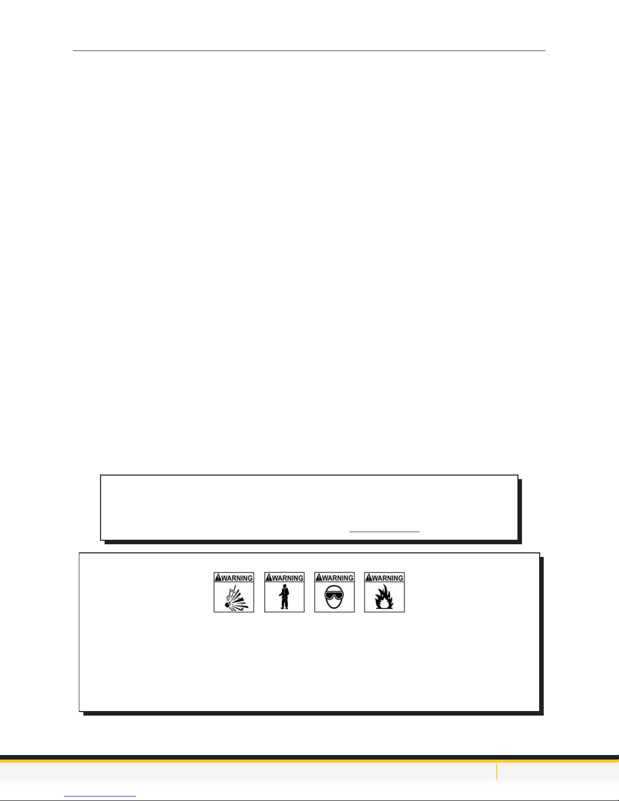
WARNING
Flammable Liquid can squirt out of pressurized lines when connecting or disconnecting.
Verify that engine and machine are both off before connecting or disconnecting cooler
lines or adapters.
Wear safety goggles.
Wear chemical resistant gloves when connecting or disconnecting ttings and adapters.
Wrap a shop towel around pressure ttings and adapters when disconnecting.
Avoid exposure to ames, sparks, hot engine parts, and other ignition sources.
Explosion or ame or exposure to ammable liquid and vapors can cause injury.

[email protected] www.motorvac.com
TransTech IV+ Auto-Prime Procedure
(For rst time set-up only)
Set-Up Instructions:
1. Check the output/return hoses, battery connections, and all external components for damage.
2. Fill the CLEAN FLUID tank with approximately 6 quarts (5.7 liters) of new ATF.
3. Connect two compatible adapters to each other, secure tightly. Attach the CLEAN FLUID & INLINE
RETURN hoses together using the connected adapters
4. Place the waste hose into the clean tank ll neck with the ball valve open.
5. Attach the units’ red (+) battery clip to vehicle’s positive battery terminal; connect the black (-) battery clip
to a solid ground point as far from the battery as possible.
6. Check to ensure the unit is in Inline mode (Inline LED is on). Press and hold the START button for 5
seconds until the unit sounds the alarm. The FILL and DRAIN LEDs will ash. Press and hold the
START button again for 5 seconds until the unit sounds the alarm. The DRAIN, FILL and COMPLETE
LEDs will cycle in a clockwise direction while the unit is performing the Auto-Prime procedure. The unit
will pump uid from the clean tank to the waste tank. The unit will then set the waste tank zero level by
pumping uid from the waste tank into the clean tank. When complete, the unit will automatically reset.
7. Return the hoses to their original location.
8. The initial setup is complete.
6

[email protected] www.motorvac.com
Transmission Service Procedure
Inline Exchange
Warning: It is not necessary to empty the waste tank before beginning an exchange. If beginning an
exchange with uid in the waste tank ensure that there is less uid in the clean tank than the remaining
capacity of the waste tank. Failure to do so will result in waste tank overowing!
Connection to Vehicle
1. Connect appropriate adapters to vehicle transmission cooler lines.
2. Start the vehicle.
3. Observe pressure gauge and toggle ow direction switch between position A and B. Whichever position
has greater pressure is correct. Leave valve in that position for the entire service
7
Select position with
higher pressure

[email protected] www.motorvac.com
Inline Exchange (Cont’d)
Automatic Fluid Exchange Operation.
1. Make sure the TransTech IV+ new uid tank is lled with the correct type and amount of Transmission
Fluid.
2. Connect TransTech IV+ power leads to the vehicle’s battery.
3. Follow steps 1 - 3 in connection to vehicle section. (page 7)
4. Press START/RESUME button to begin the exchange.
5. When uid exchange is nished, the COMPLETE light will come on and TransTech will beep continu-
ously until STOP button is pressed.
6. Once transmission service is complete, check ATF level with engine running or as per manufacturer’s
recommendation. Press and hold DRAIN or FILL to adjust ATF level. Stop the engine, the service is
complete.
7. Direct waste hose to a suitable container; open the ball valve on the end of the waste hose and press
EMPTY WASTE button to empty dirty uid tank.
8
MOTORVAC.COM
LOW
VEHICLE
FLUID
LOW
CLEAN
FLUID
START ENGINE
STOP ENGINE
COMPLETE
SERVICE IN
PROGRESS
STOP
DRAIN
MODE
FILL
EMPTY
WASTE
TransTech lV+
MANUAL
DIPSTICK
INLINE
START /
RESUME
FLUID EXCHANGE
Control Panel Pressure Gauge

[email protected] www.motorvac.com
Optional Procedure - Drain Pan for Filter Change
Warning: It is not necessary to empty the waste tank before beginning an exchange. If beginning an
exchange with uid in the waste tank ensure that there is less uid in the clean tank than the remaining
capacity of the waste tank. Failure to do so will result in waste tank overowing!
1. Make sure the TransTech IV+ new uid tank is lled with the correct type and amount of transmission
uid.
2. Connect TransTech IV+ power leads to the vehicle’s battery.
3. Follow steps 1 - 3 in connection to vehicle section. (page 7)
4. With the TransTech connected and engine running, press DRAIN. When the transmission pan is
emptied, ATF pressure in the machine drops, a buzzer will sound. The LOW VEHICLE FLUID and
STOP ENGINE lights will ash.
5. Immediately turn off the vehicle’s engine and press STOP to silence the alarm. Perform drain pan
service.
6. When the lter change is complete, press START/RESUME button and the TransTech IV+ will rell the
vehicle with the same amount of uid removed.
7. The buzzer will sound and START ENGINE light will ash.
8. Start vehicle.
9. Press START/RESUME button to begin the exchange.
10. When uid exchange is nished, the COMPLETE light will come on and TransTech will beep continuously
until STOP button is pressed.
11. Once transmission service is complete, check ATF level with engine running or as per manufacturer’s
recommendation. Press and hold DRAIN or FILL to adjust ATF level. Stop the engine, the service is
complete.
12. Direct waste hose to a suitable container; open the ball valve on the end of the waste hose and press
EMPTY WASTE button to empty dirty uid tank.
Pause Feature
If service needs to be paused at any time press STOP. To resume, press START/RESUME. The machine
will pause indenitely until the START/RESUME button is pressed. While paused, uid will ow through the
machine in a bypass loop.
Adding ATF to Clean Tank
It is recommended that the desired amount of clean ATF to be exchanged is added to the Clean Tank before
a service begins. However, additional ATF can be added after a service has started but ONLY when the
service is paused. Any ATF added while the unit is performing a service will not be properly measured and
may result in an OVER FILL of the vehicle’s transmission!
9

[email protected] www.motorvac.com
Dipstick Exchange
Warning: It is not necessary to empty the waste tank before beginning an exchange. If beginning an
exchange with uid in the waste tank ensure that there is less uid in the clean tank than the remaining
capacity of the waste tank. Failure to do so will result in waste tank overowing!
1. Fill the TransTech IV+ new uid tank with the correct type and amount of Transmission Fluid.
2. Connect TransTech IV+ power leads to the vehicle’s battery.
3. Ensure ow direction switch is in position A.
4. Press MODE button to select Dipstick operation. Dipstick indicator will be illuminated.
5. Check the transmission uid level. The Transmission uid level can be adjusted at this time using the
DRAIN or FILL buttons. This will ensure the service completes with the correct amount of uid in the
transmission.
6. Measure the vehicle dipstick and set spacer on dipstick ll tube/drain tube on TransTech IV+ to the
correct length. Insert the TransTech IV+ tube into the vehicles dipstick tube.
7. Press START/RESUME button to begin service.
10

[email protected] www.motorvac.com
11
Dipstick Exchange (Cont’d)
8. The DRAIN light is on solid. Initial drain cycle begins.
9. Once uid ow has stopped, service pauses, FILL light ashes. The operator can continue with service
or remove the drain pan if drain pan service is required.
10. Press FILL button to continue service. The unit will rell the same amount of uid that was drained from
the transmission oil pan. After the initial Fill sequence, the unit will pause and the START ENGINE light
will ash.
11. Start the engine.
12. Press the START/RESUME button to continue the service to completion.
13. The COMPLETE light will turn on when the service is complete and alarm will sound. Press STOP button
to silence alarm.
14. Remove the Dipstick ll adaptor and check the level of transmission uid in the vehicle.
15. If the transmission uid level needs adjustment, re-insert the dipstick ll drain tube back into the vehicle
and adjust the uids as necessary by pressing the DRAIN or FILL buttons.
16. Direct waste hose to a suitable container; open the ball valve on the end of the waste hose and press
EMPTY WASTE to empty dirty uid tank.

[email protected] www.motorvac.com
Changing Fluid Types
Follow these steps if it is necessary to completely empty the clean uid tank in order to
change to another type of uid.
1. Install an open adapter in the clean hose coupler. Ensure direction switch is in position A. Install hose into
a capture container.
2. Connect power cord to a 12 volt DC source. Press the MODE button until both the Dipstick and Manual
LED’s are on.
3. Press & hold the FILL button. The pump will operate until the FILL button is released.
4. Tip the unit slightly backwards to let the uid ow toward the back of the tank for complete evacuation.
5. Pressing the STOP button for ve seconds will reset the unit.
Follow these steps if it is necessary to completely empty the dirty uid tank.
1. Connect the power cord to a 12 volt DC source.
2. Direct the waste hose to a suitable disposal container. Open the ball valve on the end of the waste hose.
3. If the EMPTY WASTE LED is on, press the EMPTY WASTE button. The unit will automatically pump out
the dirty uid until the uid level stops at the switch in the bottom of the tank. The EMPTY WASTE LED
will go off.
4. Press and hold the EMPTY WASTE button for 5 seconds to enter MANUAL WASTE mode. Unit will
beep. Release the button. The EMPTY WASTE LED will ash.
5. Press and hold the EMPTY WASTE button. The pump will operate until the EMPTY WASTE button is
released.
6. Tip the unit slightly backwards to let the uid ow toward the back of the tank for complete evacuation.
7. Pressing the STOP button for ve seconds will reset the unit.
12

[email protected] www.motorvac.com
13
Maintenance Procedures
The following maintenance procedures should be performed on a routine basis:
1. Carefully clean the exterior with a soft cloth to keep the cabinet looking new. Check the cabinet for
dents or impact markings, if found, inspect for damaged components.
2. Check all hoses and wires for cuts or frays.
3. Clean the lter screens after every 100 services or
4. 6 months, which ever comes rst. See the next section for procedure.
Cleaning the Unit’s Internal Filters
1. Disconnect power harness from any power source.
Remove the Phillip head screws that join the top cabinet housing to the lower housing. Remove the cap
from the tank and carefully tip the top cabinet forward.
2. Locate the plastic lter housing, found at the top (back) of each tank. There is also a lter inside the unit
on the DIPSTICK RETURN hose. NOTE: Clean one lter at a time. Unscrew the lter cap by rotating
counter-clockwise.
3. Remove the screen from the lter housing. Clean the screen.
4. Assemble in reverse order. NOTE: Use caution not to pinch O-ring on reassembly
5. Enter initials, date, and a check mark in the appropriate boxes of the Maintenance Record at the end of
the chapter.
6. Replace the external lter located in the INLINE RETURN hose.

[email protected] www.motorvac.com
Troubleshooting and Additional Help
Refer to the list below troubleshooting assistance.
Problem Possible Cause
1. Unit does not power-up. No LED’s are
illuminated
Polarity is reversed on vehicle battery connection.
Check connection to battery for a loose condition.
Circuit breaker may be tripped. (Automatic reset).
Faulty battery
2. Start light does not stop blinking when the
engine is started.
Observe pressure gauge to see if uid/pressure is
reaching the machine.
CLEAN FLUID and Inlet hose may be reversed.
Vehicle may have to be placed in neutral to achieve
pressure. Vehicle may be of a low pressure design
or have a thermostat
3. Fluid is not going into the Waste tank during
inline service.
If the DRAIN LED is on (indicating unit should be
draining), and there is pressure reading on the
gauge, but no uid is going into the waste tank
then the solenoid valve is not ‘switched’. Solenoid
requires a good 12 volts. Low battery voltage,
defective power cable or poor wiring connector
between the board and solenoid can cause this
problem.
4. The unit performs poorly. Verify that the tank lter screen has recently been
cleaned. (Refer to the maintenance log in to view
dates of services performed.)
5. When rst connected to a battery, all the unit’s
lights remain on and gives a steady tone.
Verify good battery voltage (12.5 volts) and
connection.
Unit will not operate off a booster pack. Connect to
a new fully charged battery and try again.
Check wiring for damage
6. Unit will not start. Light (LED) on below the ‘ll
switch’
Check for residual pressure on the gauge. Pressure
in the dirty hose or defective pressure switch or
wiring.
14

MOTORVAC.COM
LOW
VEHICLE
FLUID
LOW
CLEAN
FLUID
START ENGINE
STOP ENGINE
COMPLETE
SERVICE IN
PROGRESS
STOP
DRAIN
MODE
FILL
EMPTY
WASTE
TransTech lV+
MANUAL
DIPSTICK
INLINE
START /
RESUME
FLUID EXCHANGE
Error Alerts
The TransTech IV+ has been designed to stop the service and alert the operator in certain instances if the
unit is not functioning properly. There are 2 different notications, one that occurs while draining and the
other while the unit is lling. See below for details.
Fig.1
[email protected] www.motorvac.com
Alert Notication Cause Hardware
Troubleshooting
steps
Recovery
Fill
Error
see
Fig. 1
The alarm sounds.
The following LEDs
ash: INLINE,
DIPSTICK, MANUAL
FILL.
There is a hardware or
software problem that
has caused the unit
to lose track of how
much uid is in the
Clean Tank.
This alert prevents the
unit from overlling the
transmission if there
is a problem with the
uid level sensing
system.
Flow direction switch
is in position B for
dipstick service
Empty the Clean ATF
tank on the TransTech
IV+ before attempting
another exchange.
Note: Do not leave oil
standing above the 0
line of the clean tank
for extended periods
of time. This may
cause the unit to lose
track of uid levels.
Ensure ow direction
switch is in position
A for dipsticks
service.
Press STOP button to
silence the buzzer.
Due to the probability
of an overll condition,
the unit cannot recover
from this error.
Reset the unit to
attempt further
operation.
15

TransTech System Accessories
[email protected] www.motorvac.com
16
Part Number Mating Part Description Picture ID Mark Vehicles
In Euro Kit
200-3120
Standard
Adapter Kit
200-3100A
Deluxe
Adapter Kit
200-3101A
060-0450 Hose Clamp 7/8” I.D. max General Application
1
060-1000 060-1300 1/4” Male Bump Tube Most Asian Vehicles
1 1
060-1100 060-1400 5/16” Male Bump Tube Most Asian Vehicles
1 1
060-1200 060-1500 3/8” Male Bump Tube Most Asian Vehicles
1 1
060-1300 060-1000 1/4” Open End Hose Most Asian Vehicles
1 1
060-1400 060-1100 5/16” Open End Hose Most Asian Vehicles
1 1
060-1500 060-1200 3/8” Open End Hose Most Asian Vehicles
1 1
060-1700 062-0170 5/16” Flare, 7/16”-24 - Domestic Vehicles
1
060-1800 062-0180 3/8” Flare, 5/8”-20 - Domestic Vehicles
1
060-2000 060-2005 GM 7/16" Inverted Flare Male GM
060-2005 060-2000 GM 7/16" Inverted Flare Female GM
060-2010 060-2015 GM 1/2" Inverted Flare Male GM
060-2015 060-2010 GM 1/2" Inverted Flare Female GM
060-2020 GM 1/2" Hose GM
060-2025 VW M12 VW
060-2030 VW M12 with o-ring VW
2
060-2035 060-2040 Jeep 5/8-18 male Jeep
060-2040 060-2035 Jeep 5/8-18 female Jeep
060-2045 060-2050 SAE J512 45 deg flare 5/8 male
060-2050 060-2045 SAE J512 45 deg flare 5/8 female
060-2055 060-2060 Ford SAE J512 45 deg flare female Ford
060-2060 060-2055 Ford SAE J512 45 deg flare male Ford
060-2065
061-1550 (open
end hose)
ADAPTER TRANS BMW 14 MM MALE BMW
1
060-2070 060-2075 Adapter Trans BMW - M18 x 1.5 M 70 BMW
1
060-2075 060-2070 Adapter Trans BMW - M18 x 1.5 F 75 BMW
1
060-2080
Adapter Trans Saab, Citroen,
Lancia - M14 x 1.5M
80
Saab
Citroen
Lancia
1
060-2090 Adapter Trans Fiat - M12 x 1.75 M 90 Fiat
1
060-2095 060-2105
Adapter Trans Audi - M22 x 1.5 M 95 Audi
1

TransTech System Accessories
[email protected] www.motorvac.com
17
Part Number Mating Part Description Picture ID Mark Vehicles
In Euro Kit
200-3120
Standard
Adapter Kit
200-3100A
Deluxe
Adapter Kit
200-3101A
060-2105 060-2095
Adapter Trans Audi - M22 x 1.5 F 105 Audi
1
060-2110 NA
Adapter Trans Opel Corsa 110 Opel Corsa
1
060-2300
14 mm Female
1
060-2402 060-2740 14mm x 1.5 Banjo Euro / Asia Vehicles
2 1
060-2501 Bypass adapter hose General application
060-2600
060-2300
060-2700
16mm x 1.5 Bubble Flare European Vehicles
1 1
060-2700 Union - M 14mm X 16mm European Vehicles
1
060-2740 060-2402 14mm x 1.5 Banjo Bolt Euro / Asia Vehicles Use with 060-2402
1 1
060-2741 060-2740 14mm Washer Euro / Asia Vehicles
2 1
060-2742 060-2740 14mm x 1.5 Cap Nut Euro / Asia Vehicles
1 1
060-3800
061-0605
061-0005
(optional)
#5 SAE Flare - European Vehicles
1
060-4200 060-1400 5/16” Male Tube with Locking Quick Connect Dodge / Ford Vehicles
1 1
060-4300 060-1500 3/8” Male Tube with Locking Quick Connect Dodge / Ford Vehicles
1 1
061-0008
DODGE DIESEL
ALLISON 540
DODGE DIESEL
ALLISON 540
061-0010
DODGE DIESEL
ALLISON 634
DODGE DIESEL
ALLISON 634
061-0605
062-0140
060-3800
#5 SAE x #6 SAE Union - European Vehicles
1
061-1008
FLARE COUPLER
# 10 x # 8 ALLISON TRANSMISSIONS
061-1550 062-2040 1/2” Open End Hose
Chrysler V-10 Diesel Use
Volvo XC60 & 70
1 1
062-0100
062-2060
062-0110 (old)
5/16” Male Flare-Deep - Ford Vehicles
1
062-0120
062-1034
062-0130 (old)
3/8” Male Flare-Deep Ford Vehicles
1
062-0140 061-0605 #6 SAE Flare - European Vehicles
062-0170 060-1700 5/16” Female Flare - x 1/4” MPT General Application
1
062-0180 060-1800 3/8” Female Flare - x 1/4” MPT General Application
1
062-1034
062-01200
62-0130 (old)
3/8”Female Flare-Deep - Ford Vehicles
1
062-2000 062-2005
BMW (Jaguar & Mercedes)
12 mm Male O-Ring Type / Flange Style
O’Ring P/N: 080-3602
BMW (Jaguar & Mercedes)
1
062-2005 062-2000
BMW (Jaguar & Mercedes)
12mm Female Receptacle / Flange Type
BMW (Jaguar & Mercedes)
1
062-2010 062-2015
10mm Male O’Ring Type / Flange Style
O-Ring P/N: 080-3402
BMW (Jaguar & Mercedes)
1
This manual suits for next models
1
Table of contents
Other Motorvac Other manuals