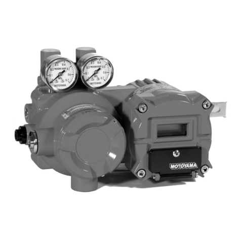
MOTOYAMA EA91A User manual

INSTRUCTIONMANUAL
BulletinNo.MIE-B6104KBulletinNo.MIE-B6104K
ModelEA91A&EA90A
PrintedinJapan
2013.07.05TKP
ModelsEA91AFlameproofTypeof
Explosion-protectedConstruction
ModelEA90AIntrinsicSafetyTypeof
Explosion-protectedConstruction
ELECTRO-PNEUMATIC
VALVEPOSITIONERS
ThisINSTRUCTIONMANUALissuppliedforinformationpurposeonlyandshould
notbeconsideredcertifiedmarketabilityandconformabilityofthisproduct.
□MOTOYAMAiscontinuouslyimprovingandupqradingitsproductdesign,specificationsand/or
dimensions,Informationincludedhereinissubjecttochangewithoutnotice.
■HeadOfficeandFactory
5-2,OhiraAzakameoka,Ohira-Mura,Kurokawa-gun,Miyagi-ken,981-3697Japan
TEL:+81-22-344-4511/FAX:+81-22-344-4533
■OverseasMarketing&SalesDept
5-2,OhiraAzakameoka,Ohira-Mura,Kurokawa-gun,Miyagi-ken,981-3697Japan
TEL:+81-22-344-4546/FAX:+81-22-208-5020

ModelEA91A&EA90A
FOREWORD
29
ThankyouverymuchforpurchasingourModelEA91A/EA90AElectro-pneumatic
ValvePositioner.Takefullynoticethattheitemsdescribedbelowtousethisvalve
positionersafelyandcorrectly.
⑴ ThisInstructionManualdescribesthebasicrecommendedproceduresforopera
-tingtheModelEA91A/EA90AElectro-pneumaticValvePositioner.Thoroughlyread
andunderstandalldescriptionsinthismanualbeforeoperation.ThisInstruction
Manualshouldalwaysbereferredpriortoanyoperations.
⑵ Thisproductismountedtoacontrolvalveasdedicatedequipment.Readand
followallindividualproceduresinthisinstructionmanualwiththeinstructionmanual
ofcontrolvalvewhenworkingandoperatingthisproductmountedtothecontrol
valve.
⑶ As the result of studying and improving this product without notice, the
specifications,dimensions,adjustments,illustrations,andotheritemsincludedin
this manual might be different in details. For any questions about the delivered
product or this instruction manual, contact MOTOYAMA sales office or sales
agencyforpurchasebeforeoperation.
Tohandlethisproductsafely,thesymbolmarksandsignalwordsshownbelow
areusedinthisinstructionmanualtoalertriskasrequired.Thecontentsofsymbol
markandsignalwordaredescribedbelow.
Thismarkwiththissignalisusedwhenthepossibilityof
deathorseriousinjurytouserisassumedifhandlingthis
productincorrectly.
Thismarkandsignalareusedtocomplytheinstructions
topreventdamageofthisproductormalfunction.
Thismarkwiththissignalisusedwhenthepossibilityof
lightinjuryormiddleinjurytouser,orpropertydamage
isassumedifhandlingthisproductincorrectly.
1GeneralInformation
2
SafetyInformation
SymbolMark&
SignalWord Description
WARNING
CAUTION
IMPORTANT

1
ModelEA91A&EA90A
CONTENTS
1.SAFETYINSTRUCTIONS
1.1GeneralSafetyInstructions
1.2
SafetyInstructionsonModelEA91AElectro
-pneumaticValvePositioner
1.3
SafetyInstructionsonModelEA90AElectro
-pneumaticValvePositioner
2.GENERALINFORMATION
2.1Purpose
2.2ApplicableRegulation
2.3Specifications
2.4ModelNumberingSystem
2.5NameplateIdentification
2.6SystemConfiguration
2.7Construction
3.PRINCIPLEOFOPERATION
4.INSTALLATION
4.1MajorDimensions
4.2InstallationConditions
4.3Pre-InstallationCheck
4.4
InstallationtoLinearMotionActuator
4.5
InstallationtoRotaryMotionActuator
4.6ConformityofCapacity
andCharacteristics
4.7InstallingDimensions
………………2
…………2
…………2
…………3
………………4
……………………………………4
…………………4
……………………………4
……………5
………………5
…………………5
………………………………6
……………7
……………………………8
………………………8
…………………9
…………………9
……10
…11
……………………12
…………………14
……………15
…………15
………………………16
………………………16
……………………………19
………………19
…………………20
…20
……………20
…20
………………20
…22
…22
…………………………23
…………………23
………………24
…………………25
…………26
………………26
……………………27
5.EXTERNALCONNECTION
5.1PipingandWiringSystems
5.2PneumaticPiping
5.3ElectricalWiring
6.ADJUSTMENT
6.1Pre-adjustmentCheck
6.2AdjustingProcedure
6.3ZeroAdjustment
(LinearType,CamType:Common)
6.4ZeroAdjustmentforCam
6.5StrokeAdjustment
(LinearType,CamType:Common)
6.6SplitRangeAdjustment
6.7ReversePositionerAdjustment
(LinearType,CamType:Common)
6.8
ManualSwitchingMechanism-A/MSwitching
(LinearType,CamType:Common)
7.MAINTENANCE
7.1PeriodicMaintenance
7.2MaintenanceProcedure
8.TROUBLESHOOTING
9.REFERENCEINFORMATION
9.1PredictedServiceLife
9.2DimensionofFitting
Page Page

CAUTION
CAUTION
CAUTION
CAUTION
WARNING
WARNING
WARNING
2
ModelEA91A&EA90A
SAFETYINSTRUCTIONS
1
ⅡCT6
ⅡCT5
EA91A
EA90A
1.1.1
CompliancewithSafetyInstructions
Whenhandlingandoperatingtheelectro-pneumaticvalvepositioner,allthesafetyinstructionshereinshould
besecurelyfollowed.
1.1.2
ConformancewithSpecifications
BoththeModelEA91AElectro-pneumaticValvePositioner(flameproofexplosion-protectedconstruction)and
theModelEA90AElectro-pneumaticValvePositioner(intrinsicallysafeexplosion-protectedconstruction)
havebeenapprovedinaccordancewiththeLaborSafetyandHygieneLawof"TechnicalCriteriaofElectrical
-mechanicalEquipmentExplosion-protectedConstruction"(hereafterreferredtoas"TechnicalCriteria").
Thecertified seal,andthenameplateorthecautionarylabeldescribingthespecificationstoberequired
protectingexplosionareattachedtoeachvalvepositionerinconformancewithallspecifiedrequirements.
Checktheitemsdescribedinthecertifiedseal,andthenameplateorthecautionarylabel,andusethis
product.
1.1
GeneralSafetyInstructions
1.2.1
LimitationofInstallationLocations
TheEA91AValvePositionercanbeinstalledinthehazardousareaaccordingtotheavailableexplosivegas
ofthevalvepositioner.
However,donotinstalltheEA91AValvePositionerintheClass0hazardousarea.
1.2.2
MaintenanceduringOperation
DonotperformmaintenanceoftheEA91AvalvepositionerwhilethepowerisbeingturnedON.When
performing maintenanceby opening the terminal box with the valvepositioner turned ONdue to
circumstances,carefullymakesurebeforeandduringmaintenancethattheexplosivegasesareabsentusing
gasdetector.
Whenimpossibletocheckwhethertheexplosivegasesareabsentornot,maintenancemustbelimitedto
visualinspectionandadjustmentofmovablepartsnotrequiringtheopeningoftheterminalboxsuchas
zeroadjustmentandstrokeadjustment.Becarefulnottogenerateimpactsparksduringthismaintenance.
1.2.3Repairs
a)TurnOFFthepowerandmovetheEA91AValvePositionertosafetyplacebeforerepairing.
b)Bothmechanicalandelectricrepairsare.limitedtorestoringthevalvepositionertoitsoriginalcondition
inprinciple.
c)Theuseislimitedtotherepairabledegreeonlyusinggeneraltoolswithoutsolderingiron.
1.2.4
ProtectionagainstConventionalShort-circuitCurrent
ThecoilpartfilledwithresinoftheEA91AValvePositioneristhespecialexplosion-protectedconstruction
compliancewiththeTechnicalCriteria.ThisTechnicalCriteriarequiresthe"protectionagainst4000A
conventionalshort-circuitcurrentfortheelectricaldeviceorpartwithresin-filledconstructiontobe
connectedtotheexternalpowersupply".ForthehostdevicesuchascontrollertobeconnectedtotheEA91A
ValvePositioner,usefuseorbreakerwithbreakingcapacity4000Aormore.
"WARNING"sealisaffixedonterminalbox.
1.2SafetyInstructionsonModelEA91AElectro-pneumaticValvePositioner
Applicable
ExplosiveGases
InstallationLocation
Explosion-protectionType
ModelNo.
IntrinsicSafetyType
TechnicalCriteria,ExiaⅡCT6
FlameproofType
TechnicalCriteria,ExsdⅡCT6X
AllgasesclassifiedinGroupleftandDiv.1and2Hazard
-ous Area.Non-Hazardous Area. (Locations specifiedin
TechnicalCriteriaandDivision1and2HazardousArea)
AllgasesclassifiedinGroupleftandDiv.0,1and2Hazard
-ousArea.AllNon-HazardousArea.(Locationsspecifiedin
TechnicalCriteriaandDivision0,1,and2HazardousArea)
1.1.3
ProhibitionofChangingSpecificationsandModifications
Donotchangethespecificationsormodifythevalvepositionersbyuser.

ModelEA91A&EA90A
3
WARNING
WARNING
WARNING
1.3.1
LimitationofInstallationLocation
Theelectricaldevicewiththeintrinsicallysafeexplosion-protectedconstructionconsistsofthecombination
oftheintrinsicsafetydevice(EA90AElectro-pneumaticValvePositioner)tobeinstalledinhazardousarea
andthesafetybarrier(intrinsicsafetyrelateddevice)tobeinstalledinnon-hazardousarea.
TheEA90AValvePositionercanbeinstalledinhazardousareaaccordingtotheavailableexplosivegasof
theintrinsic safetydevice.However, donotinstallthesafetybarriertobeelectricallyconnected tothe
EA90A Valve Positioner inhazardous areaunless the safetybarrier isused incombinationwith other
explosion-protectedconstruction(flameproofexplosion-protectedconstruction,etc.)
1.3.2
CombinationwithSafetyBarrier
ThesafetybarrierthatdoesnotindividuallypassthemodeltestincompliancewiththeTechnicalCriteria
shouldnotbeusedbyconnectingtothiselectric-pneumaticvalvepositionerEA90A.
Theexplosion-protecteddevicetypeofthesafetybarriershallbe"ⅡC "andtheclassificationshallbe"ia".
Besuretocomplywiththeconditionssincetherearelimitationsofinductanceandcapacitanceforsafety
rateandexternalwiring.(RefertoItem2.6.2"ModelEA90AElectro-pneumaticValvePositioner(IntrinsicSafety
Type)"inthismanualformaintenanceoftheEA90AElectro-pneumaticValvePositioner.)
1.3.3Maintenance
ConsultwithMotoyamaformaintenanceoftheEA90AElectro-pneumaticValvePositionerinprinciple.
Ifperformingmaintenancebyuser,readthefollowinginstructionshereinandcarefullyfollowtheinstructions
describedinChapter8"MAINTENANCE"forspecificprocedures.
(1)
MaintenanceofEA90AValvePositioner
WhenperformingmaintenancetheEA90AValvePositionerinstalledinhazardousarea,carefullymakesure
beforeandduringmaintenancewhethertheexplosivegasesareabsentornotbyusinggasdetector.
(2)MaintenanceduringOperation
DonotperformmaintenanceoftheEA90AValvePositionerwhilethepowerisbeingturnedON.
WhenperformingmaintenancewiththevalvepositionerturnedONduetocircumstances,maintenancemust
belimitedtovisualinspectionandadjustmentofmovablepartssuchaszeroadjustmentandstroke
adjustment.
(3)Repairs
a)TurnOFFthepower,disconnecttheexternalwiring,andthenmovetheEA90AValvePositionertonon
-hazardousarea.
b)Bothmechanicalandelectricrepairsarerestrictedtoonlyrestoringthevalvepositionertoits
originalconditioninprinciple.
c)Therepairbyusershallbelimitedtorepairusinggeneraltoolswithoutsolderingiron.
(4)VerificationofIntrinsicSafety
Checkthefollowingitemsinnon-hazardousareawhenconfirmingintrinsicsafetyoftheEA90AValve
PositioneratperiodicmaintenanceoftheEA90AValvePositionerandatreplacementofthepartsfor
repairs.
Checktheinsulationperformancebyapplyingvoltagewith500Vforoneminutetotheplus(+)
terminalortheminus(‒)terminal,andthegroundingterminaloftheterminalblock.
1.3SafetyInstructionsonModelEA90AElectro-pneumaticValvePositioner
TheEA90AElectro-pneumaticValvePositioner(intrinsicallysafeexplosion-protectedconstruction)consistsof
oneintrinsicsafetydevice(electro-pneumaticvalvepositioner)designedandproducedfollowingtothenew
TechnicalCriteriaandoneintrinsicsafetyrelateddevice(safetybarrier).
Use the safetybarrierindividuallypassed the devicetest forcombining withtheEA90AElectro-pneumatic
ValvePositioner.SelectthesafetybarrierthatcomplieswiththecombinationconditionsdescribedinItem2.6.2
"ModelEA90AElectro-pneumaticValvePositioner(IntrinsicSafetyType)inthismanual.
CAUTION
CAUTION
CAUTION

4
ModelEA91A&EA90A
GENERALINFORMATION2
≦±0.3%F.S
≦6.0ℓ/minNor(Sup.140kPaG(1.4kgf/cm2G),Signal50%)
7.0ℓ/minNor(Sup.140kPaG(1.4kgf/cm2G),Signal50%)
≧100MΩ(with500VDCMegabetweenterminalandcase)
Polyurethaneresinpaint,Munsell2.5PB5/8Blue
Approx.2.9kg
【Note】(1)※Availableasoptionsoncustomer'srequest.
(2)ModelEA90A/EA90ACpositionerisnotavailableforreverseactiontypepilot.
4〜20mADC
250Ω
Max. 500kPaG(5.0kgf/cm2G)
IECIP65(※IECIP66)
Rc1/4(PT1/4)
G1/2
Linear
10〜65mm
(※over65‒135mm)
≦±1.0%F.S
≦ 1.0%F.S
≦ 0.1%F.S
10〜65mm
(※over65‒135mm)
≦±1.0%F.S
≦ 1.0%F.S
≦ 0.1%F.S
≦±2.0%F.S
≦ 1.5%F.S
≦ 0.3%F.S
−40〜100℃(−20〜60℃forexplosionprotection)
−20〜60℃
60°Eq%
90°Linear
60°(Linear)
※
≦±1.0%F.S
≦ 1.5%F.S
≦ 0.3%F.S
60°Eq%
90°Linear
60°(Linear)
※
2.1Purpose
TheModelEA91AandEA90AElectro-pneumaticValvePositionersaremountedtocontrolvalves.Theyconvert
electricsignalsfromthecontrollerintopneumaticpressuretocontroltheopeningofthecontrolvalveproperly.
Thevalvepositionersareofexplosion-protectedconstruction,andareimprovedthepositioningaccuracy
andresponseperformanceofprocesscontrolvalvesinstalledinhazardousareas.
2.2ApplicableRegulation
2.3StandardSpecifications
Thevalvepositionersdeliveredarepassedthetestinaccordancewithtechnicalcriteriaofexplosion-
protectedconstructionstandardforelectricalmachineandequipment(issuedbytheMinistryofLaborin
Japan,No.556,1996).
Painting
Mass
Type
InputCurrent
InputResistance
SupplyAirPressure
Structure
Connection
Characteristics
Explosion-protection
ProtectionClass
AirPipingConnection
ConduitConnection
OutputCharacteristics
StandardStroke
Linearity
HysteresisError
Deadband
(substancealone)
Repeatability
AirConsumption
Maximum
SupplyandExhaustofair
InsulationResistance
AmbientTemperature
ModelEA91A
LeverType
(SingleAction)
ModelEA91AC
CamType
(SingleAction)
ModelEA90A
LeverType
(SingleAction)
Model90AC
CamType
(SingleAction)
Flame-prooftype
(JIS)ExsdⅡCT6X
(NEPSl)ExdmⅡCCT6
(KOSHA)ExdmbⅡCT6
CertifdNo.12-AV4BO-0114
Intrinsicsafetytype
(JIS)ExiaⅡCT5
(NEPSl)ExiaⅡCT5

ModelEA91A&EA90A
5
2.4ModelNumberingSystem
2.5NameplateIdentification
2.6SystemConfiguration
【Note】Ifmethodofleadingexternalcableisexplosion-proofconnector(Spec.code:T),applicablestandardisJIS,flame-proof.
IncaseofNEPSIflame-prooftype,flame-proofpackingconnector(cableglands),certifiedbyNEPSI,shallbesuppliedby
customer.
FlameproofType
IntrinsicsafetyType
LeverType
CamType
ConduitType(standard)
Explosion-proofconectorwithpackingType(option)
(1)Thesafetycertifiedsealnameplate(OfficialCertificationPlate)isattachedonthetopofpositionercase.
(2)Theexplosionprotection"WARNING"nameplateisattachedontheupperpartofterminalbox.
(EA91AandEA90Ahavedifferentcontentseachother.)
(3)Thespecificationnameplateisattachedontherightsideofpositionercase.
(4)Theorificeplateclassificationnameplateisattachedonthepilotcover.
2.6.1ModelEA91AElectro-PneumaticPositioner(FlameproofType)
HazardousArea
GeneralEquipment
Electro-pneumaticPositioner
ModelEA91A
PowerSource
4〜20mADC
Non-hazardousArea
EA91A
EA90A
(Blank)
C
(Blank)
T
Structure
Displacement
transferMethod
MethodofLeading
ExternalCable
Specifications BasicModelNo. SpecificationCode
Flameproof(EA91A,EA91AC)
労(平25.5)検 ※
本山製作所
IntrinsicSafety(EA90A,EA90AC)
本山製作所
株式
会社
株式
会社 ※Described date may be differed by
time of manufacture.
第TC17951号
労(平25.4)検 ※
第TC17899号

6
ModelEA91A&EA90A
2.7Construction
2.7.1LeverType 2.7.2Built-inCamType
Cam
Restriction
OutputAirConnection
OutputPressureGauge
Auto/ManualSwitchingScrew
ZeroAdjustmentKnob
TerminalBox
ConduitConnection Nozzle Flapper
Body
Stroke
AdjustmentKnob
SupplyPressureGauge
SupplyAirConnection
Pilot
(Valve)
Right-handlateralface
4〜20mADC
Safetyearth
Earthbusbar
Source
Thesafetybarrierwhichisusedincombinationwithelectro-pneumaticpositionerEA90Amustbe
※2TIIScertifiedtype.
Forthesafetybarrierselection,pleaserefertothefollowingdataforIntrinsicallysafeapprovalof
modelEA90A.
①PerformanceclassificationandGroup
iaIIC
②Permissiblemaximumvalues
Ui=30V, Ii=100mA, Pi=0.75W
③Parameters
Ci=negligiblysmall
Li=negligiblysmall
Tocombinewithasafetybarrier
2.6.2ModelEA90AElectro-PneumaticPositioner(IntrinsicSafetyType)
Hazardousarea Nonhazardousarea
Caution
※2TIIS;TechnologyInstitutionofIndustrialSafety(JAPAN)
※Motoyamadistributerecommendedsafetybarriers(MTLmade,787S+728+type).Ifyouareinterestedorhaveany
questionsabouttheproduct,pleasecontactoursalesofficesorsalesagents.
Electro-pneumaticpositioner
EA90A
Safetybarrier Generaldevice

7
ModelEA91A&EA90A
PRINCIPLE0FOPERATION3
Auto/Manual
SwitchingScrew
Nozzle
BackPressure
PilotValve
FigureofPrincipleofOperation
InnerValve
Filter
Restriction
OrificePlate
SupplyPress.
ZeroAdjustmentKnob
ZeroAdjustmentSpring
ConduitConnection
Balancer
Armature
TorqueMotor TransmissionLever
TorqueMotorCoil
Nozzle
Output
Exhaust
Flapper
StrokeAdjustmentKnob
Actuator
ValveStem
StrokeAdjustmentLever
Transmission
FeedbackLever
The Model EA91A and EA90AElectro-Pneumatic Positioner isused asaccessorymeasuringinstrument to
pneumaticcontrolvalves.Thisconvertselectricsignalsfromthecontrollerintopneumaticpressuretoposition
theopeningofpneumaticcontrolvalve.
Asthesignalcurrentfromthecontrollerormanualoperatorincreases,thetorquemotorcoilgeneratesmagnetic
poleonthearmature.Thearmaturereceivesrotarytorqueinthecounter-clockwisedirection,andvariesthe
distancebetweenthenozzleandtheflapper.Asaresult,thenozzlebackpressurechanges,andthepilot
valvereactsaccordingly.
Theoutputairofpilotvalveissuppliedtothediaphragmmotor,andmovesthecontrolvalve.Thevalvestem
movementis mechanicallytransmittedto the feedbackspring throughfeedbacklever,transmissionlever,and
strokeadjustmentlever,andbalancesthevalvemovementatapositionthatisequaltothegeneratedtorquedue
tothesignalcurrent.
FeedbackSpring

8
ModelEA91A&EA90A
INSTALLATION4
4.1Dimensions Unit :mm
LeverType
AirConnection
2-Rc1/4
ConduitConnection
G1/2
129
45.5 137
146 (AType)
206 (BType)
218
58.5
164.5
51 7
45.5 137
218
KXB-LO-16F
(SpecialOption)
KXB-LO-16
(Standard)
3
51
51
135
12.5
153.5
31
7
(LeftLateralView)
Built-inCamType
(Seeaboveasleftlateralview)
LeadingExternalCable
◇ConduitType
Model : EA91A(C),EA90A(C)
◇
FlameproofPackingType(AdditionalOption):ApplicablecableOD:φ9.1〜φ11
Model : EA91A(C)T
ActuatorSize(OuterDia.)
φ200〜φ330
φ400〜φ650
Type
A
B

9
ModelEA91A&EA90A
※Ifthedeviceisinconditionsof①or②,contactoursalesbranchorsalesagent.
※RefertoItem9.2"DimensionofMountingHardware"for
dimensionofeachpart.
※Theambienttemperatureinthenon-explosion-
protectedenvironmentis‒40to100℃
−20〜60℃ −20〜60℃
80〜110kPa,AbsolutePress.
Environmental
Conditions
Model
AmbientTemp.
Atmospheric
Pressure
(5)OrificePlateCheck
Removepilotcover,andcheckorificeplateappropriate
foractuatorcapacityisinstalledandset.
ConnectorArm
StemClamp
ForModel2900 ForModel3300
ForModel3800
ForModel2800
Bracket
FeedbackLever
4.2InstallationConditions
4.2.1LocationsforInstallation
ThemodelsEA91AandEA90Aelectro-pneumatic
positionercanbeinstalledandusedatthehazardous
areainaccordancewithgasestobeused.
4.3Pre-InstallationCheck
(1) Nameplate Check (related to specifications and
explosion-protectedtype)
Checkthecontentofthenameplateattachedtothemain
bodyofthepositionerwhethertheorderedspecification
isconformedwith.
(2)AppearanceCheck
Checkthepresenceofdamageonthedevicedueto
transport.
(3)AccessoryIdentification
LeverType:Bracket,StemClamp(ConnectorArm
included),FeedbackLever,andConnectr
Pin
Buit-inCamType:Bracket,ConnectingShaft,Set
Screw,SpacerBolt,andSetSpring
Also,therelativebolts,nuts,vises,andwashers,etc.are
attached.
(4)PressureGaugeCheck
①Iftheequipmentmaycausetobeexposedtotheradiationfromplantfacilitiesandthe
ambienttemperaturemaybeabnormallyhigh,takeappropriatemeasurestoinsulatethe
heat.
②Ifinstallingtheequipmentunderthespecialconditions(vibration,corrosiveatmosphere,
alwaysbeexposedtodrain),takeappropriatemeasurestoprotectfromsuchconditons.
4.2.2EnvironmentalConditions
Theapplicableenvironmentalconditionsareshownin
therighttable.
CAUTION
IMPORTANT
IMPORTANT
ModelEA91A
FlameproofType
ModelEA90A
IntrinsicSafetyType
Besurenottoprovideoverpressurebecause
the pressure gauge appropriate for supply
airpressureisinstalled.
Althoughorifice plate thatconforms tothe
order specifications isinstalledat factory
shipment,checkitagain.(RefertoItem4.6.1)

10
ModelEA91A&EA90A
PositionofStrokeAdjustmentLever
InstallationDrawingof
ActuatorforModel3800
DirectAction(DA) ReverseAction(RA)
Tobesquare
FixingBolt
DiaphragmStem
5〜10mm
Actuator
Bracket
4.4InstallationtoLinearMotionActuator
Use bracket suitable for actuator, and install the
Positioner properly. When installing, use mounting
threadedholeonthebackofthePositionerandmount-
ingthreadedholeinthefrontoftheactuator.
⑴ Attachthestemclamptodiaphragmstem.
⑵ Attachthebrackettoactuator.
⑶ InstallthePositionertobracket.
⑷ ChangeA/MSwitchtoM(Manual)andturnhandle
ofairfilterregulatortosupplyairpressuretoactuator
forlettingthevalvestrokecomeupto50%position.
⑸ Fix the connector pin to feedback lever and
connectorarm.
IMPORTANT
IMPORTANT
Atthispoint,attachthestemclampupward
approx. 5 to 10 mm from lock nut.Fix the
connectorarmsoastobeparalleltothefront
surfaceofactuator.
Fixtheconnectorpinsothatfeedbackthe
leverandconnectorarmarepositionedin
horizontalandparallel(squaretopositioner)
atmidpoint(50%)ofthestroke.
Assembletheconnectorpinbetweenfeed-
backleverandsetspring.
Checkthatthestrokeadjustmentleverinthe
Positionerissquare.
⑹ Installairpiping.(RefertoItem5.2)
※Model3800,Model2800,andotherlinearmotionactuator
maybeappliedthesameproceduresasmentionedabove.
①
②
③
Installationof
FeedbackLeverforFrontSide
ReverseAction(RA)
Installationof
FeedbackLeverforBackSide
DirectAction(DA)
FeedbackLever
FeedbackLever
ConnectorPin
ConnectorPin
StemClamp
ConnectorArm
SetSpring
SetSpring

11
ModelEA91A&EA90A
DiaphragmActuator
CrankBox
Elector-pneumatic
Positioner
Shaft
Shaft
Bracket
SpacerBolt
SetScrew
ConnectingPipe
Indicator
SpringWasher
LockNut
Connecting
pipe
HolePosition(Vertical)
ConnectingShaft
SetSpring
SetScrew
(Horizontal)
Connecting
Shaft
FeedbackShaft
4.5InstallationtoRotaryMotionActuator
⑴ Attachthespacerbolt.
Tightenthespacerbolttocrankbox.(Screwshortsideofspacerboltthreadedpart.)
⑵ Mounttheconnectingshaft.
Insertthelocknut,springwasher,andindicatortoconnectingshaft,andscrewtheconnectingshafttoM8
screwofvalveshaft.
⑶ Fixtheindicator.
Checkthatvalveactionisairfailure-openorair-failureclose.Then,fixtheindicatortoappropriateposition,
openorclose,onindicatorscalewithlocknut.
※Theholepositionofsetspringmustbeverticaltoconnectingshaft.
⑷ Attachthebracket.
Attachthebrackettothepreinstalledspacerbolt.
⑸ Attachtheconnectingpipe.
Attachtheconnectingpipetotheserratedportionofthefeedbackshaftatbacksideofthepositionerwith
setscrew.
※Thepositionofthesetscrewmustbehorizontal.
⑹ Mountthepositioner.
Inserttheconnectingshafttotheconnectingpipeandmountthepositionertospacerbolt.
⑺ Attachsetspring.
Attachthesetspringtotheconnectingpipeandconnectingshaft.
IMPORTANT
Set the inserting hole on connecting shaft vertically and the set screw on connecting rod
horizontallytoproperposition.
IMPORTANT
Check the positioner and connecting shaft the connecting pipe and the feedback shaft are
fixedinalignment,whenthebracketistighten.
IMPORTANT
Thesetspringistheimportantparttoabsorbplaybetweenconnectingshaftandsetscrew.
Besuretoattachthesetspringsothatthefunctionisservedfully.
⑻ Installairpiping.(RefertoItem5.2)
PositionerInstallationDrawing
toActuatorModel2900

12
ModelEA91A&EA90A
OrificePlate
forStandardSize
VGroove1 VGroovewithBlack-coating
PilotCover
PilotCover
FixingScrew
forCover
Manifold
Gasket(B)
Gasket(B)
Gasket(A)
Gasket(A)
CutforIdentification
OrificePlate
OrificePlate
PilotAss'y
PilotAss'y
V
Groove
2
V
Groove
3
VGrooves
VGrooves
OrificePlatefor
SmallSizeActuatorNo
1
2
Positioner
Types
No.ofGroove
forIdentification
ActuatorSize
∅270〜∅330
∅400〜∅650
∅240
∅200
4.6ConformityofCapacityandCharacteristics
⑴ Theorificeplatehastwotypesinaccordancewiththeactuatorsize.Onestandardplatecanbe
compatiblewiththreekindsofsizeofactuator.
⑵ Whenusingeachsizeoforificeplate,alignVgroovepositionoforificeplatewithcutpositionofgasket.
⑶ Whenreplacingorchangingthepositionoforificeplate,removepilotcover,andloosenthreescrews
fixingpilotassembly.
⑷ Generalclassificationforusageoforificeplate,seetablebelow.
⑸ Toinstallboosterrelayforactuatorsize∅270andlarger,useVgroove1oforificeplateNo.1.
⑹ Model 3800actuator ∅280andlarger withratedtravel 15, 20,25mm and springrange
20-100kPaG(0.2-1.0kgf/cm2),useVgroove3oforificeplateNo.1.
Forthepurposeofobtainingstableactuationofpositionerwithsmall-capacityactuatortolarge-capacity
actuator,theModelsEA91AandEA90AElectro-pneumaticPositionerareequippedwithappropriateorifice
plateinaccordancewithactuatorsize.
4.6.1SelectionofOrificePlateforActuatorCapacity
VGroove1
VGroove2
VGroove3
VGroovewith
Black-coating
Linear,
Buit-inCam
Linear,
Buit-inCam
Linear,
Buit-inCam
Linear

13
ModelEA91A&EA90A
Characteristics ActionRotatingAngle
60°,90°
60°
70°
DA,RA
DA,RA
DA,RA
①Linear
②Eq%
③Eq%
Cam FlangeNut
LinearCam
StartingPoint
ofCam
StartingPoint
ofCam
StartingPoint
ofCam
ExhaustHole
ExhaustHole
7ER
7ED
ERA
RA
EDA
Eq%Cam
70°Eq%Cam
⑴ Thecamforlinearmotionhasthreetypes.Thethreetypes
ofcamaredescribedinthetablebelow.
⑵ Thestartingpointforcharacteristicsandidentificationof
DA(startairsupply)andRA(stopairsupply)arestampedon
thecam.
⑶ Loosenflangenuttoselectcamortoadjustpositionof
cam.
4.6.2SelectionofBuit-inCam
Theexhaustholeofpilotcoverchangesduetoinstallationpositionofthepositioner.Refertothefigure
below,andcheckthetopandbottomofpilotcover.
※Thepilotcoverismachinedtomeetdesignatedpositioniftheinstallationpositionisspecified.However,ifchanging
theinstallationpositioninfield,handlewithextraattention.
4.6.3SelectionofPilotCover
(Availableonlyfor
ModelNo.3993)
BackSideofDA
Installpilotcoverafterpreparing
thethroughhole.
(Theholecanbeopenedbylightly
pushingfromtheinsidewithdriver.)
Top Top
Bottom
Bottom

14
ModelEA91A&EA90A
4.7.2Model2800Actuator
4.7.3Model2900Actuator
AB D
L
C
A
A 195
BD
L
C
Unit:mm
Actuator
Size
N24
N28
N33S
N40
290
290
290
325
77
77
77
100
45
45
45
58
185
185
185
195
215
225
233
312
ABCDL
Unit:mm
Actuator
Size
240,280
330
400,500
650S
241
241
241
241
125
125
185
185
93
93
143
143
193
205
223
296
250
270
305
405
ABCDL
Unit:mm
Actuator
Size
240H
280H
330H
400H
500H
#2916B(V)
230
240
240
270
270
#2992(−A)
250
250
250
265
295
DimensionA
4.7InstallationDimensions
4.7.1Model3800Actuator

15
ModelEA91A&EA90A
5.1PipingandWiringSystems
5.1.1ModelEA91AElectro-pneumaticValvePositioner(FlameproofExplosion-protectedConstruction)
5.1.2ModelEA90AElectro-pneumaticValvePositioner(IntrinsicSafetyConstruction)
SupplyPressure
SupplyPressure
Electro-controller
Electro-controller
HazardousArea Non-hazardous
Area
HazardousArea
Non-hazardous
Area
SafetyBarrier
AirFilterRegulator
AirFiltereRegulator
ControlValve
ControlValve
ModelEA91AElectro-pneumaticValvePositioner
(OfficialCertif'dNo.TC17951)
ModelEA90AElectro-pneumaticValvePositioner
(OfficialCertif'dNo.TC17899)
EXTERNALCONNECTION5

16
ModelEA91A&EA90A
ShroudingScrew
TerminalBox
Explosion-protectedNipple
CompoundChargingBox
ConduitTube
InsulatedWire
SUP
SUP
IMPORTANT
①Before piping, fully purge the air tube, and
completelyremovewater,oil,rust,andother
foreignmatters.
②Alwaysusedrycleanairforsupplyair.
5.2PneumaticPiping
5.3ElectricalWiring
⑴ Theelectro-pneumaticvalvepositionerhastwo
connectorsforsupply air (SUP) and outputair
(OUT).TheRc1/4screwedtype isused for
connector.
⑵ For supply air (SUP), perform piping from the
airfilterregulator.
⑶ For outputair(OUT), perform pipingto the
actuator.
⑷ Use∅6/4or∅8/6ofgeneraltypecoppertube
(MOTOYAMAadoptsPVCcoatedcoppertubeas
standard.)
⑸ Aftercompletingconduitpiping,checkforleakage
frompiping.
※If there is a possibility of the influence on the
positioner due to noise, use shielded cable for
avoidingthenoise.
5.3.1 Model EA91A Electro-pneumatic Valve
Positioner (Flameproof Explosion-protected
Construction)
⑴ Connect wires in accordance with the wiring
diagraminItem5.1.1.
⑵ The parallel pipe female thread G1/2 (PF1.2)
femalescrewisusedforconduitconnection.
⑶ Perform wiring in accordance with leading
procedureforexternalconduitreferringto"New
RecommendedPracticeforExplosion-protected
ElectricalInstallations".
5.3.1.1LeadingProcedureforFlameproofThread
ConnectingTypeofConduitTube
⑴ Performthreadconnectionsecurelyusingsteel
plateconduittube(JISC8305)andlocknut(JIS
C8330)forsteelplateconduittube.
⑵ Placesealingfittingnearleadingportofconduit
tube,andmaketheleadingopeningairtightwith
compound.
⑶ ForconnectionofEA91AElectro-pneumaticValve
Positionerwithterminalbox,accessoriesforwiring,
conduittubeofsealingfitting,etc.,fixwithlocknut
withmore than6threadsof effectivethread
connected.Also,make the portwatertight atthe
sametime.
5.2.1Piping
(FlameproofType
SealingFitting)
WARNING
DA(DirectAction)
RA(ReverseAction)
ExampleofLeading
ExternalConduit
OUT
OUT

17
ModelEA91A&EA90A
KXB-LO-16
(Standard)
BasicShapeof
RubberPacking
KXB-LO-16F
(SpecialSpecifications)
135
12.5
153.5
31
⑹ Tightenunioncouplingandunioncover.
Unit :mm
NominalSize
ofPacking
OuterDiameter
ofCable
InsideDiameter
ofPacking
∅d
10
11
∅10
∅11
∅9.1〜10
∅10.1〜11
∅20
∅D
TerminalCover
ShroudingScrew
SpecialORing
ORing
ORing
HexagonSocketHeadSetScrew
Clamp
CableGland
UnionCover
UnionCouplingwithSetScrew
LeftSide(+) RightSide(−)
LockNut
ConnectingBody
RubberPacking
Washer
WARNING
Forconnectorofflameproofpackingtype,use
the followingtwo connectorscertifiedat the
sametimeofEA91AandEA91AC.
①KXB-LO-16(Standard)
②KXB-LO-16F
(Specified,SpecialSpecifications)
※Impossibletouseconnectorotherthantwo
connectorsdescribedabove.
※Thecabletobeconnectedshallbeequal
toorbetterthanvinylinsulatedvinylsheath
cableforcontrol"CVV"(JISC3401).
⑴ Processendofcableusingcrimp-style
terminal.Refertothetableshownbelow
foroutsidediameterofcable.
⑵ Screw-inconnectingassemblytoter-
minalbox,andfixwithlocknut.
⑶ Insert cable gland, union coupling, and
unioncovertothecable.
⑷ Then,insertwasherandrubberpackingto
thecable,screw-incableglandsecurely,and
lockthehexagonsocketheadsetscrewto
tightenclamp.
⑸ Twotypesoftherubberpackingforcable
areincluded.
5.3.1.2LeadingProcedureforFlameproof
PackingType(OptionalSpecifications)⑴ Loosentheshroudingscrew(M3Hexagon
SocketSetScrew),andremoveterminalcover.
⑵ Connectcabletoterminalblock.
TerminalScrewSize:M4
StandardWiring(PositionerWiring)
RightTerminal(−)(BlackColoredLeadWire)
LeftTerminal(+)(RedColoredLeadWire)
ReversePositioner(ModelEA90Aisnotapplicable)
RightTerminal(RedColoredLeadWire)
LeftTerminal(BlackColoredLeadWire)
Evenifconnectingreversepositioner,perform
wiring in accordance with the indication of
terminal.(Wiringhasbeenconvertedandad-
justedtoreversepositionerbyMOTOYAMA.)
⑶ Aftercompletingconnection,screw-inthe
shroudingscrewtoterminalcover,andlock
theshroudingscrew.
5.3.1.3ConnectingProcedure
Ground
CrossRecessedHeadandPanHeadScrew

18
ModelEA91A&EA90A
CAUTION
5.3.2ModelEA90AElectro-pneumaticValvePositioner(IntrinsicallySafeExplosion-protectedConstruction)
■WiringProcedure
TheModelEA90AElectro-pneumaticValvePositionerisdesignedtoensureintrinsicallysafe.However,
electricormagneticenergyfromotherelectricapparatusesandwiresmaycauseadverseaffectionson
theintrinsicsafetysystem.Toavoidtheseaffections,performexternalwiringinaccordancewiththe
instructionsdescribedbelow.Fordetails,referto"NewRecommendedPracticeforExplosion-protected
ElectricalInstallations".
⑴ Identifyintrinsically safecircuits andun-instrinsicallysafecircuits,andseparateintrinsicallysafe
circuitsfromotherelectriccircuits.
⑵
Takeappropriatemeasurestopreventinfluencessuchaselectrostaticinductionandelectromagnetic
induction.
⑶ Minimizeinductanceandcapacitanceofthewiresasmuchaspossible,andalwaysmakethemlower
thanmaximumvalueifoperatingconditionisspecified.
⑷ Protectthewiresagainstexternaldamages.
⑸ Besuretogroundunchargedopenmetallicparts.
⑴ ConnectwiresinaccordancewiththewiringdiagramshowninItem5.1.2.
⑵ TheparallelpipefemalethreadG1/2(PF1/2)femalescrewisusedforconduitconnection.
⑶ ConditionforExternalWiringofIntrinsicallySafeCircuit:
Settheparameterofintrinsicallysafecircuitandtheparameterofsafetybarriersothattheconditions
describedbelowaresatisfied.
Lw≦Lo
Cw≦Co
Lw:InductanceofExternalWiringofIntrinsicallySafeCircuit
Lo :PermissibleInductanceofIntrinsicallySafeCircuit
Cw:CapacitanceofExternalWiringofIntrinsicallySafeCircuit
Co :PermissibleCapacitanceofIntrinsicallySafeCircuit
EffectiveinternalinductanceandeffectiveinternalcapacitanceofEA90AElectro-pneumaticValve
Positionerarenegligiblysmall.
⑷ UseinsulatedwiresorcablesforIntrinsicallySafeExplosion-protectedConstruction.Usemetaltubes,
metalconduits,ormetalprotectivetubesasneededtomechanicallyprotectexternalwiringandprevent
induction.
⑸ PlacetheModelEA90AElectro-pneumaticValvePositionerawayfromotherelectricapparatusas
faraspossible,andseparateitswiringfromtheothers.
This manual suits for next models
1
Table of contents
Other MOTOYAMA Valve Positioner manuals