Types 3710, 3720, 3722
2
Contents
Introduction
2.
. . . . . . . . . . . . . . . . . . . . . . . . . . . . . .
Scope of Manual 2.
. . . . . . . . . . . . . . . . . . . . . . . . . . . .
Description 2
. . . . . . . . . . . . . . . . . . . . . . . . . . . . . . . . . .
Type Number Description 3.
. . . . . . . . . . . . . . . . . . .
Positioner to Actuator Mountings List 3.
. . . . . . . . .
Specifications 3
. . . . . . . . . . . . . . . . . . . . . . . . . . . . . . .
Installing the Type 3722 Converter
3.
. . . .
Mounting the Positioner
6.
. . . . . . . . . . . . . . . .
Connections
10
. . . . . . . . . . . . . . . . . . . . . . . . . . . . .
Supply Connection 11.
. . . . . . . . . . . . . . . . . . . . . . . .
Output Connections 12.
. . . . . . . . . . . . . . . . . . . . . . .
Instrument Connection 12.
. . . . . . . . . . . . . . . . . . . . .
Vent Opening, Purge Option, and Actuator
Vent Connection 12.
. . . . . . . . . . . . . . . . . . . . . . . .
Connecting the Purge Tube 13.
. . . . . . . . . . . . . . .
Electrical Connection for the Type 3722
Positioner 14.
. . . . . . . . . . . . . . . . . . . . . . . . . . . . .
Diagnostic Connections 14.
. . . . . . . . . . . . . . . . . . . .
Calibration
16
. . . . . . . . . . . . . . . . . . . . . . . . . . . . . . .
Setting the Initial Cam Position 16.
. . . . . . . . . . . . . .
Zero and Span Adjustments 17.
. . . . . . . . . . . . . . . .
Standard or Beacon Indicator Alignment 18.
. . . . .
Changing Positioner Action
19.
. . . . . . . . . .
Single-Action/Double-Action 19
. . . . . . . . . . . . . . . . .
Direct-Action/Reverse-Action 19
. . . . . . . . . . . . . . . .
Split-Range Operation 20.
. . . . . . . . . . . . . . . . . . . . .
Changing the Spool Valve (To Increase Positioner
Output Capacity) 20.
. . . . . . . . . . . . . . . . . . . . . . .
Changing the Span Adjuster Assembly (To Change
Positioner Input Range) 21.
. . . . . . . . . . . . . . . . .
Principle of Operation
22.
. . . . . . . . . . . . . . . . .
Positioner Maintenance
23.
. . . . . . . . . . . . . . .
Replacing the Standard or Beacon Indicator 23.
. .
Removing the Type 3722 Converter 23.
. . . . . . . . .
Removing the Positioner 23.
. . . . . . . . . . . . . . . . . . .
Removing the Feedback Arm Assembly 25.
. . . . . .
Disassembling the Feedback Arm Assembly
and Span Adjuster Assembly 25.
. . . . . . . . . . . . .
Removing the Feedback Shaft (Cam Shaft) 26.
. . .
Disassembling the Spool Valve, Action Block,
and Gasket 26.
. . . . . . . . . . . . . . . . . . . . . . . . . . . .
Disassembling the Input Module and
Summing Beam Assembly 27.
. . . . . . . . . . . . . . .
Replacing the Input Module Diaphragm 27.
. . . . . .
Assembling the Input Module and Summing
Beam Assembly 28.
. . . . . . . . . . . . . . . . . . . . . . . .
Assembling the Spool Valve, Action Block, and
Gasket 29.
. . . . . . . . . . . . . . . . . . . . . . . . . . . . . . . .
Assembling the Feedback Shaft (Cam Shaft) 29.
.
Replacing the Feedback Arm Assembly
and Span Adjuster Assembly 30.
. . . . . . . . . . . . .
Type 3722 Converter Maintenance
30.
. . .
Disassembling the Type 3722 Converter 30.
. . . . .
Assembling the Type 3722 Converter 30.
. . . . . . . .
Testing the Type 3722 Converter Module 31.
. . . .
Parts Ordering
31.
. . . . . . . . . . . . . . . . . . . . . . . . . .
Parts Kits
31.
. . . . . . . . . . . . . . . . . . . . . . . . . . . . . . .
Parts List
31.
. . . . . . . . . . . . . . . . . . . . . . . . . . . . . . . .
Positioner Common Parts 31.
. . . . . . . . . . . . . . . . . .
Diagnostic Connections 35.
. . . . . . . . . . . . . . . . . . . .
Type 3722 Electro-Pneumatic Converter 36.
. . . . .
Positioner Mounting Parts 37.
. . . . . . . . . . . . . . . . . .
Introduction
Scope of Manual
This instruction manual includes installation, operation,
calibration, maintenance, and parts ordering informa-
tion for the Type 3710 pneumatic positioner and Type
3720 electro-pneumatic positioner. This manual also
provides field installation and maintenance information
for the Type 3722 electro-pneumatic converter. Refer
to separate instruction manuals for information on the
actuator, control valve, and other accessories.
Only personnel qualified through training or experience
should install, operate, or maintain the positioner. If
there are any questions concerning the instructions in
this manual, contact your Fisher sales office or sales
representative before proceeding.
Description
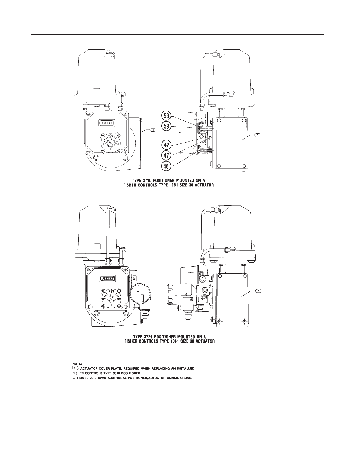
The Fisher Controls Type 3710 pneumatic positioner
and the Type 3720 electro-pneumatic positioner are
used with either diaphragm actuators (spring return) or
piston rotary actuators (spring return or double-action)
as shown in figure 1. These positioners provide a
valve ball or disk position for a specific input signal.
These positioners can easily be configured to provide
single- or double-action output for Fisher Controls
rotary actuators.
The Type 3710 pneumatic positioner accepts a pneu-
matic input signal. The Type 3720 electro-pneumatic
positioner accepts a milliampere (mA), direct current