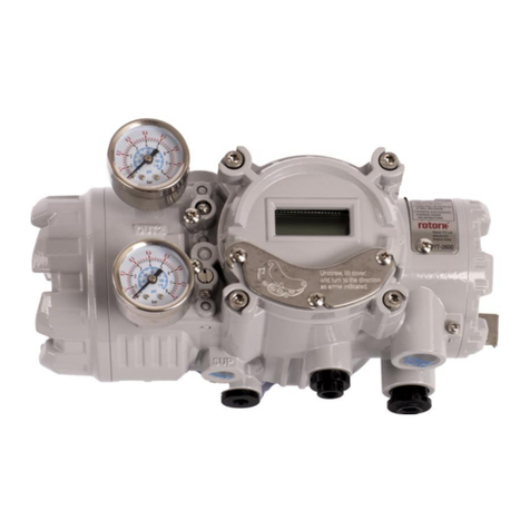
Electro-Pneumatic Positioner
YT-1000 / 1050 series Product Manual
Ver. 1.30 3
2.8.7 YT-1000R (Internal SPTM without LCD) ....................................................................................... 36
2.8.8 YT-1000R (Internal SPTM with LCD) ............................................................................................ 36
2.8.9 YT-1000R (Internal Limit Switch or Limit Switch + SPTM)............................................................ 37
2.8.10 YT-1000R (External SPTM with LCD)....................................................................................... 38
2.8.11 YT-1000R (External Limit Switch).............................................................................................. 39
2.8.12 YT-1050L (Explosion proof construction for internal pressure type)......................................... 40
2.8.13 YT-1050R (Fork Lever type + Explosion proof construction for internal pressure)................... 40
3principle of positioner movement .......................................................................................................... 41
3.1 Linear Positioner................................................................................................................................ 41
3.2 Rotary Positioner ............................................................................................................................... 42
4Installation................................................................................................................................................ 43
4.1 Safety................................................................................................................................................. 43
4.2 Tools for installation........................................................................................................................... 43
4.3 Linear positioner Installation.............................................................................................................. 44
4.3.1 Preparing Bracket for the positioner.............................................................................................. 44
4.3.2 Installation Steps ........................................................................................................................... 45
4.4 Rotary positioner Installation ............................................................................................................. 48
4.4.1 Components................................................................................................................................... 48
4.4.2 Rotary Bracket Information............................................................................................................ 49
4.4.3 Rotary positioner Installation Steps............................................................................................... 50
5Connection - Air....................................................................................................................................... 52
5.1 Safety................................................................................................................................................. 52
5.2 Supply Pressure Condition................................................................................................................ 52
5.3 Piping Condition................................................................................................................................. 52
5.4 Connection –Piping with actuator..................................................................................................... 53
5.4.1 Single acting actuator .................................................................................................................... 53
5.4.2 Double acting actuator................................................................................................................... 55
6Connection – Power ................................................................................................................................ 57
6.1 General.............................................................................................................................................. 57
6.2 Flameproof enclosure type................................................................................................................ 57
6.2.1 Safety............................................................................................................................................. 57
6.2.2 Connection..................................................................................................................................... 58
6.3 Intrinsic safety type............................................................................................................................ 59
6.3.1 Connection..................................................................................................................................... 59
6.4 Internal SPTM (Without LCD)............................................................................................................ 60
6.4.1 Slide Switch ................................................................................................................................... 60
6.4.2 Buttons........................................................................................................................................... 61
6.5 Internal SPTM (With LCD)................................................................................................................. 62
6.6 Internal L/S + SPTM (Without LCD) .................................................................................................. 63
7Adjustments ............................................................................................................................................. 64
