Fisher 4070 User manual

D102589X012
Type 4060 and 4070 Valve Positioners
Contents
Introduction
1. . . . . . . . . . . . . . . . . . . . . . . . . . . . . .
Scope of Manual 1. . . . . . . . . . . . . . . . . . . . . . . . . . . . .
Description 2. . . . . . . . . . . . . . . . . . . . . . . . . . . . . . . . . .
Specifications 2. . . . . . . . . . . . . . . . . . . . . . . . . . . . . . .
Installation
3. . . . . . . . . . . . . . . . . . . . . . . . . . . . . . . .
Positioner Mounting 3. . . . . . . . . . . . . . . . . . . . . . . . . .
Pressure Connections 4. . . . . . . . . . . . . . . . . . . . . . . .
Supply Connection 4. . . . . . . . . . . . . . . . . . . . . . . . . .
Output Connections 5. . . . . . . . . . . . . . . . . . . . . . . . .
Instrument Connection 5. . . . . . . . . . . . . . . . . . . . . . .
Vent 5. . . . . . . . . . . . . . . . . . . . . . . . . . . . . . . . . . . . . . . .
Electrical Connections for Type 4070
Electro-PneumaticPositioners 6. . . . . . . . . . . . . . .
Operating Information
6. . . . . . . . . . . . . . . . . . .
Front Cover and Indicator Cover 6. . . . . . . . . . . . . . .
Cam Adjustment 7. . . . . . . . . . . . . . . . . . . . . . . . . . . . .
Calibration 8. . . . . . . . . . . . . . . . . . . . . . . . . . . . . . . . . .
Pre-calibration 8. . . . . . . . . . . . . . . . . . . . . . . . . . . . . .
Span and Zero Adjustment 8. . . . . . . . . . . . . . . . . . .
Damper Adjustment 9. . . . . . . . . . . . . . . . . . . . . . . . . .
Principle of Operation
9. . . . . . . . . . . . . . . . . . .
Maintenance
9. . . . . . . . . . . . . . . . . . . . . . . . . . . . . .
Troubleshooting 10. . . . . . . . . . . . . . . . . . . . . . . . . . .
Replacing Gauges 10. . . . . . . . . . . . . . . . . . . . . . . . .
Replacing the Pilot valve 10. . . . . . . . . . . . . . . . . . . .
Replacing the Diaphragm 11. . . . . . . . . . . . . . . . . . .
Replacing the I/P Unit Filter 11. . . . . . . . . . . . . . . . . .
Removing the Positioner 11. . . . . . . . . . . . . . . . . . . .
Replacing the Positioner 12. . . . . . . . . . . . . . . . . . . .
Parts Ordering
12. . . . . . . . . . . . . . . . . . . . . . . . . . .
Parts List
12. . . . . . . . . . . . . . . . . . . . . . . . . . . . . . . . .
Figure 1. Type 4070 Electro-Pneumatic Valve Positioner
W7099-1/ IL
Introduction
Scope of Manual
This instruction manual provides installation, operat-
ing, calibration, maintenance, and parts ordering in-
formation for the Type 4060 pneumatic positioner and
the Type 4070 electro-pneumatic positioner. Refer to
Instruction Manual
Form 5452
January 1999 Types 4060 & 4070

Type 4060 & 4070
2
Table 1. Specifications
Available Configurations
Type 4060: Double-acting pneumatic valve posi-
tioner
Type 4070: Double-acting electro-pneumatic valve
positioner
Input Signal(1)
Type 4060: 3 to 15 psig (0.2 to 1.0 bar)
Type 4070: 4 to 20 mA dc
Output Signal(1)
Type 4060 and 4070: Pneumatic pressure as re-
quired by the actuator up to full supply pressure
Air Consumption
See table 2
Air Delivery
See table 2
Performance
See table 3
Supply Pressure(1)
Type 4060: 125 psig (8.6 bar), maximum
Type 4070: 21.8 to 125 psig (1.5 to 8.6 bar)
Operative Temperature Limits(1)
–40 to 185_F (–40 to 85_C)
Housing Classification
NEMA 4, IP66 per IEC 529
Pressure Connections
1/4-inch NPT
Gauge Connections
1/8-inch NPT
Approximate Weight
Type 4060:
Without gauges:
2.4 lbs (1.1 kg)
With gauges:
2.9 lbs (1.3 kg)
Type 4070:
Without gauges:
3.4 lbs (1.5 kg)
With gauges:
3.9 lbs (1.8 kg)
1. This term is defined in ISA Standard S51.1.
Table 2. Positioner Air Consumption and Air Delivery
U. S. Units, SCFM(1)
Supply Pressure, psig
29 58 87 116 145
Air Type 4060 0.19 0.43 0.71 0.98 1.26
Air
Consumption Type 4070 0.22 0.48 0.78 1.08 1.38
Air Delivery 6.9 12.8 18.8 24.7 30.6
Metric Units, normal m3/hr(2)
Supply Pressure, bar
2 4 6 8 10
Air Type 4060 0.31 0.69 1.14 1.58 2.03
Air
Consumption Type 4070 0.35 0.77 1.25 1.74 2.22
Air Delivery 11.1 20.6 30.2 39.7 49.2
1. SCFM—Standard cubic feet per minute (60_F and 14.7 psia)
2. Normal m3/hr—Normal cubic meters per hour (0_C and 1.01325 bar, absolute)
Table 3. Typical Performance for Type 4060 & 4070 Positioner
Characteristic Type 4060 Type 4070
Repeatability ≤0.5% ≤0.5%
Linearity(1) ≤0.5% ≤0.75%
Hysteresis(1) ≤0.75% ≤1.0%
1. This term is defined in ISA Standard S51.1
separate instruction manuals for information on the
actuator, control valve, and other accessories.
Only personnel qualified through training or experience
should install, operate, or maintain these positioners. If
you have any questions concerning the instructions in
this manual, contact your Fisher Controls sales office
or sales representative before proceeding.
Description
The Type 4060 pneumatic positioner and the Type
4070 electro-pneumatic positioner are designed for
use with the Type 585C and 585CR piston actuators.
These positioners mount on the actuator and provide
the desired valve plug position for a specific input sig-
nal. The Type 4060 accepts a pneumatic input signal
and the Type 4070 accepts a 4 to 20 milliampere dc
input signal.
The positioners come standard with built in dampers,
gauge ports and an O-ring sealed housing. The hous-
ing utilizes a unique O-ring seal that can be adjusted
to a sealed or drained position.
Ease of calibration and maintenance are built into the
design with easily accessible span and zero adjust-
ment, and very simple parts replacement.
Specifications
Specifications for the Type 4060 and 4070 valve posi-
tioners are listed in table 1.

Type 4060 & 4070
3
Installation
Typically, the positioner is ordered with the actuator. If
so, the factory mounts and calibrates the valve posi-
tioner and connects the positioner output to the actua-
tor. If the positioner is ordered separately from the ac-
tuator, perform the mounting procedure. Refer to the
appropriate instruction manuals for actuator and valve
installation procedures.
WARNING
Avoid personal injury from sudden re-
lease of process pressure. Before
mounting the positioner on a valve in
service:
DDisconnect any operating lines pro-
viding air pressure or a control signal to
the actuator. Be sure the actuator can-
not suddenly open or close the valve.
DUse bypass valves or completely
shut off the process to isolate the valve
from process pressure. Relieve process
pressure on both sides of the valve.
Drain the process media from both
sides of the valve.
DVent actuator loading pressure and
relieve any actuator spring precompres-
sion.
DUse lock-out procedures to be sure
that the above measures stay in effect
while you work on the equipment.
Positioner Mounting
Remove the storage seal, shown in figure 2, from the
connection block, mount the positioner on the actua-
tor, and make connections to the instrument.
The mounting bracket (key 7B) is used for side mount-
ing the positioner to the actuator yoke. Refer to
figure 3 for part locations.
1. Attach the mounting bracket (key 7B) to the posi-
tioner with the two hex head bolts (key 7D) as shown
in figure 3.
2. Adjust the pin on the feedback lever arm assembly
(key 2) for the appropriate actuator travel (see figure
4). For actuators with 3/4-inch (19.1 mm) travel or
less, use the 30 degree markings. For actuator travels
greater than 3/4-inch (19.1 mm), use the 60 degree
markings.
Figure 2. Storage Seal Location
A7226/ IL
3. Attach the feedback lever arm assembly to the po-
sitioner spindle with the flat head screw as shown in
figure 4.
Note
The stem connector bolts may not be
long enough to permit mounting the
feedback bracket with spacers. If not,
replace the stem connector bolts with
the bolts included in the mounting kit
(key 7G). See the actuator instruction
manual for information on installing the
stem connector.
4. Place the feedback bracket (key 7A), with spacers
(key 7E), over the stem connector bolts so that the
slot in the feedback bracket (key 7A) is opposite the
actuator travel indicator. Fasten the feedback bracket
in place with two hex nuts (key 7F).
5. Position the actuator to its mid-travel position using
a handwheel or manual loading regulator.
Note
In the next step. loosening the cam lock-
ing nut inside the positioner may aid po-
sitioner mounting. See figure 9 for cam
locking nut location.
6. With the actuator at its mid-travel position, insert
the mounting bolt (key 7C) through the slotted hole in
the mounting bracket (key 7B).
7. Attach the bracket to the actuator yoke leg oppo-
site the travel indicator web. Leave the mounting bolt
loose. Be sure the feedback lever assembly pin en-
gages the feedback bracket slot.
8. Position the positioner mounting bracket (key 7B)
so that the feedback lever arm assembly (key 2) is

Type 4060 & 4070
4
Figure 3. Mounting the Positioner on a Type 585C Actuator
BOLTS
MOUNTING BRACKET
BOLT P/P POSITIONER
LEVER ARM ASSY
FEEDBACK BRACKET
CAP SCREWS
SPACERS
HEX NUT
INSTRUMENT GAUGE PORT
1/4 NPT INSTRUMENT PORT
SUPPLY GAUGE PORT
1/4 NPT C1 PORT
C1 GAUGE PORT
1/4 NPT SUPPLY PORT
C2 GAUGE PORT
1/4 NPT C2 PORT
NOTE:
TWO CAP SCREWS (KEY 7G)
ARE INCLUDED IN MOUNTING KIT
IF LONGER LENGTH IS RE-
QUIRED.
1
1
37B9461-A
B2643/ IL
Figure 4. Positioner Feedback Lever Arm Assembly (Key 2)
POSITIONER SPINDLE
(NOT PART OF THE FEEDBACK
LEVER ASSEMBLY)
PIN
BOLT
NUT
FLATHEAD
SCREW
FEEDBACK LEVER ARM
A7194/ IL
parallel to the feedback bracket (key 7A) at mid-travel
position. Tighten the mounting bolt (key 7C).
9. Be sure the feedback lever arm assembly pin does
not pinch, bind, or bend while manually stroking the
actuator.
Pressure Connections
Pressure and gauge connections are shown in figure
5. All pressure connections are 1/4-inch G or NPT fe-
male connectors. Use 3/8-inch tubing or 1/4-inch pipe
for all pressure connections. Gauge ports are 1/8-inch
G or NPT female connectors.
WARNING
Valve positioners are capable of provid-
ing full supply pressure to connected
equipment. To avoid personal injury and
equipment damage, make sure the sup-
ply pressure never exceeds the maxi-
mum safe working pressure of any con-
nected equipment.
Supply Connection
WARNING
Personal injury or property damage may
occur from an uncontrolled process if
the supply medium is not clean, dry, oil-
free air, or non-corrosive gas. Industry

Type 4060 & 4070
5
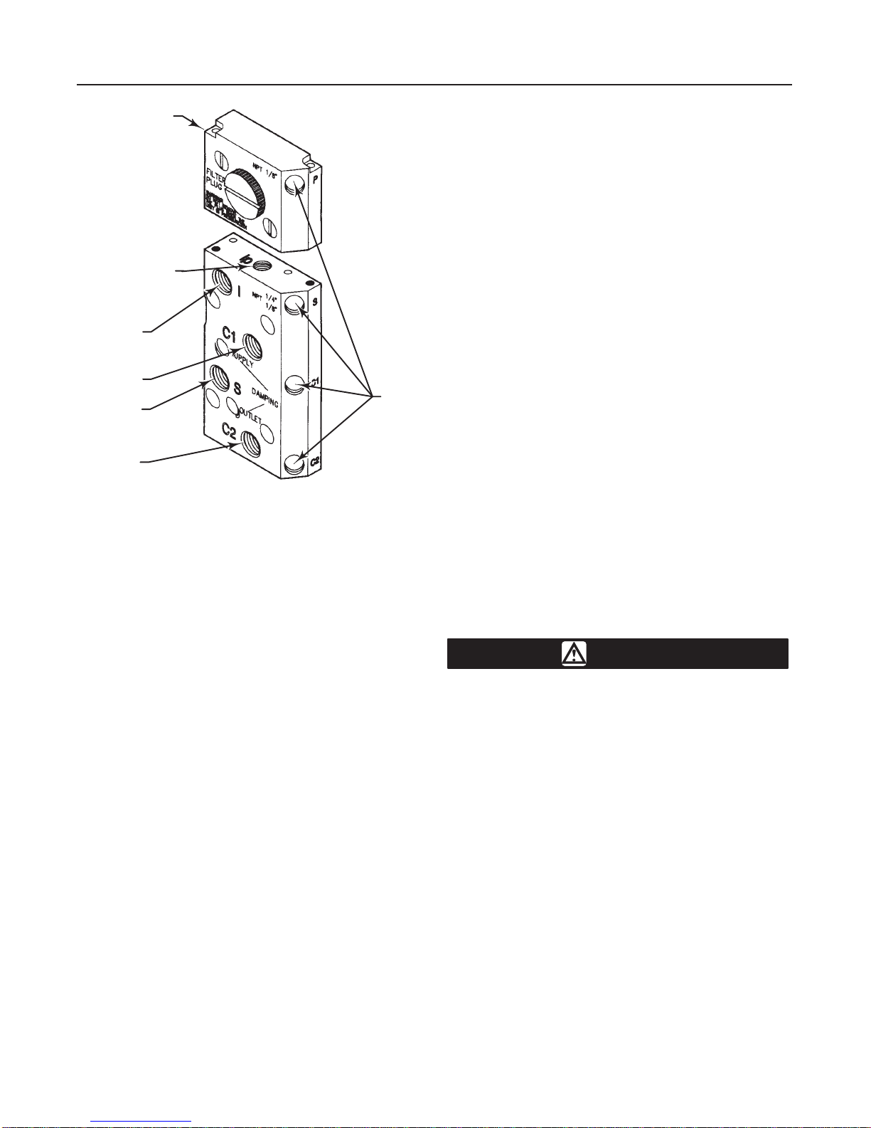
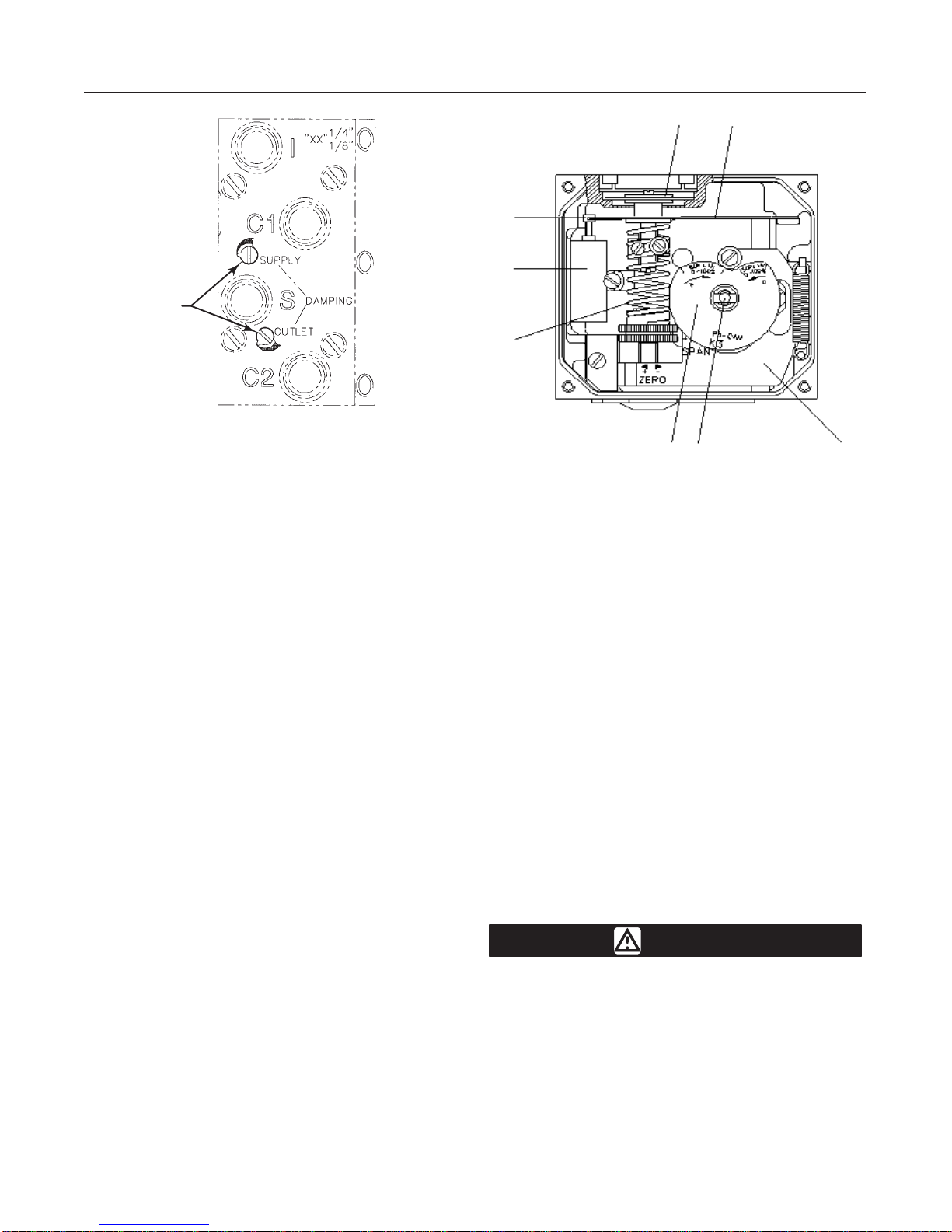
Figure 5. Positioner Pressure and Gauge Connections
INSTRUMENT
CONNECTION
SUPPLY
CONNECTION
OUTPUT
CONNECTION
GAUGE
PORTS
I/P UNIT,
TYPE 4070
OUTPUT
CONNECTION
INPUT SIGNAL GAUGE
PORT FOR TYPE 4060
A7227/ IL
instrument air quality standards de-
scribe acceptable dirt, oil, and moisture
content. Due to the variability in nature
of the problems these influences can
have on pneumatic equipment, Fisher
Controls has no technical basis to rec-
ommend the level of filtration equipment
required to prevent performance degra-
dation of pneumatic equipment. A filter
or filter regulator capable of removing
particles 40 microns in diameter should
suffice for most applications. Use of
suitable filtration equipment and the es-
tablishment of a maintenance cycle to
monitor its operation is recommended.
The supply medium must be clean, dry air or noncor-
rosive gas that meets the requirements of ISA Stan-
dard S7.3-1975. The supply pressure should not ex-
ceed the following limits:
DFor the actuator and positioner, do not exceed
the maximum pressure rating of 125 psig (8.6 bar).
DFor the valve, do not exceed the maximum allow-
able thrust of the specific valve.
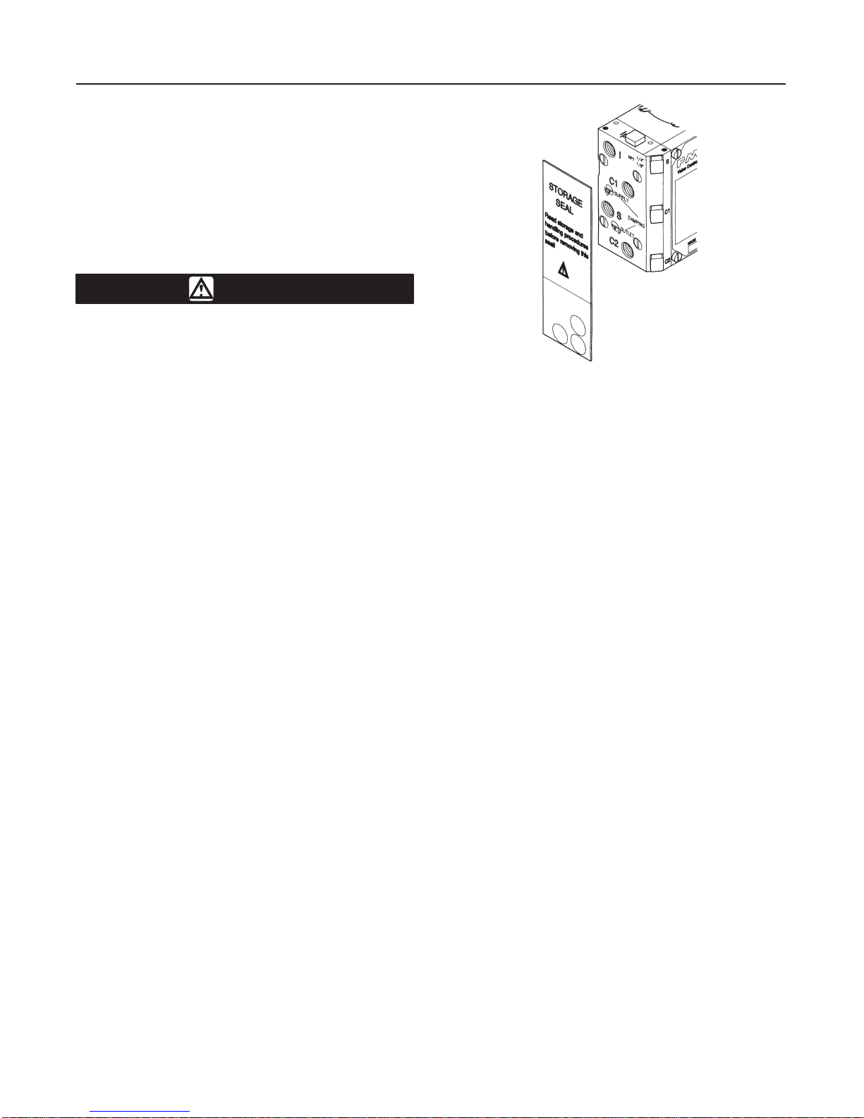
Connect supply pressure to the positioner supply port
S. Gauge port S is sealed with a plug. To install a sup-
ply gauge, unscrew the plug and install an appropriate
gauge.
Output Connections
For Type 585C actuators, connect the positioner out-
put port C1 to the actuator lower cylinder (yoke) con-
nection. Connect output port C2 to the actuator upper
cylinder connection.
For Type 585CR actuators, connect the positioner
output port C1 to the actuator upper cylinder connec-
tion. Connect output port C2 to the actuator lower cyl-
inder (yoke) connection.
For single-acting operation plug port C1 for increasing
signal to open or close. Plug C2 for decreasing (re-
verse) signal to close.
Gauge ports C1 and C2 are sealed with plugs. To
install gauges, unscrew the plugs and install gauges.
Instrument Connection
Connect the control device 3 to 15 psig (0.2 to 1.0 bar)
output to the positioner input port I. If a gauge is de-
sired, remove the plug from port Ipand install an ap-
propriate pressure gauge.
The Type 4070 electro-pneumatic positioner requires
a 4 to 20 milliampere dc current input signal from the
control device. For connections to the Type 4070, re-
fer to the electrical connections section.
Vent
WARNING
If a flammable, toxic, or reactive gas is
to be used as the supply pressure me-
dium, personal injury or property dam-
age could result from fire or explosion
of accumulated gas or from contact with
toxic, or reactive gas. The positioner/ac-
tuator assembly does not form a gas-
tight seal, and when the assembly is en-
closed, a remote vent line, adequate
ventilation, and necessary safety mea-
sures should be used. A remote vent
pipe alone cannot be relied upon to re-
move all hazardous gas. Vent line pip-
ing should comply with local and re-
gional codes and should be as short as
possible with adequate inside diameter
and few bends to reduce case pressure
buildup.
The port (OUT) is for venting the unit. All air from the
positioner, actuator, and I/P unit is vented to atmo-
sphere through this port. This port should be left open

Type 4060 & 4070
6
Figure 6. I/P Unit Storage Seal Location
A7228/ IL
to prevent pressure buildup inside the case and to pro-
vide a drain hole for any moisture that might collect
inside the case. If a remote vent is required, the vent
line must be as short as possible with a minimum
number of bends and elbows.
The vent port (OUT) or the end of a remote vent pipe
must be protected against the entrance of all foreign
matter that could plug the vent. Check the vent period-
ically to be certain it is not plugged.
Electrical Connections for Type 4070
Electro-Pneumatic Positioners
WARNING
For intrinsically safe installations, refer
to the factory drawings or to instruc-
tions provided by the barrier manufac-
turer for proper wiring and installation.
Do not make connections to port I. It is automatically
sealed off and protected.
Remove the storage seal, shown in figure 6, from the
end of the unit to expose the conduit entry. Use the
1/2-inch NPT conduit connection or PG 13.5 (M20)
cable gland for installation of field wiring.
Refer to figure 7 when connecting field wiring from the
control device to the I/P unit. Connect the positive wire
from the control device to the I/P unit positive (+) ter-
minal, and the negative wire from the control device to
the I/P unit negative (–) terminal. Do not overtighten
Figure 7. Typical Field Wiring Diagram
CONTROL
DEVICE
I/P UNIT
A3875-1/ IL
the terminal screws. Maximum torque is 4 lbfSin. (0.45
NSm). Connect the I/P unit grounding terminal to an
earth ground.
To monitor the I/P unit output, install a gauge in gauge
port P. Gauge port Pis sealed with a plug. To install a
gauge, unscrew the plug and install a gauge.
Operating Information
Front Cover and Indicator Cover
The positioner front cover is shown in figure 8. It is
secured to the unit with four captive screws and
sealed with an O-ring. The front cover O-ring can be
looped over notches in the front cover to allow for
drainage.
There are eight locations on the front cover where the
O-ring can be looped. This O-ring system is common
to the pneumatic unit and I/P unit. This unique sealing
system allows for complete sealing or draining of the
units by changing the position of the front cover O-
ring.
The indicator cover is O-ring sealed and secured by a
bayonet coupling. The indicator cover also secures the
identification cover to the front cover.
To remove the indicator cover, turn it slightly counter-
clockwise until it loosens. The identification cover and
indicator cover O-ring are now removable. When
installing the indicator cover and identification cover,
make sure that the indicator cover O-ring is properly
engaged.

Type 4060 & 4070
7
Figure 8. Front Cover and Indicator Cover
IDENTIFICATION
COVER INDICATOR
COVER
FRONT
COVER
O-RING
NOTCH
FRONT COVER SHOWN WITH O-RING LOOPED
OVER NOTCHES TO PERMIT DRAINING
INDICATOR
COVER O-RING
B2644/ IL
FRONT
COVER
CAM LOCKING NUT
SCREW
CAM
CORRECT
INCORRECT
CAM
FOLLOWER
1/16-INC H
(1–2 mm)
Figure 9. Cam Adjustment
CAM POSITIONED FOR A FAIL-OPEN
ACTUATOR WITH 3/4-INCH (19.1 MM)
OR LESS TRAVEL
B2645/ IL
Cam Adjustment
Refer to figure 9. With the cover and indicator re-
moved, loosen the screw and turn the cam locking nut
counterclockwise until the cam loosens.
The cam has two lobes. The 30 degree lobe is used
for actuator travels of 3/4-inches (19.1 mm) or less.
The 60 degree lobe is used for actuator travels of
greater than 3/4-inch (19.1 mm). The cam also may be
turned over. Each lobe is stamped either direct (D) or
reverse (R). Refer to table 4 for cam installation infor-
mation.
Install the cam so that the follower will ride on the cor-
rect lobe listed in table 4. For fail-open actuators, the
follower will ride on the cam lobe to the right of the
follower. For fail-close actuators the follower will ride
on the cam lobe to the left of the follower.

Type 4060 & 4070
8
Table 4. Cam Position Information
Actuator Travel Cam
Lobe
Cam Orientation for Actuator
Failure Mode
Actuator
Travel
Lobe Fail Open Fail Close
greater than
0.75 inch (19.1 mm) 60_D R
less than or equal to
0.75 inch (19.1 mm) 30_D R
To secure the cam, make sure the screw is backed
out from the locking nut. Tighten the locking nut finger
tight then tighten the screw. Install and adjust the indi-
cator and reinstall the cover.
Calibration
Pre-calibration
Ensure that the cam is installed correctly for the ap-
propriate actuator travel and failure mode. Refer to the
“Cam Adjustment” procedure. Also ensure the pin on
the feedback lever arm assembly is positioned correct-
ly for the appropriate actuator travel. Refer to step 2 in
the “Positioner Mounting” procedure.
With the two locking screws facing you, as shown in
figure 10, there should be at least one coil of the feed-
back spring above the screws. However, the end of
the feedback spring should not touch the spring guide.
To adjust the spring, loosen the two locking screws.
Hold the two locking screws in place while rotating the
feedback spring. Tighten the locking screws.
Zero and Span Adjustment
Refer to figure 10.
1. Remove the positioner front cover.
2. Apply supply pressure to the positioner.
3. Set the input signal to the 0% value and wait for the
unit to reach steady state.
4. Rotate the zero adjustment until the actuator stem
is at its starting position. Zero is adjusted by turning
the silver thumb wheel located on the lower arm or
externally with a screwdriver through the zero adjust-
ment opening.
5. Slowly increase the input signal until the input
reaches the 100% value. Observe the actuator travel
and valve position as the input increases. Note the
actuator travel at 100% input signal.
6. Set the input signal to the 0% value.
Figure 10. Positioner Span and Zero Adjustment Locations
SPAN
ADJUSTMENT
SPRING GUIDE LOCKING SCREW
ZERO
ADJUSTMENT
LOWER ARM
ZERO ADJUSTMENT
COVER
A7229/ IL
7. If necessary, loosen the locking screw and adjust
the span as follows (span is adjusted with the brass
colored thumb wheel located on the feedback spring):
DIf the actuator travel recorded in step 5 is short of
the desired travel at 100% input signal, rotate the span
adjustment to the left to increase span. Tighten the
locking screw.
DIf the travel recorded in step 5 reaches the de-
sired travel before the input signal reaches the 100%
value, rotate the span adjustment to the right to de-
crease span. Tighten the locking screw.
After the span adjustment, recheck to be sure the end
of the feedback spring is not touching the spring guide.
8. After a span adjustment, recheck the zero and ad-
just if necessary.
9. Repeat steps 4 through 8 as necessary to achieve
correct actuator travel.

Type 4060 & 4070
9
DAMPER
ADJUSTMENTS
Figure 11. Damper Adjustment
A7230/ IL
10. Replace the positioner front cover.
11. If you used the zero adjustment opening, remem-
ber to install the zero adjustment cover to ensure the
unit is sealed.
Damper Adjustment
The built in dampers provide a simple means of ad-
justing the actuator travel speed. The damper adjust-
ments are located on the connecting block as shown
in figure 11. For maximum actuator travel speed adjust
dampers to the minimum damping position.
Double acting actuators—adjust only the OUTLET
damper. Set the SUPPLY damper to the minimum
damping position.
Single acting actuators—adjust both dampers for
desired operation.
Principle of Operation
Refer to figure 12.
The pneumatic positioner operates on a force balance
principal. Force is originated by the signal pressure
transmitted through a diaphragm on to the balance
arm. The opposing force is achieved through the feed-
back spring and is proportional to the position of the
lower arm. The lower arm position is determined by
the position of the cam which is secured to the spindle
and connected to the actuator shaft thus providing the
feedback from the actuator/valve. When these two
forces are equal, the balance arm and the spool in the
Figure 12. Principle of Operation
12
3
4
56
7
8
A7231/ IL
pilot valve is in a neutral position—the complete unit is
in a balanced position. Air is supplied to the pilot valve
through port S, and controls the air flow through ports
C1 and C2
Assume an equilibrium position. An increasing control
pressure deflects the diaphragm 1down, compressing
the feedback spring 3. The balance arm 2moves the
spool 7in the pilot valve 8furnishing supply air to the
actuator, while at the same time air is exhausted from
actuator and is vented to atmosphere through the pilot
valve and the OUT port.
With increasing supply air, the linear motion of the ac-
tuator stem rotates the positioner spindle 6. The
spindle and cam 5rotation forces the lower arm 4up-
wards compressing the feedback spring 3. This motion
continues until the two forces are equal and the unit is
in an equilibrium position.
Maintenance
WARNING
Avoid personal injury from sudden re-
lease of process pressure. Before
mounting the positioner on a valve in
service:
DDisconnect any operating lines pro-
viding air pressure or a control signal to
the actuator. Be sure the actuator can-
not suddenly open or close the valve.

Type 4060 & 4070
10
DUse bypass valves or completely
shut off the process to isolate the valve
from process pressure. Relieve process
pressure on both sides of the valve.
Drain the process media from both
sides of the valve.
DVent actuator loading pressure and
relieve any actuator spring precompres-
sion.
DUse lock-out procedures to be sure
that the above measures stay in effect
while you work on the equipment.
DFor Type 4070 electro-pneumatic
positioners in intrinsically safe areas,
current monitoring during operation
must be with an approved meter for haz-
ardous areas in order to avoid personal
injury or property damage caused by an
explosion or fire.
Troubleshooting
Signal change has no effect on the actuator posi-
tion.
—Check indicator and screw.
—Check air supply to positioner and tubing to the ac-
tuator.
—Check input signal to positioner.
—Check diaphragm for damage or leakage.
—Check pilot valve function.
—Check cam for correct setting.
—Check I/P output
Signal change results in actuator running to end
positions.
—Check coupling between positioner and actuator.
—Check cam position and locking screw.
—Check input signal.
Inaccurate positioning.
—Dirty or worn pilot valve.
—Defective or leaking diaphragm.
Figure 13. Pilot Valve Assembly
SCREW
PILOT VALVE
ASSEMBLY
SPOOL SPOOL GROVE
BALANCE ARM
LEAF SPRING
A7232/ IL
—Input signal fluctuates.
—Incorrect sizing of actuator.
—Valve/actuator “stiction”.
—High valve/actuator breakaway torque.
—Loose cam.
Replacing Gauges
1. Shut off supply pressure and process lines to the
positioner.
2. Remove the defective gauge.
3. Coat the threads of the replacement gauge with a
sealant (Zink plate No. 770 or equivalent).
4. Screw the replacement gauge into the gauge port.
5. Apply supply pressure to the positioner. Using a
soap solution, check around the ports and connections
for leaks.
Replacing the Pilot Valve
Refer to figure 13 to remove the pilot valve for clean-
ing or inspection.
1. Remove the screw and carefully lift out the com-
plete pilot valve assembly.
2. Gently remove the spool from the block and clean
the parts, using mentholated cleaner or similar. Blow
the parts dry with compressed air. If the parts show
signs of wear, replace the assembly.
Note
Mixing spool valves and valve bodies
may result in very high bleed rates and
poor performance.

Type 4060 & 4070
11
Figure 14. Diaphragm
DIAPHRAGM COVER SCREWS
SCREW WASHERS DIAPHRAGM
A7233/ IL
3. Check the O-rings, then secure and install the pilot
valve assembly to the positioner housing and secure it
with the screw. Make sure that the leaf spring on the
balance arm is properly fitted in the spool groove.
4. Check again to insure smooth operation of the as-
sembly.
Replacing the Diaphragm
Refer to figure 14. For Type 4070 electro-pneumatic
positioners, the I/P unit must be removed to access
the diaphragm.
1. Loosen the four screws and remove the diaphragm
cover.
2. Loosen the screw that secures the diaphragm. Re-
move the diaphragm and washers.
When installing the diaphragm make sure to place one
washer on each side of the diaphragm. Make sure that
the raised circle on the washers is facing the dia-
phragm.
3. Install the screw and tighten.
4. Check the O-ring on the diaphragm cover, then
install and secure the cover with the four screws.
Figure 15. Filter Replacement
FILTER
O-RING
FILTER PLUG
A7234/ IL
Replacing I/P Unit Filter
CAUTION
Do not operate the unit without filter
and filter plug installed. Do not attempt
to unscrew filter plug while positioner is
pressurized.
The I/P unit on the Type 4070 positioner is equipped
with a built in secondary filter located on the side of
the I/P unit.
For replacement or inspection, refer to figure 15. Make
sure the positioner unit is not pressurized, then un-
screw the filter plug. Remove the filter and install a
new one into the filter plug . Check the condition of the
O-ring and filter compartment. If moisture is found,
check upstream filters and oil-and-water separators.
Moisture can cause the I/P unit to fail. Reinstall the
filter plug.
Removing the Positioner
1. Shut off supply pressure and process lines to the
positioner.
2. Disconnect pneumatic and, if necessary, electrical
connections.
3. Remove the screws that attach the positioner to
the mounting bracket and remove the positioner.

Type 4060 & 4070
12
Replacing the Positioner
1. Replace the positioner on the actuator by perform-
ing the mounting and connection procedures in the
“Installation” section.
2. Calibrate the positioner by performing the proce-
dures in the “Calibration” section.
Parts Ordering
When corresponding with your Fisher Controls sales
office or sales representative about this equipment,
refer to the serial number found on the serial tag at-
tached to the positioner body. Also, specify the com-
plete 11-character part number from the following
parts list when ordering replacement parts.
Parts List
Key Description Part Number
1 Positioner
Type 4060 pneumatic positioner 18B3125X012
Type 4070 electro-pneumatic positioner
w/FM and CSA intrinsic safety approvals 18B3126X012
w/CENELEC intrinsic safety approvals 18B3127X012
2 Feedback Lever Arm Ass’y 18B2837X012
3 Instrument Gauge
Triple scale 0–30 psi/2 bar/0.2 MPa 11B4036X012
4 Supply Gauge
Triple scale 0–160 psi/11 bar/1.1 MPa 11B4036X032
5 Output Gauge
Triple scale 0–160 psi/11 bar/1.1 MPa 11B4036X032
6 Output Gauge
Triple scale 0–160 psi/11 bar/1.1 MPa 11B4036X032
– – – Test connections (4 req’d) 1N908899012
– – – Pilot Valve 18B2838X012
7 Mounting kit
For size 25 actuators 18B3128X012
For size 50 actuators 18B3129X012
For information, contact Fisher Controls:
Marshalltown, Iowa 50158 USA
Cernay 68700 France
Sao Paulo 05424 Brazil
Singapore 128461
Printed in U.S.A.
EFisher Controls International, Inc. 1999; All Rights Reserved
Fisher, Fisher-Rosemount, and Managing The Process Better are marks owned by Fisher Controls International, Inc. or Fisher-Rosemount Systems, Inc.
All other marks are the property of their respective owners.
This manual suits for next models
1
Table of contents
Other Fisher Valve Positioner manuals
Popular Valve Positioner manuals by other brands

Burkert
Burkert 8692 Supplement to operating instructions

SMC Networks
SMC Networks IP8101 Series Operation manual

Absolute Process Instruments
Absolute Process Instruments APD 3280 quick start guide

Heimeier
Heimeier Thermolux K Consumer information

VAC
VAC V200 POSITIONER Fine Tuning

MIEPL
MIEPL YTC YT-3400 Series product manual

Pepperl+Fuchs
Pepperl+Fuchs PMI14V-F112-IO Series manual

PI
PI PIMAG V-412.xx6025E0 Series user manual

halstrup-walcher
halstrup-walcher PSE2 C Series instruction manual

Vestil
Vestil MWP-220 instruction manual

Baelz Automatic
Baelz Automatic BA 7020 operating instructions

Spirax Sarco
Spirax Sarco SP2 Installation and maintenance instructions