Mount-It! MI-4461 User manual
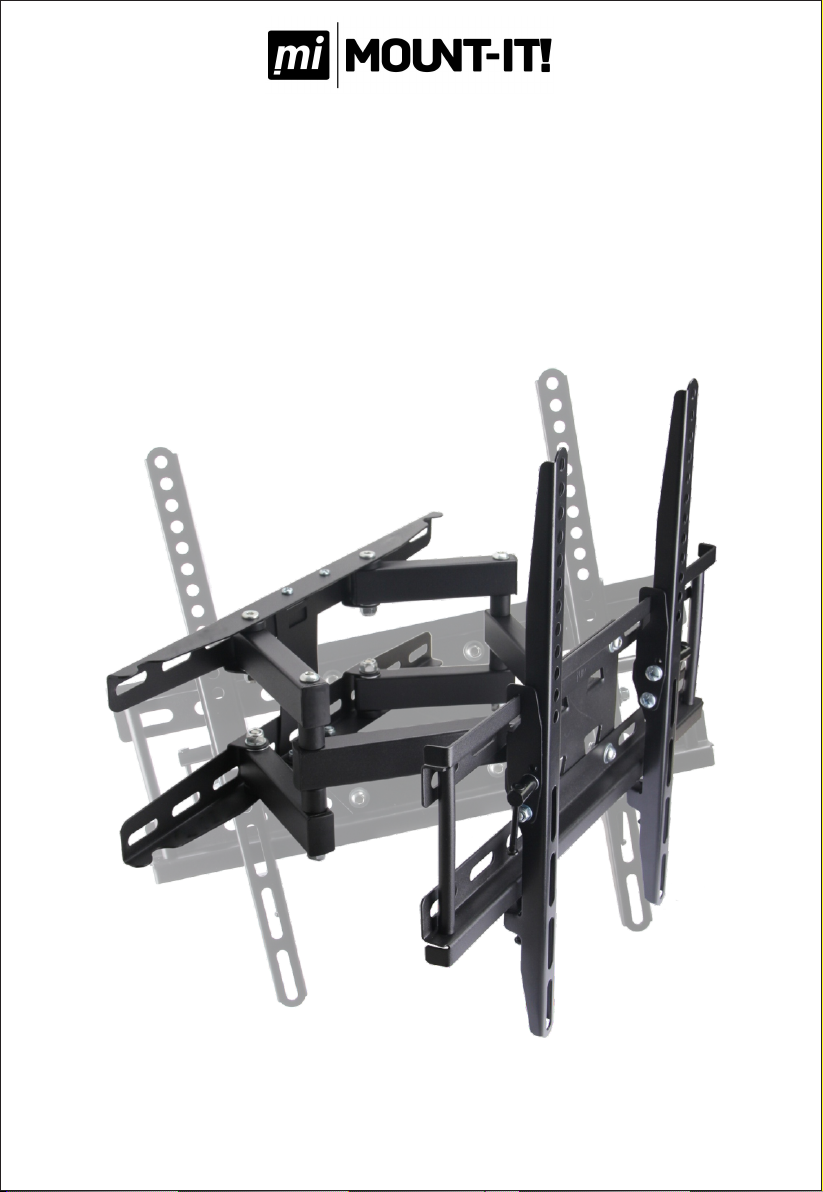
LCD/LED/Plasma
Wall Mount Manual

Product Overview:
The mount arculang arm mount features a flat profile of 2.75" from the wall to the back of your display
and a full extension of 13.5" from the wall as well as +15 degrees of lt. The mount is constructed with
100% High Grade Steel providing a sturdy and reliable mount. The mount’s wall plate allows for quick and
easy installaon and will support stud applicaons up to 16" apart. The mount will fit the majority of LCD,
LED and Plasma Displays up to 60”. Most LCD and Plasma displays 60” and smaller conform to the VESA
Standards. However, this mount will support most odd sized hole paerns that do not conform to the VESA
Standards.
Key Features:
Covers Hole Paerns 15.75" Horizontal by 15.75" Vercal and Up to VESA 400x400mm
Extends to 13.5" and Collapses To 2.75" From The Wall
0 - 15° of Downward Tilt
Safety Screw to Prevent Accidental Li off
Double Stud Installaon
Installaon Hardware Included
2
Quantity
1
4
4
8
4
4
4/4
4
4
4
4
4
4
4
1
2
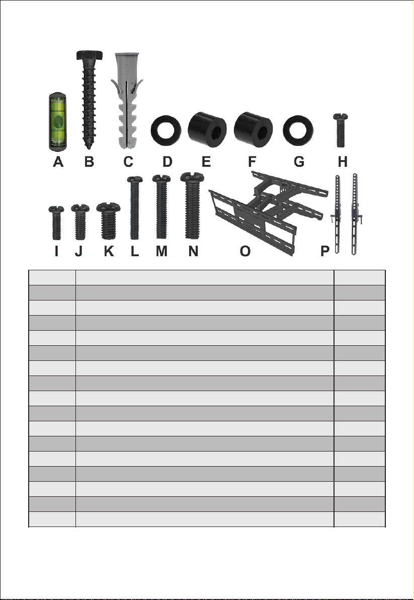
Part
A
B
C
D
E
F
G
H
I
J
K
L
M
N
O
P
Description
Removable Bubble Level
6x50mm Lag Bolts
S10x50mm Concrete Anchors
8mm Washer
6x13 Plastic Spacer
8x15mm Plastic Spacer
5mm/6mm Washer
M4 12mm Screw
M5 12mm Screw
M6 12mm Screw
M8 12mm Screw
M5 30mm Screw
M6 30mm Screw
M8 30mm Screw
Mount
TV Arm Brackets
3
Up To 15.75" Horizontal by 15.75"
Vertical or VESA 400x400mm
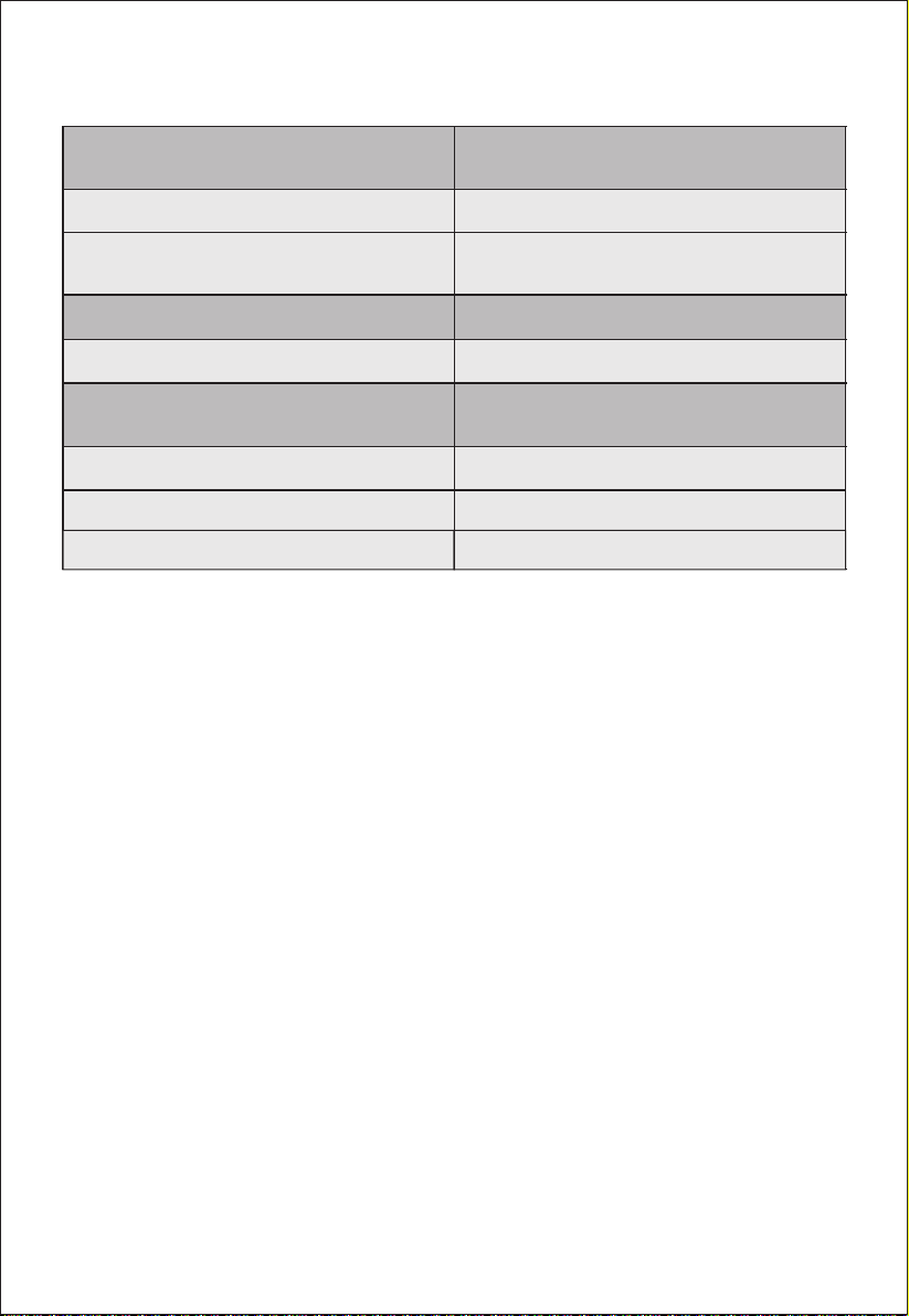
*Hole Pattern Coverage/Supported VESA Patterns:
Unit Weight:
Unit Materials:
Tilt Range:
Total Swivel Rotation:
Arm Extension/Collapsed:
Wall Plate Dimensions:
TV Plate Dimensions:
TV Arm Bracket Height:
Net: 8.8LBS Gross: 9.5LBS
Arms, Wall Plate and TV Plate:
100% High Grade Steel
0 - 15°
130°
Fully Extended: 13.5"
Fully Collapsed: 2.75"
16.9x5.6"
16.9x5.6"
16.4"
4

Installaon instrucon:
Secon 1: Wood Stud Installaon:
2x4 Stud Wall
(16-24" Spacing)
Outlet located
next to stud
5
Note: Please read all installaon instrucons carefully before installaon.
For standard wood stud installaon please start at Secon 1: Wood Stud Installaon.
For Concrete/Mortar installaons please refer to Secon 2: Concrete/Masonry Installaon.
1.Locang a Stud: First you will need to locate the stud in the wall you wish to mount your TV to. If you
know how to locate your stud please connue to Step 2. If you do not know how to locate your stud
please connue.
Finding a Wooden Stud in Your Home: One quick way to find a wall stud is to find a power outlet on the
wall. Wall outlets are normally located next to a stud. The easiest way to confirm the locaon of a stud is
with an electronic stud finder, which you can purchase at any
hardware store.
Once you find an inial stud, other wall studs are typically
located in the wall every 16” . Please note in some homes
they are constructed with studs every 24”. Addionally, many
walls have “non-standard” studs located next to doors,
windows and fireplaces. To get the best support for your
mount, it is important that you put the mounng screws for
your wall plate into the center of the wall stud. If it is difficult
to determine the exact center of the stud with your stud
finder, you can get the exact locaon of the stud using a thin
nail and hammer. With the Hammer,pound the thin nail into
the wall in the area of the stud. If the nail is to the side of the stud, it will go through the drywall and easily
into the empty space in the wall. If the nail is on the stud, once it goes through the drywall, it will not go
into the wall easily as it is hing the wood of the stud. Keep repeang this process in the area of the stud
unl you can tell exactly where the stud starts and ends. The middle of these two points is the center of
the stud.
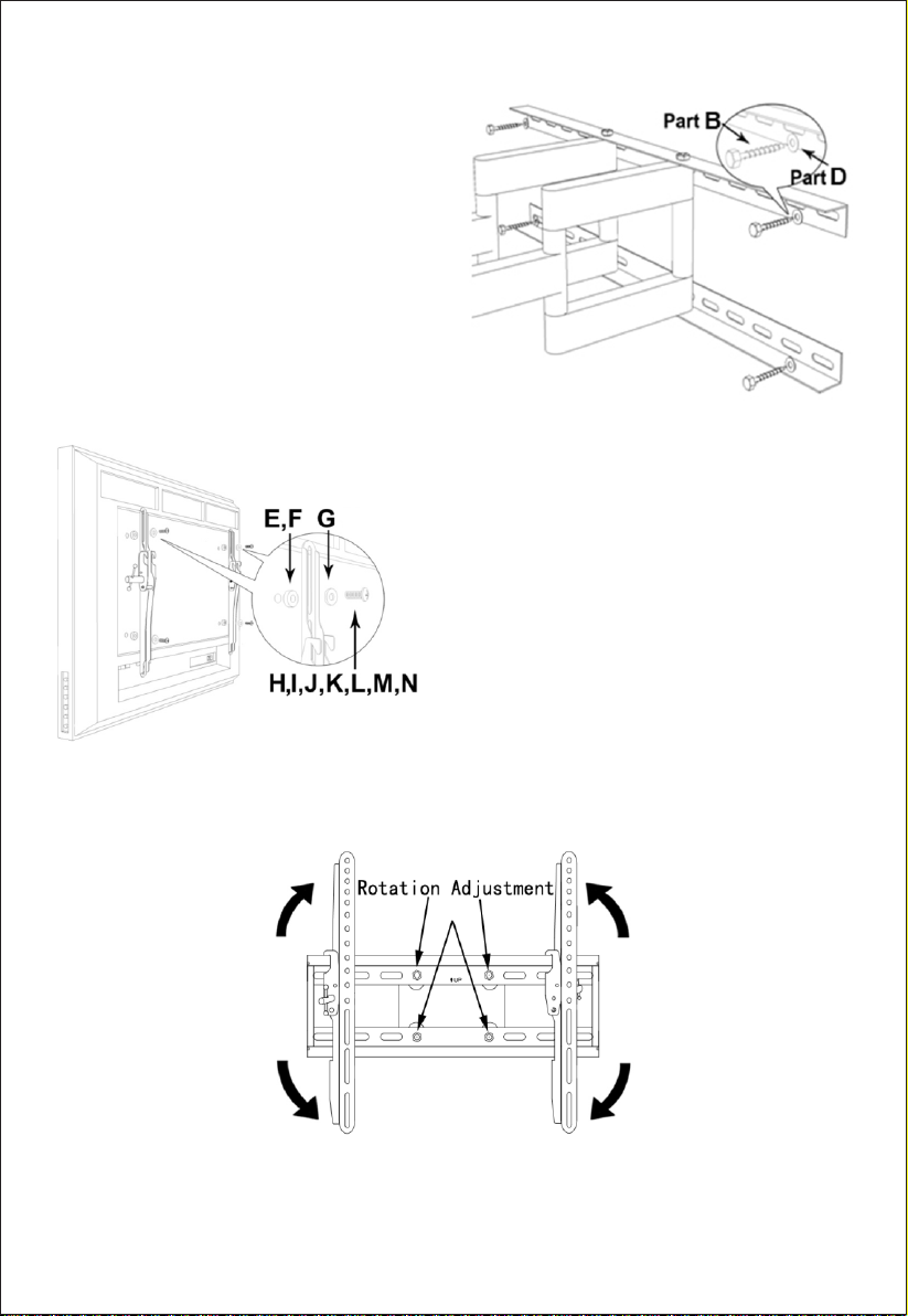
2.Mark and Pre-Drill Installaon Points: Once
you have located your studs, Mark the holes
locaons where you intend to drill, assure that
they are level with one another. Use a 5mm drill
bit to pre-drill four holes to a depth of 2”. If you
do not have a metric drill bit a 3/16” drill bit will
work as well.
6
4. Installing Arm Brackets Onto The Back of Your Display:
Once you locate the appropriate screws, aach the two
arm brackets to the back of the display. To aach the arms
use the proper bolt and washer for each of the four
mounng holes. In the event your display has recessed
holes or a curved back, your hardware pack includes
plasc spacers to fill the gaps. These plasc spacers are
not necessary for most installaons.
3. Aaching The Mount to Your Wall: Once the four
holes are pre-drilled, affix the wall plate to the wall
with all four lag bolts and washers into the wall. The
included plasc anchors DO NOT need to be used for
wood stud installaon.
Note on locang hardware to mount arms to your
display: If your d isplay does not come with the
mounng screws in the back of the display, check the
original desk stand as in some cases the same screws to
hold the desk stand are used also to mount your
display. If neither of these opons work, the hardware
pack included with your mount contains several of the
most common sized screws for mounng your arm
brackets to your display.
5. Adjusng The Rotaon: The rotaon adjustment allows the TV to remain level when the TV is pulled out or flat against
the wall. To ulize this adjustment there are four bolts in the center of TV plate which must be slightly loosened to rotate
the display from side to side.
7
6. Aaching Your Display to The Wall Plate: Aer installing the wall plate and tesng to ensure that it is aached
securely and aaching the arms to the back of the display, it is me to aach your display to the wall. This step may
require two people, aach the hook to the top lip of the wall plate. Once the hooks are securely set onto the wall plate
you can now let the boom of the display rotate back and it will simply hang on the mount.
7. Securing Your Display: The mount ulizes a set screw aached to the
boom of each one of the arm brackets. To secure the arm bracket to
the TV plate, locate the set screw on the boom of the arm then ghten
in a clockwise moon unl ght. This screw ensures that your display
will not li off of the mount.
8. Adjusng Your Tilt: To adjust the lt posion on your display you will
need to loosen the Phillips screw on the side of each one of the arm
brackets, set the desired lt and then ghten the arms back up. You can
loosen the screws slightly so that it will sll hold while you adjust your
lt, once you have set the desired angle of lt you can then fully ghten
the screws.
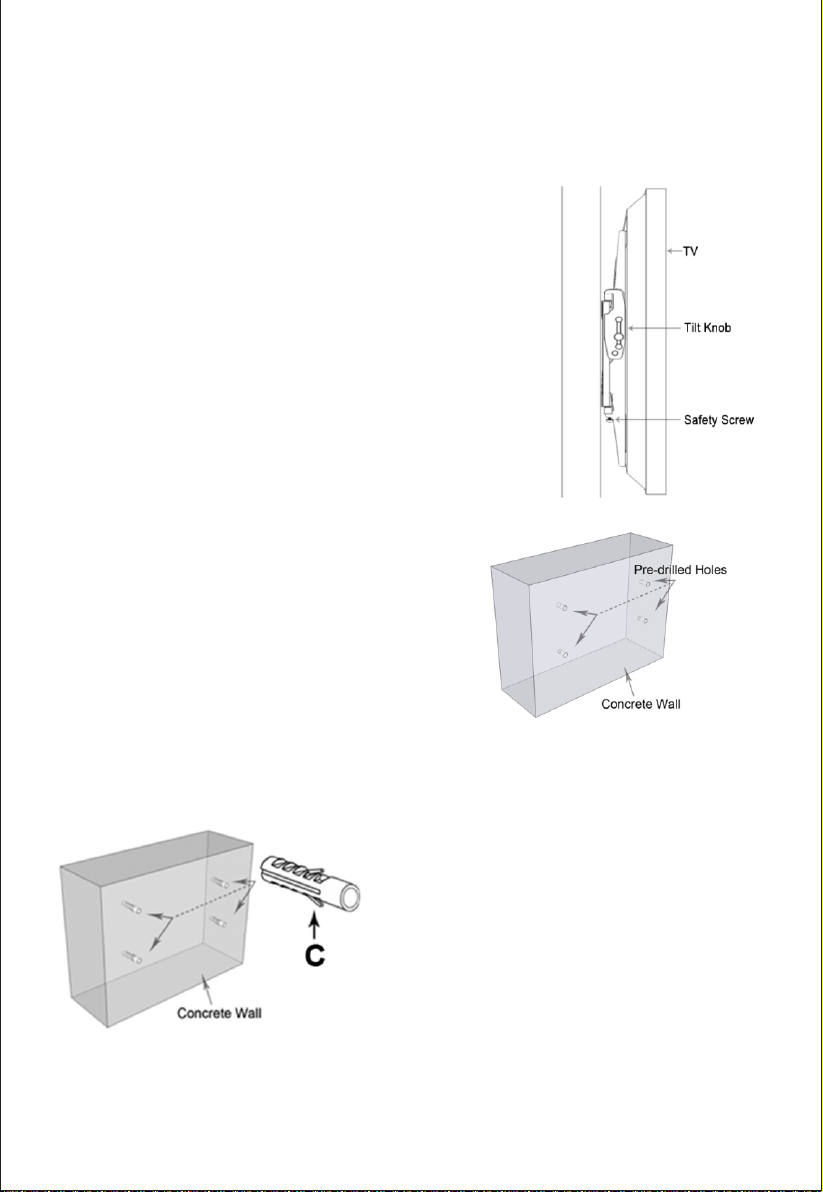
Secon 2: Concrete and Masonry Installaon:
1. Mark Installaon Points: Once you have selected the
locaon you want the mount to be, mark the exact locaon
where the anchors and lag bolts will be installed. Next, pre-
drill the holes using a masonry 10mm drill bit to a depth of 2”
then insert the supplied anchors. If you do not have a metric
drill bit a 3/8" drill bit will work.
Drilling Into Concrete: When drilling into concrete or masonry,
you have to use a special masonry drill bit which you can
purchase at your local hardware store, using a standard drill bit
will not penetrate the concrete and it will just dull your drill
bit. It is not recommended to drill and mount into concrete block or mortar joints. If mounng into concrete or
masonry we recommend using all of the supplied plasc anchors and lag bolts for maximum support. The supplied
plasc anchors are rated for use up to 165LBS, but if you prefer you can go to your local hardware store and purchase
metal concrete anchors.
2. Aaching The Mount to Your Wall:
Once the holes are pre-drilled, insert all plasc anchors,
Then affix the wall plate with the four supplied lag bolts and
washers into the wall.
Revision date: 04/12/2016
Other Mount-It! TV Mount manuals


