Mountway Aquila User manual

Operating instructions
aquila™
bath lift
telecare-enabled

Operating Instructions
Please ensure both yourself and any helpers read these instructions carefully before using
your bath lift. These operating instructions should be retained for future reference.
This bath lift is designed and manufactured to assist individuals in getting in and out of the bath. It
should not be used for any other purpose. Do not use it in combination with other lifting or moving
devices. If you are unable to get out of the bath unaided, do not bathe without someone on call to
help in an emergency.
Contents
Unpacking the bath lift
1. Unpacking the bath lift . . . . . . . . . . . . . . . . . .3
Before you start
2.Chargingthebattery.....................3
3. If you have a telecare -enabled
bathlift..................................4
4. Preparing the bath for installation . . . . . . . .5
5. Installing the bath lift . . . . . . . . . . . . . . . . . . . .5
Using the bath lift
6. Connecting the hand control . . . . . . . . . . . .6
7.Usingthebathlift........................7
Removing and storing the bath lift
8. When the bath lift is not in use . . . . . . . . . . .8
9. Removing the bath lift from
thebath.................................8
10.Cleaning................................9
Warranties, maintenance & servicing
11. Maintenance and servicing . . . . . . . . . . . . .9
12.Warranty..............................10
Symbols
13.Symbols..............................10
Technical data
14.Technicaldata........................11
Troubleshooting
15.Troubleshooting......................13
Parts list
16.Accessories...........................16
17.Partslist..............................18
2

1. Unpacking the bath lift
Open the packaging and ensure the bath lift is not damaged and that all parts are included. If it has
been damaged in transit, or parts are missing, contact your supplier immediately.
Inside the box you will nd:
• A bath lift, complete with two side aps and hand control attached (see g 1)
• Side ap protectors x 2 (see g 1)
• A battery (see g 2)
• Battery charger with charging cradle attached (see g 2)
We suggest that the bath lift is always separated and carried as two lighter, individual sections.
i) Upon opening the packaging, pick up the backrest assembly (see g 1) until it is free of the seat
unit (see g 1).
ii) Place the backrest assembly carefully to the side out of the way.
iii) Now lift the seat unit out of the packaging.
Before installing or using the bath lift for the rst time, ensure you charge the battery (see section 2,
“Charging the battery ” below).
2. Charging the battery
Before rst operation of your bath lift or after long periods of non-use (typically 7-10 days),
fully charge the battery as follows. A at battery will take up to 2 hours to charge.
i ) Slide the battery into the track on the charging cradle until it clicks into place (see g 2).
ii ) Plug the charger into the mains socket outside the bathroom and switch on the electricity supply.
iii) The light indicator on the charger box will initially ash in a quick sequence of red, green, red,
green, before a constant red light appears to indicate charging is in progress (see g 2).
iv ) When the battery has been fully charged, the red light on the charger box turns to a constant
green light, which indicates the battery is ready for use, and can remain continuously on charge
until you are ready to take your bath.
v ) When you are ready to use your fully charged battery (see paragraph iv), switch o the mains
socket or remove the charger from the mains socket, then ensure you disconnect the battery
from the charging cradle. (This prevents the battery discharging and will reset the charger ready
for its next use.)
We recommend charging the battery after each bath wherever possible and leaving it on charge
until your next bath. The battery cannot be overcharged.
3
Diagrams for operation and explanation of use are on the
fold-out diagram sheet attached to the rear of this booklet

NOTE:
• Do not charge in the bathroom or any humid area. Always charge in a dry area, ensuring your
hands are dry rst.
• Do not cover the battery or charger whilst charging.
• Always charge on a hard surface.
• During charging, the temperature of the charger box may exceed 40oC but will gradually
decrease once the constant green light on the box appears. Users with sensitive/damaged
skin should take care and allow approximately 3 hours from start of charging before handling
the box.
• Ensure that no metal objects touch the contacts on the battery, as this will damage the battery.
• Use only the Mountway charger supplied to charge the battery and for no other purpose.
3. If you have a telecare-enabled bath lift
The telecare-enabled bath lift has been designed to integrate with the Tunstall Lifeline 400, 4000+
and Connect+ units. The telecare-enabled bath lift can be added to an existing monitoring solution
or as part of a new installation to suit individual needs.
If you have a telecare-enabled bath lift, you will nd a telecare-enabled battery inside your bath lift
box rather than the standard battery (see g 3).
Programming the telecare-enabled bath lift to Tunstall 400, 4000+ and Connect+ home
units
i ) Press and hold down the green cancel key located on the Lifeline unit (see g 4) until it bleeps
(approx. 5 seconds), then release the green cancel key and the Lifeline unit will bleep twice. The
red alarm button will ash slowly.
ii ) Press the green cancel key again until the Lifeline unit bleeps, then release the cancel key and
the Lifeline unit will bleep twice. The red alarm button will now ash rapidly.
iii) Press the red button on the end of your bath lift’s telecare-enabled battery (see g 3) and a red
light will illuminate at the end of the battery. The Lifeline unit will bleep to conrm acceptance.
iv) Press and release the green cancel key on the Lifeline unit and the unit will bleep.
v) Make a test call using the programmed telecare-enabled battery (see g 3) by pressing its red
button and ensure it raises an alarm call.
Making an alarm call
i ) To raise an alarm while using the bath lift, press the red button on the end of the battery
(see g 3). This will allow you to talk to the control centre operator ‘hands free’using the
powerful speaker and microphone of the Lifeline 400, 4000+ and Connect+.
ii ) The control centre operator will summon the appropriate assistance from your carer, warden or
emergency services.
4

NOTE:
An alarm call cannot be raised unless a Tunstall Lifeline 400, 4000+ or Connect + home unit is
installed in your home and the telecare-enabled battery is programmed correctly to this home
unit (see section “Programming the telecare-enabled bath lift to Tunstall Lifeline 400, 4000+ and
Connect+ home units”above).
4. Preparing the bath for installation
i ) Remove any non-slip mats from the bath.
ii ) Ensure the bottom of the bath is clean and smooth, with no oil or bath cleaner residues that will
prevent the suction feet from sticking.
iii ) The suction feet may not be suitable in baths that have been re-enamelled or that have rippled
or textured surfaces. For some baths with rippled or textured surfaces, the front suction feet
(see g 7) can be relocated to the middle of the bath lift base frame, to clear the bath’s textured
area. A centre sucker xture kit is available for this purpose (see section 16, “Accessories”).
iv ) It is essential that the side aps do not catch under any obstructions such as integral bath
handles, handrails, soap dishes and taps when rising. If your bath has integral handles, hook the
side ap protectors over them (see g 1 and g 5) to prevent the side aps from catching.
5. Installing the bath lift
i ) If your bath lift is supplied with optional soft or cushioned covers, t them at this stage (see cover
tting instructions).
ii ) Place the backrest assembly carefully on the oor when not attached to the seat unit. The
actuator (i.e. drive unit) attached to the rear of the backrest forms a useful handgrip for
transporting (see g 6).
iii) Pick up the seat unit, ensuring you do NOT use the sucker release handle to carry it (see g 7).
iv ) Place the seat unit in the bottom of the bath and as far back as possible at the opposite end to
the taps.
v ) Before tting the backrest assembly to the seat unit, ensure the actuator end is fully retracted
behind the clamp at the bottom of the backrest (see g 8).
NOTE:
If the actuator end is not fully retracted behind the clamp, connect the charged battery to the
hand control (see section 6, “Connecting the hand control”) and press the DOWN button on the
hand control (see section 7, “Using the bath lift”) until the actuator fully drives down into its
correct position behind the clamp (see g 8). Then immediately disconnect the battery from
the hand control before continuing to assemble the backrest.
vi) Place the backrest assembly face down onto the seat unit, whilst aligning the hinges at the
bottom of the backrest with the slots located at the rear of the seat unit (see g 9).
5

vii) Ensure the backrest hinges locate into BOTH slots, with the bottom edge of the backrest
positioned in front of the two blocks (see g 9).
viii) Release the hand control cable from the cable winders on the rear of the backrest (see g 6).
ix) Hold the top of the backrest and lift upwards until the backrest rests in the fully reclined position.
Check the hinges are still located in both seat unit slots.
NOTE:
• If either backrest hinge has detached from the slots during assembly, the blocks at the rear of the
seat unit should guide them back into position.
• If the backrest is forced OVER either block, it will not be assembled correctly and the bath lift
SHOULD NOT be used. Follow steps vi to ix again if this occurs.
x) If the backrest or actuator rests on the bath or wall, move the bath lift slightly forward until there
is enough clearance for the backrest to fully recline.
xi) Unfold the two side aps so they rest against the sides of the bath. (Side aps ease transfer on and o
the bath lift and also prevent nger entrapment). If side ap protectors are required and have been
tted to integral bath handles, ensure the two side aps are resting substantially on them (see g 10).
If the side aps are still likely to catch under handles, move the side ap protectors as far as possible
along the handles until the side aps are over them (see g 10). If this still does not improve the aps’
position on the side ap protectors, move the bath lift slightly forward in the bath. Alternatively, a side
ap protector extension kit is available (see section 16, “Accessories”).
xii) Now press rmly down on the seat unit, ensuring all four suction feet are attached to the bath
surface. All suction feet swivel and can stick to the contours of the bath as required.
xiii) Fill the bath with water to the required level ensuring the actuator casing (see g 6) is not
submerged in water. Check that the water temperature is not too hot before using the bath lift.
xiv) The battery can now be connected to the hand control on your bath lift (see section 6,
“Connecting the hand control”).
NOTE:
Do not connect the battery to the hand control until the backrest is fully assembled to the seat unit.
6. Connecting the hand control
NOTE:
If the battery has not been used before or has not been used for a long period
(typically 7-10 days), ensure you place it on charge before using the bath lift.
i) Slide the fully charged battery into the tracks on the hand control (see g 11) until it clicks into place.
ii) Always check the battery status indicator on the hand control before using the bath lift
(see g 12). Press the UP button and observe the following guidelines:
6

• If GREEN light, proceed with your bath, provided the battery has been charged
within the last 7-10 days.
• If FLASHING GREEN LIGHT, proceed with your bath, provided the battery has been charged within
the last 7-10 days. Then charge immediately afterwards (see section 2, “Charging the battery”).
• If RED light, do NOT use the bath lift. Charge IMMEDIATELY (see section 2, “Charging the battery”).
• If in any doubt, recharge the battery before use (see section 2, “Charging the battery”).
NOTE:
The battery is for use solely with Mountway bath lifts and cannot be used to operate any other product.
7. Using the bath lift
i ) To raise the bath lift, press the UP button on the hand control (see g 12). If the side aps are
caught on any obstruction, immediately lower the bath lift by pressing the DOWN button on the
hand control. Pull each side ap free from the obstruction, then resume the lifting operation.
ii ) As the bath lift reaches the top of the bath, the side ap on the side you will be getting on will
fold out to form a transfer platform.
iii) When the bath lift’s seat and side ap are level with and supported by the top of the bath, release
your nger from the UP button and the bath lift will stop.
iv) Sit on the side ap and move onto the seat, ensuring no part of your body can become trapped
as you do so. You may nd it easier to transfer if you wet the seat and the side aps rst. A slide
and swivel aid is available, should you nd transferring dicult (see section 16, “Accessories”). Turn
as you lift each leg over the side of the bath then make yourself comfortable on the seat.
v) Before lowering the bath lift, extend your feet out in front of you and keep hands above the seat
to avoid any risk of entrapment.
vi) To lower yourself to the bottom of the bath, press the DOWN button on the hand control
(see g 12). When the button is released, the bath lift will stop and remain at that position until
the button is pressed again.
vii) When you have reached the bottom of the bath, continue to press the DOWN button to begin
the backrest reclining. Release the DOWN button when you nd your desired recline position.
Maintain pressure on the DOWN button to stop the backrest at its fully reclined position. To
reduce the backrest angle, press the UP button.
viii) Whilst bathing, you may use the suction cups on the battery to attach the hand control and battery to
the edge of the bath or to a tiled wall. If the hand control and battery fall into the water, there is
NO danger as both are waterproof. Ensure you wipe the battery dry before charging.
ix) When you have nished bathing, retrieve the battery and hand control from where you stored it
by pulling the tags on the suction cups. Press the UP button to raise the bath lift. The backrest will
move into the upright position rst, then the bath lift will begin to rise. When the button is
released, the bath lift will stop and remain at that position until the button is pressed again.
7

x) Once the side aps are level with the top of the bath, remove your nger from the UP button and
move sideways onto the side ap.
xi) Turn whilst lifting each leg out of the bath.
xii) Drain the bath.
NOTE:
• If the RED light appears on the hand control whilst lowering, the bath lift will not go down any
further. If this happens, press the UP button and the bath lift will raise you to the top of the bath.
Charge the battery immediately.
• In the event of an emergency, sliding the battery out of the hand control can instantly terminate
all bath lift movement.
• When the bath lift reaches its maximum limit of travel (up or down), there will be a short delay
before it will operate again.
• The bath lift is not designed for continuous operation. Allow at least 15 minutes between baths.
• Do NOT allow the actuator behind the backrest to be placed under a constant ow of water (e.g.
running tap) and ensure it is not totally submerged in water.
8. When the bath lift is not in use
i) If you wish to clean the bath lift whilst it is in the bath (see section 10, “Cleaning”), we recommend
doing so when it is at its highest position in the bath. This allows access for cleaning both the
bath and the underside of the bath lift.
ii) If the bath lift is stored in the bath, lower it to the bottom of the bath until the backrest fully reclines.
iii) Disconnect the battery and place on charge ready for your next bath (see section 2, “Charging the
battery”). Note: If not charging after each bath, ensure you leave the battery connected to the
hand control. Disconnect from the hand control only if the bath lift is being removed from the bath.
9. Removing the bath lift from the bath
i ) Ensure the bath lift is in its lowest position with the backrest fully reclined.
ii ) Remove the battery from the hand control.
iii) Fold both side aps onto the seat.
iv) Fold the backrest forward until it lies at on the seat.
v ) Wind the hand control cable around the cable winders on the rear of the backrest, then attach to the
retainer clip (see g 13). This will prevent potential damage to the hand control caused by the trailing cable.
vi) Hold the actuator and lift the backrest assembly upwards and clear of the seat unit
and place the backrest carefully on the oor out of the way.
vii) Pull the sucker release handle attached to the rear suction feet at the back of the seat
unit and the rear feet will be released (see g 14).
8

viii) Now hold the rear of the base frame, NOT the sucker release handle, and tilt the seat unit forward
until the front suction feet automatically release.
ix ) Firmly grip the base frame by the rear, and lift out of the bath.
x ) The bath lift may be stored with the backrest folded at onto the seat unit.
The backrest will not be locked to the seat in this position and care should be taken whilst handling.
NOTE:
• Do not attach the battery to the hand control when the backrest is folded at.
• Only operate the bath lift when the backrest is assembled and locked to the seat unit.
10. Cleaning
Clean the bath lift as frequently as you clean your bath, using non-abrasive cleaners.* If used
communally, we recommend disinfecting the bath lift after each use. SOLVENT-based cleaners, such
as white spirit, should NOT be used.
i) To disinfect the bath lift, use a soft brush or cloth and wipe down with a sterilising solution or anti-
bacterial cleaner. Rinse the product with clean water, then wipe and dry using a clean cloth.
ii) Bath/medicinal oils and other solutions are easily removed with washing-up liquid. Do not allow
oils or other additives to build up. They should be removed frequently otherwise, over the course
of time, they may lead to degradation of the suction feet and/or discolouration of the bath lift.
iii) The bath lift can be cleaned in an automated washing machine (to a maximum temperature of
73°C for 3 minutes), however the battery MUST be removed and washed by hand. The battery
must not be subjected to high temperature cleaning.
iv) Do not clean or rinse the actuator under a constant ow of water, e.g. running tap, or totally
submerge it in water.
v) If your bath lift is tted with comfort covers, ensure you remove them on a regular basis to clean
the bath lift surfaces.
It is also advisable to clean the bath surface under the suction feet from time to time.
* Cleaning agents should be used in accordance with their manufacturer’s guidelines.
11. Maintenance and servicing
Repairs and servicing must be entrusted to a Mountway authorised dealer or engineer.
The bath lift should be inspected annually by a Mountway authorised dealer or engineer, who will
check that there are no loose ttings or any other evidence of mechanical damage.
Intended life - bath lift
The durability of the bath lift has been tested in accordance with BS EN 10535:2006 (Hoists for the
transfer of disabled persons - requirements and test methods). If serviced and used in accordance
with the operating instructions, the bath lift and all parts (excluding battery) will achieve 11,000
lifting cycles or 5 years’ use, whichever is the soonest.
9
Intended life - battery
It is essential that the operating instructions with regards to battery use and charging is adhered
to. The battery life expectancy is 500 charge cycles or 1 year’s use, whichever is the soonest. We
recommend the battery be replaced accordingly in order to obtain the best performance from your
bath lift.
12. Warranty
This product is sold with the benet that, in the event of any defect of manufacture or material
appearing on the frame within 5 years of the date of receipt of the product, the defect will be
rectied free of charge, provided that:
i ) Reasonable evidence is provided (e.g. purchase invoice or delivery note) that the product was
purchased not more than 5 years prior to the date of claim; and
ii ) The defect is not attributable to accidental damage (either in transit or otherwise), fair wear and
tear, willful damage, misuse or unauthorised repair.
The battery is guaranteed for 1 year to power (when fully charged) one bathing cycle* at full load
(22 stone/140kg/308lbs). The actuator and consumables (e.g. suction feet and the charger) are
guaranteed for 2 years.
Consumers’ statutory rights are not aected.
* The bathing cycle:
For one bath, it is assumed that the bath lift will be raised from the bottom to the height of the bath and
then lowered into the water supporting a person of up to 22 stone/140kg/308lbs. After bathing, the bath
lift will raise the person to the height of the bath then it will be lowered to the bottom of the bath for
storage.
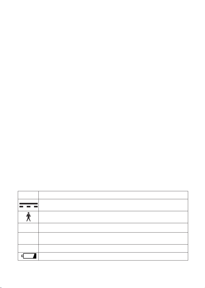
13. Symbols
To comply with international standards for medical equipment, the following symbols are found on
the bath lift’s labels:
10
Symbol Explanation
Only direct current from a small battery is used to power your bath lift. There is NO connection to
mains electricity when in use, so there is no risk of electric shock.
The bath lift is categorised as type B medical equipment and meets international standards for
electrical safety.
The bath lift is sealed to the international standards against the eects of water spray.
The battery is sealed to the international standards against the eects of immersion in water to a
depth of 1 metre/39.37in.
The hand control is protected against long periods of immersion in water under pressure.
This symbol is found on the hand control and means the light represents the battery status.
IP66
IP67
IP68

179mm/7’’ 360mm/14.2’’ 179mm/7’’ 860mm/33.9’’
475mm/18.7’’
676mm/26.6’’
14. Technical data
The bath lift seat is made of glass-lled polypropylene/nylon. The hand control and battery are made
from ABS. The hand control button cover is made of Thermoplastic Elastomer.
The bath lift is in the ocial category of “internally powered equipment” and is not suitable for use in
the presence of ammable anaesthetic mixture with air or nitrous oxide.
The equipment is tested in accordance with:
• BS EN 60601-1: 2006
• BS EN 10535:2006
• The European Council Directive 93/42/EEC relating to Medical Devices
The bath lift complies with the WEEE directive.
DISPOSAL: The plastic, metal parts, packaging materials and suction feet are recyclable but the
Nickel Metal Hydride (NiMH) battery, should be disposed of only by returning it to your supplier, the
manufacturer or an authorised disposal point.
Symbol Explanation
PLEASE READ THE INSTRUCTIONS BEFORE INSTALLATION OR USE.
Do not bin/dispose.
Serial number.
Re-order number.
Maximum load – lifting capacity (person).
Caution! Surface hot to touch.
11

Bath Lift
Lifting capacity (person) 22 stone/140kg/308lbs
Net weight (excluding battery) 9.6kg/21.16lbs
Seat base weight 6kg/13.23lbs
Backrest weight 3.6kg/7.94lbs
Seat height UP 440mm (17.32in)
Seat height DOWN 75mm (2.95in)
Backrest height 690mm (27.17in)
Power input 14.4V dc nominal 7A max
Duty cycle No more than one bath per 15 minutes
Degree of protection IP66
Angle of recline 35°
Hand Control (Battery)
Input 14.4V dc nominal 1.0A
Output 14.4V dc nominal 7A max
Degree of protection IP 68
Battery IP67
Battery Charger
Input 100-240V ac 50-60Hz 1.0A
Output 14.4V dc nominal 1.0A
Operating and charging
Temperatures
Max 40°C (104°F)
Min 0°C (32°F)
Shipping and storage
Weight (packaged) 13kg (28.66lbs)
Shipping volume 0.07m³ (2.48ft³)
Temperatures
Max 40°C (104°F)
Min -10°C (14°F)
Humidity
Max 90% RH
Min 10% RH
Pressure
Max 125kPa (18.4psi)
Min 73kPa (10.7psi)
12
This product is suitable for transport in
pressurised aircraft holds.

13
15. Troubleshooting
Symptom Possible Cause Solution Section
Bath lift does not
move. No sound
from the motor.
• Battery is at. • Charge battery. Section 2
• Battery is not
connected to hand
control.
• Insert battery correctly into both tracks
on hand control cradle and slide all the
way to the end until it clicks.
Section 6
• Not pressing correct
area on hand
control buttons.
• Press arrowhead on either UP or DOWN
buttons. Continue to press.
Section 6
• Faulty electronics in
hand control.
• Contact supplier or authorised service/
repair centre.
n/a
• Battery fault. • Contact supplier or authorised service/
repair centre. Replace battery.
n/a
• Actuator fault. • Contact supplier or authorised service/
repair centre.
n/a
Red light on hand
control is on and
bath lift only
moves up.
• Battery is at or
has not been fully
charged and Stop
Descent™ has been
activated to prevent
the bath lift lowering.
• Charge battery immediately. Section 2
Red light on hand
control is on but
bath lift does not
move.
• Battery is at and has
not been charged for
long period (typically
7-10 days).
• Charge battery immediately.
• Charge battery before use if bath lift has
not been used for long periods (typically
7-10 days).
• Do NOT start bath with RED light on
hand control. Charge immediately.
• Ensure battery is placed on charge as
soon as you nish your bath if FLASHING
GREEN light appears on hand control.
• When bath lift is not in use, leave battery
connected to hand control. Disconnect
only for charging or when moving bath lift.
• It is recommended the battery be charged
after each bath, wherever possible.
• Battery fault. • Contact supplier or authorised service/
repair centre.
n/a

Symptom Possible Cause Solution Section
Bath lift
only moves
intermittently.
• Battery is not fully
charged.
• Charge battery. Section 2
• Excessive user load. • Do not use bath lift if you weigh over
22st/140kg/308lbs.
Section 14
• Bath lift has
encountered
obstruction during
lifting, e.g. integral
bath handles, soap
dish.
• Lower bath lift, pull aps free from
obstruction, then resume lifting
operation.
• Fit side ap protectors to any integral
bath handles.
Section 7
Battery does
not appear to be
charged.
• Power to charger is
not switched on.
• Ensure charger plug is connected to
power socket and switch on. Check for
light indicator on charger box.
Section 2
• Battery is not
connected correctly
to charging cradle.
• Insert battery correctly into both tracks
on charging cradle and slide all the way
to the end until it clicks.
Section 2
• Battery has
discharged before
use.
• Ensure battery is disconnected from
charging cradle when mains socket
is switched o or when charger is
removed from mains socket.
• Charge battery after long periods of
non-use (typically 7-10 days).
Section 2
• Interruption to
mains power
supply/faulty mains
socket.
• Check for charger indicator lights at
alternative power socket.
• Check if other electrical appliances are
working.
n/a
• Charger fault. • Contact supplier or authorised service/
repair centre.
n/a
• Battery fault. • Contact supplier or authorised service/
repair centre.
n/a
Charger is plugged
into power socket
but charger
indicator lights do
not appear.
• Battery is not
connected correctly
to charging cradle.
• Insert battery correctly into both tracks
on charging cradle and slide all the way
to the end until it clicks.
Section 2
• Charger fault. • Contact supplier or authorised service/
repair centre.
n/a
14

15
Symptom Possible Cause Solution Section
No lights appear
on hand control
when buttons are
pressed.
• Battery is not
connected correctly
to hand control.
• Insert battery correctly into both tracks
on hand control and slide all the way to
the end until it clicks.
Section 6
• Faulty electronics in
hand control.
• Contact supplier or authorised service/
repair centre.
n/a
Backrest is not
secure on seat
unit.
• Backrest not
assembled correctly
onto seat unit.
• Ensure actuator end is fully retracted.
• Place backrest face down on seat in
front of rear seat blocks and ensure
hinges locate in both seat unit slots.
• Hold top of backrest and tilt upwards
until it locks into fully reclined position.
Section 5
Suction feet will
not stick to the
bath surface.
• Front suction feet
are located over
rippled surfaces.
• Contact supplier for advice on suitability
of centre sucker xture kit for use with
your bath lift.
Section 4
& section
16
• Base of bath too
narrow - feet not
making contact
with bath surface.
• Seat is too wide for lower contours of
bath. Contact supplier for advice on
suitability of height adapter kit.
Section 16
• Bath surface is
dirty/dusty or
enamel is worn.
• Clean bath surface and underneath
suction feet before installing bath lift.
Section 4
• Suction feet are old
or damaged.
• Contact supplier or authorised service/
repair centre for replacements.
n/a
16
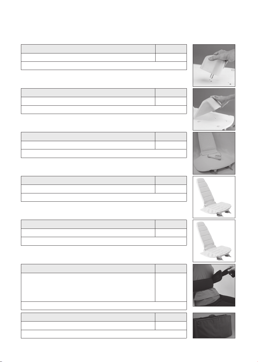
Accessory Part No.
Knee wedge AB249
Supports legs, maintains correct posture or prevents sliding.
Accessory Part No.
Soft cover set (back and seat) AB224
Increases comfort.
Accessory Part No.
Cushioned cover set (back and seat) AB225
Provides even greater comfort.
Accessory Part No.
Thoracic harness (including xture kit) Adult -
AB232
Child -
AB231
Helps maintain upper body posture or prevents slipping.
Accessory Part No.
Carry bag AB250
Protects bath lift while travelling and facilitates transport.
Accessory Part No.
Cushioned cover set paediatric (back and seat) AB226
For use with pommel and knee wedge.
16. Accessories
The bath lift can be supplied with a wide range of optional accessories:
Accessory Part No.
Pommel AB248
Separates legs for maintaining correct posture or improving hygiene access.

17
Accessory Part No.
Pelvic harness Adult -
AB230
Child -
AB229
Helps maintain body posture or prevents slipping
Accessory Part No.
Slide and swivel aid AB247
Facilitates transfer on and o the seat. Must be used with seat cover.
Accessory Part No.
Height adapter set (25mm/1in) AB213
Fits to the suction feet to increase height of bath lift in exceptionally deep baths
Accessory Part No.
Centre sucker xture kit AB228
Attaches front suction feet to middle of base frame in baths with rippled surfaces.
Accessory Part No.
Side ap protector extension kit (non- hooking) AB287
Comprises 1 non-hooking side ap protector and 2 clips. Where a standard
side ap protector cannot be moved further along an integral bath handle to
enable the side ap to rest substantially over it, this kit enables an additional
side ap protector to be attached beyond the end of the bath handle. This
provides a substantial surface area for the side ap to glide smoothly over
the bath handle. Use several kits to attach as many side ap protectors as
required beyond the bath handle.
Accessory Part No.
Side ap protector extension kit AB284
Comprises 1 side ap protector and 2 clips. By attaching one or more side
ap protectors together, a wider side ap protector can be formed over
an integral bath handle. This limits the possibility of movement along the
handle or incorrect positioning. Use several kits to attach as many side ap
protectors as required to t the handle length.
1
2
3
13
9
4
5
8
7
6
10
11
12
24
23
22
21
28
20
19
18
17
16
15
14
27
26
28
18
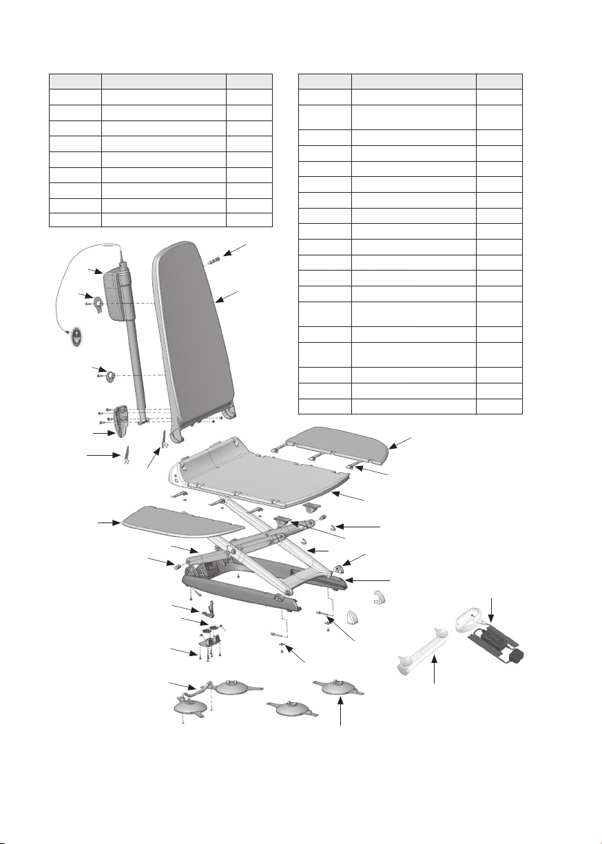
17. Parts List
ITEM No. Description Part no.
1 Actuator Snap Pin AB003
2Backrest AB014
3 Lh Side Flap AB016
4Hinge A167
5Seat with Blocks Fitted AB281
6 Snap Washer AB008
7Slide Block Upper AB007
8 Scissor Outer AB005
9Slide Block Lower AB006
ITEM No. Description Part no.
10 Base Frame AB018
11 Sucker Swivel Pin - Front
and Rear AB019
12 Rectangular Washer AB010
13 Suction Foot (Front) AB002
14 Rear Suction Feet Assembly AB251
15 Cover Lock Levers AB015
16 Actuator Lock Lever AB011
17 Scissor Lock Lever AB009
18 Hinge Pin Back and Front AB001
19 Scissors Inner AB004
20 Rh Side Flap AB017
21 Actuator Clamp AB012
22 Cable Winder AB021
23 Cable Winder with Retainer
Clip AB022
24 Actuator AB020
25 Side Flap Protector (not
shown) AB212
26 Battery A230
27 Smart Charger NiMH CU-3000
28 Seat Unit Blocks with Fittings AB280
® Tunstall and Lifeline are registered trademarks of Tunstall Group Limited.
Mountway Limited reserve the right to alter specications to products or packaging at any time.

Diagram sheet
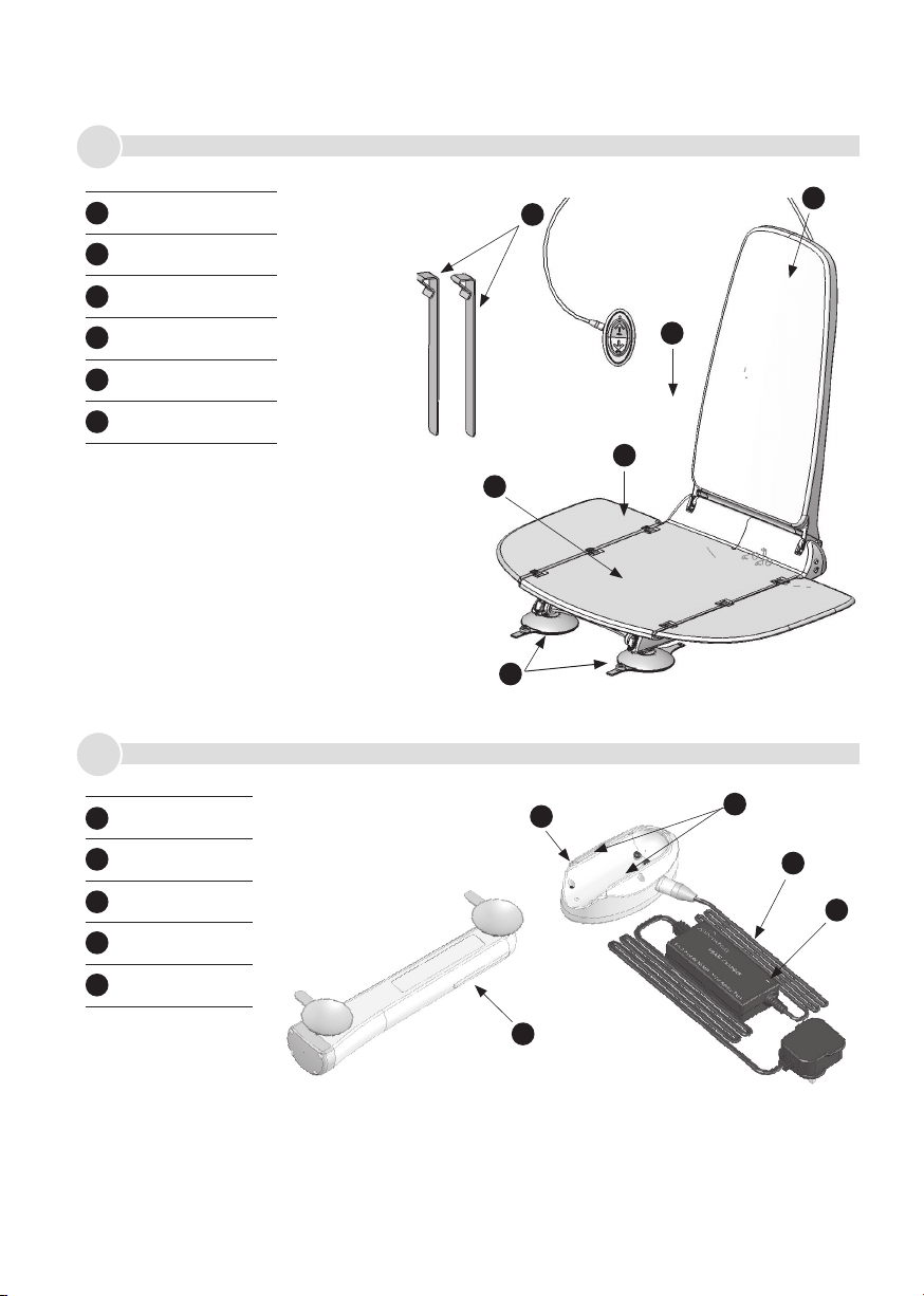
1
Figures
2
D
E
A
B
C
F
AB
C
D
E
Hand control
Side ap
Seat unit
Side ap protectors
Backrest assembly
Front suction feet
A
B
C
D
E
F
Charging cradle
Tracks
Charger
Light indicator
Battery
A
B
C
D
E
Other manuals for Aquila
1
Table of contents
Other Mountway Bathroom Aid manuals


Popular Bathroom Aid manuals by other brands


pba
pba Setrite quick start guide

Lux Products
Lux Products GRIP SAFE GBRG installation instructions

Pressalit Care
Pressalit Care PLUS R7134 Mounting instruction

Graham Field
Graham Field LUMEX 6482R-2 Assembly & operation instructions

lopital
lopital Nemo Instructions for use

Hillsdale Furniture
Hillsdale Furniture 51028 quick start guide