pba Setrite User manual

Pratt Burnerd America
Setrite Self Centering
Scroll Chucks
5" (125mm) - 15" (400mm)
Important: R ad this manual b for using this product:
The Setrite chuck is a durable, steel bodied self centering chuck with a concentricity adjustment feature built
into the body. The front body can be re-aligned in relation to the machine spindle using the various adjusting
screws to the rear of the chucks periphery, workpieces can be trued to within a repeat concentricity of
0.013mm or for optimum accuracy (0.005mm) each component can be trued individually. All components of
the chucks are manufactured from steel, with the scrolls being manufactured in an exceptionally tough alloy
steel and are hardened and ground for accuracy and durability.
Pratt Burn rd Am rica, 3977 Emerald Dr., Kalamazoo, MI 49001
Phone 800-253-0820, Fax No. 269-384-3201 Web Page www.prattburnerd.com e-mail info@prattburnerd. com
1

For ensuring the safe and correct use of this product, please read and pay attention to all the instructions
and keep this manual so that it can be retrieved whenever needed.
1. Saf ty Al rt Symbols
2. Qualifi d Op rators
Pratt Burnerd clamping equipment may be set up,
operated and maintained by those only who are
trained to do so. Persons handling clamping
equipment who do not possess the necessary
training run the risk of potential injury from the
clamping motion and the forces generated.
3. Maximum
P rmitt d Sp d
The maximum permitted speed may only be run at
maximum permitted actuation force and using a
perfectly operating chuck. For maximum permitted
speed ratings see page 3.
4. Exc ding Th
P rmitt d Sp d
The centrifugal forces caused by excessive
rotational speeds may result in individual parts of the
clamping device becoming detached or the work
piece being ejected, with the potential to
cause harm to those in the close vicinity,
considerable damage to the machine and the chuck
itself. The maximum speed and the operating
force/pressures are embossed on the body and may
not be exceeded for the reasons mentioned above.
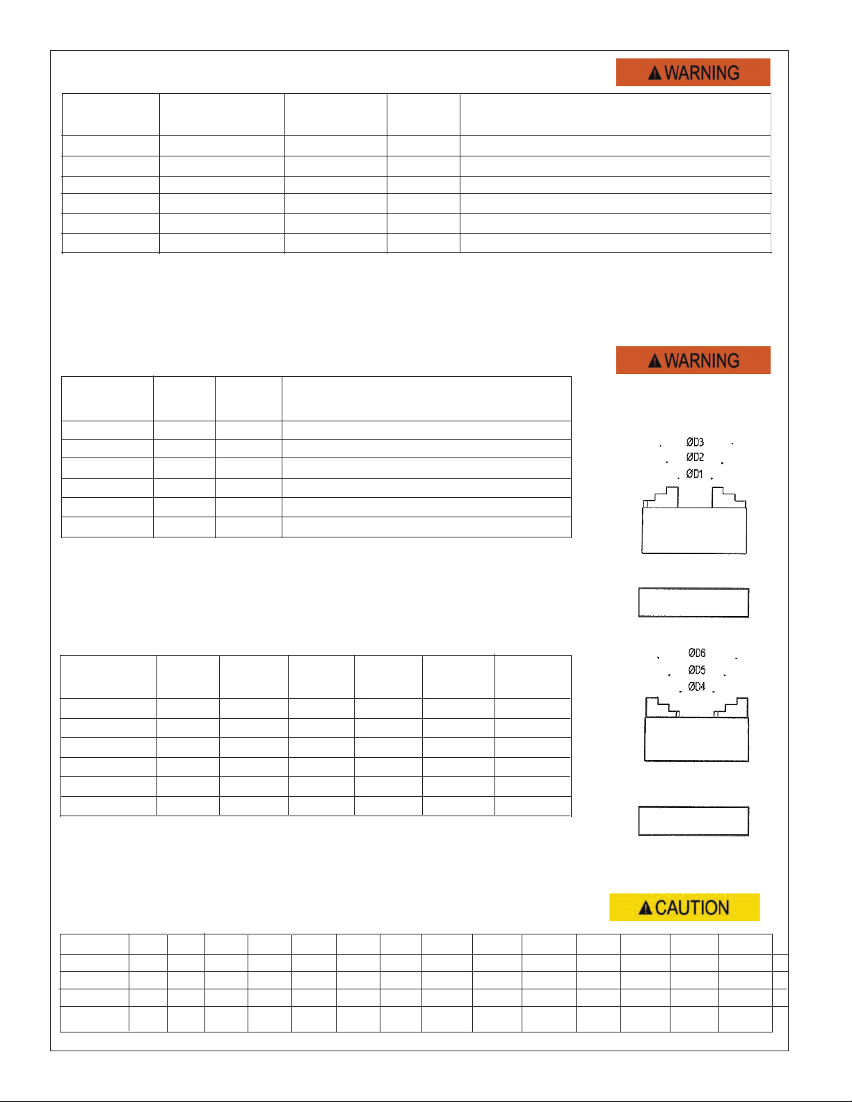
5. Clamping Rang
The maximum clamping range may not be
exceeded, the lack of sufficient engagement
between the clamping jaw and the component part
could cause a negative effect on machining, work
piece ejection or injury to the operator.
For clamping ranges see page 4.
To check the chucking force, it is recommended
using the Pratt Burnerd Radio Frequency Grip
meter. For optimum performance the clamping
force should be checked at regular intervals, the
intervals are dependent on the application, for
more information contact Pratt Burnerd.
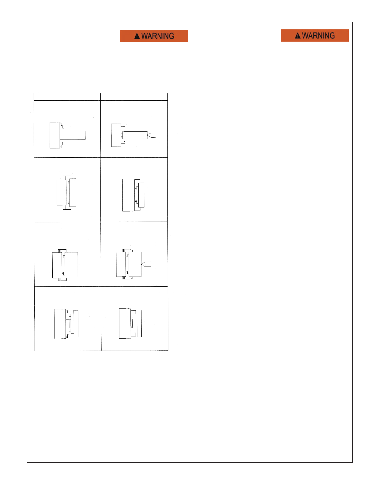
6. Mounting
Clean any excess protective grease from the
chuck and inspect for any damage which may
have occurred in transit. Before mounting the
chuck ensure the machine spindle is running
true by checking the chuck locating faces both
radial and axial directions using a dial indicator
as shown in figure 1. The maximum error should
not exceed 0.005mm full indicator movement
(FIM). Also check the mounting faces are clean
and undamaged. If the chuck is supplied with a
separate mounting adaptor, this should match
the machine spindle and should be secured to it
using the fasteners provided. For torque values
see page 3.
Check the chuck mounting spigot and face for
true running (Fig 2).
The adaptor should run within 0.01mm FIM on
the Face and 0.02mm on the diameter. Wipe
the chuck location faces clean and mount the
chuck to the spindle and adaptor using screws
provided. It is good practice to check the
chuck’s outside diameter and face for the true
running (Fig 3). The chuck may be assessed for
gripping accuracy (Fig 3) by using an accurate
test bar gripped in the chuck and the readings
compared with the particular chucks accuracy
standard.
Figure 1 Figure 2 Figure 3
2

7. Op rating
In order to ensure safe clamping of the work
piece to withstand the machining forces occurring
and prevent injury, the correct loading practices
below should be adhered to:
Wrong Right
Work piece projected
length too great relative
to chuck size.
Support Workpiece
between centers.
Chucking Diameter too
great.
Use a larger chuck.
Chucking diameter too
small.
Chuck using greatest
possible chucking
diameter.
Workpiece too heavy
and chucking step too
short.
Support between
centers and extend
chucking step.
The illustrated examples do not cover all the
possible dangerous situations.
It is the responsibility of the user to recognize
possible sources of danger and to adopt the
necessary measures. Despite all precautionary
measures, an element of risk
can not be excluded.
8. Maint nanc
The reliability of the clamping equipment can only be
ensured if the maintenance guidelines below are strictly
observed. Failure to observe these instructions will result in
loss of grip and could cause an accident.
All chucks should be checked regularly for wear, cracks
and accident damage, the following cause breakages
and should be avoided:
- Do not extend the crosspiece of the chuck key
- Do not use a power wrench to open & close
the chuck
- Do not use a badly fitting operating key
- Do not use the pinion socket to remove the chuck
from the spindle.
- Do not leave the key in the chuck when the lathe is
started.
- Do not start the lathe until all is clear. Collision
between chuck and lathe will almost certainly
damage both.
- Do not use the chuck where as the work piece
diameter is too large resulting in the jaws projecting
beyond the chuck body. Use the jaws in
the correct position. Do not attempt to insert chuck
jaws into the wrong jaw way. The jaws and jaw ways
are numbered correspondingly.
- Do not tamper with the chuck. If inaccuracy is
found, check the spindle nose or adaptor plate
for true running and make sure there is no dirt of
foreign matter between the mounting faces.
- If in doubt, do not use the chuck, contact Pratt
Burnerd
Lubricate the chuck at regular intervals using
Pratt Burnerd chuck lubricant PB160Z, Refer to
material data sheet for all information referring to
PB160Z. Do not use any other brand of lubricant.
To obtain maximum benefit, the chuck parts
should be cleaned thoroughly with a suitable
cleaning fluid before applying the lubricant with a
clean brush.
If spares are fitted to the chuck, ensure these are
supplied by Pratt Burnerd, if screws are loosened
or replaced, defective fastening or replacement
may lead to a damage of the machine or injury to
the operator. The torque table below should be
used when retightening any fasteners Ensure that the
chuck has been tested before reusing.
Use the Pratt Burnerd Radio Frequency Gripmeter to
check the static and dynamic grip.
Pratt Burnerd International will advise on any problem
concerning maintenance.
1
3

Chuck Siz Max Input Total Forc 3 Jaw Approx W ight 6 Jaw Approx W ight
in (mm) Torqu lbs/f (Nm) lbs/f (KN) Maximum 3 Jaw Kg Maximum 3 Jaw Kg
4.92" (125) 40 (52) 5,400 (24.1) 5000 6 3600 7
6.3" (160) 55 (75) 7,500 (33.4) 4900 12 3500 12
7.87" (200) 85 (115) 10,500 (46.8) 4200 21 3000 22
9.89" (250) 115 (156) 12,500 (55.9) 3300 32 2400 35
12.4" (315) 140 (203) 15,000 (66.9) 2300 51 2000 53
15.74" (400) 140 (203) 16,500 (73.5) 2000 66 1500 93
9 T chnical Information
10. Clamping Rang s 1 Pi c Jaws
Chuck siz D1 D2 D3 D4 D5 D6
(mm)
125 1.5-32 28-78 70-120 _ 38-84 78-124
160 1.5-56 42-98 84-152 _ 48-106 90-160
200 2-76 56-126 115-186 _ 54-128 114-200
250 3-114 60-168 148-250 _ 64-162 115-250
315 6-120 70-184 184-298 _ 76-190 190-304
400 10-187 90-268 223-400 _ 92-270 224-406
Chuck siz D1 D2 D3 D4 D5 D6
(mm)
125 1.5-48 32-80 72-118 5-51 48-94 90-136
160 1.5-62 42-102 98-158 10-70 48-108 108-168
200 2.5-68 50-116 106-172 16-82 64-130 122-188
250 4-106 66-164 124-226 16-120 84-186 146-248
315 6-126 70-190 146-266 18-138 98-218 178-298
400 8-168 110-270 178-338 20-180 106-266 176-336
2 Pi c Jaws
10. Tight ning Torqu Ranges (FT-LBS)
Scr w M2 M3 M4 M5 M6 M8 M10 M12 M14 M16 M18 M20 M24 M30
Skt Head Cap
<1.0 1-2 1-5 5-10 10-20 20-30 40-60 40-60 80-100 80-100 80-100 80-100 80-100 100-120
Skt C’sunk
_1-2 1-5 5-10 10-20 20-30 40-60 40-60 _80-100 _80-100 80-100 _
Button Head
_1-2 1-5 5-10 10-20 20-30 40-60 40-60 _
_____
Skt Set Shol. - - - 5-10 10-20 20-30 40-60 40-60
_
80-100 _80-100 80-100
_
Inside Jaws
Outside Jaws
4

PBA PBI A B C F G H I J K L
Chuck Chuck Chuck Size Hard To Base Pinion Scroll Chuck Adjusting Hardened Pinion Chuck Locking Soft To
Model No. Model No. Style Jaw Set Jaw Set Gear Gear Mounting Screw Pin Pin Wrench Screw Jaws Each
Bolts Size
0515400 9219-01351 5" 3 Jaw 8210-13602 O.D. 8210-13603 I.D. 2210-13350 8210-13330 1/4-20x3.0" DGO.375UNF.750 NR 2210-13356 2210-13395 NR 8210-13606*
0516400 9219-01356 5" 6 Jaw 8260-13602 O.D. 8260-13603 I. D. 2210-13350 8210-13330 1/4-20x3.0" DGO.375UNF.750 NR 2210-13356 2210-13395 NR 8260-13606*
0625300 9219-01360 6'' 3 Jaw 8210-17608 8210-17607 2210-17350 8210-17330 1/4-20x3.0" CPO.375UNF1.00 2219-00364 2210-13356 2210-17395 NR 2210-17609
0626300 9219-01365 6'' 6 Jaw 8260-17608 8260-17607 2210-17350 8210-17330 1/4-20x3.0" CPO.375UNF1.00 2219-00364 2210-13356 2210-17395 NR 2210-17609OP
0825300 9219-01370 8'' 3 Jaw 8210-20608 8210-20607 2219-00372 8210-20330 3/8-16x3.5" CPO.375UNF1.00 2219-00364 2310-20356 2218-20208 M10x10 2210-20609
0826300 9219-01375 8'' 6 Jaw 8260-20608 8260-20607 2219-00372 8210-20330 3/8-16x3.5" CPO.375UNF1.00 2219-00364 2310-20356 2218-20208 M10x10 2210-20609OP
1025300 9219-01380 10'' 3 Jaw 8210-25608 8210-25607 2210-25350 8219-01382 7/16-14x3.25" CPO.375UNF1.00 2219-00383 2310-20356 2218-25208 M10x10 2210-25609
1026300 9219-01385 10'' 6 Jaw 8260-25608 8260-25607 2210-25350 8219-01382 7/16-14x3.25" CPO.375UNF1.00 2219-00383 2310-20356 2218-25208 M10x10 2210-25609OP
1225300 9219-01390 12'' 3 Jaw 8210-32608 8210-32607 2210-32350 8210-32330 1/2-13x3.25" CPO.375UNF1.00 2219-00383 2310-20356 2218-32208 M10x10 2210-32609
1226300 9219-01395 12'' 6 Jaw 8260-32608 8260-32607 2210-32350 8210-32330 1/2-13x3.25" CPO.375UNF1.00 2219-00383 2310-20356 2218-32208 M10x10 2210-32609OP
1525300 9219-01400 15'' 3 Jaw 8210-40608 8210-40607 8270-40350 8219-01403 5/8-11x3.75" CPO.625UNF1.00 2219-00383 2310-20356 8271-40385 M10x10 2210-38609
1526300 9219-01405 15'' 6 Jaw 8260-40608 8260-40607 8270-40350 8219-01403 5/8-11x3.75" CPO.625UNF1.00 2219-00383 2310-20356 8271-40385 M10x10 2210-28609OP
Note: 5" Chuck use Solid I.D and O.D Jaws
*5" Chuck use soft solid jaws and are sold in sets
When Ordering spares please have the Chuck Model number available located on the Chuck face.
Contact Pratt Burnerd America, 3977 Emerald Dr., Kalamazoo, MI 49001
Phone 800-253-0820, Fax No. 269-384-3201 Web Page www.prattburnerd.com e-mail info@prattburnerd. com
5
Fig 2

14. Th S trit F atur
Pratt Burnerd power chucks are manufactured to the highest tolerances in accordance with all
accepted international standards specifications. Indeed, all sizes of Pratt Burnerd power chucks will
repeat to within 0.025mm however the absolute accuracy with which a chuck can hold and rotate a
component depends in part on the interface between the chuck and spindle nose.
The Pratt Burnerd Setrite feature has been designed to compensate for any inaccuracy which may be
introduced in mounting the chuck and spindle nose adaptor.
At the rear of the chuck body periphery there are three small cap screws (six on chucks of Ø380mm
and above) which control float between the chuck body components or between the chuck and
spindle nose adaptor.
The Setrite feature is simple to use, for direct mounting chucks, the chuck should be offered up to the
spindle nose in accordance with the instructions on page 2, ensuring that all mating surfaces are
thoroughly cleaned. The through mounting bolts should be made hand tight. Check the run out on the
chuck periphery using a suitably position dial indicator. Adjustment of the Setrite screws will bring the
chuck true on the spindle nose. The through mounting bolts should then be fully tightened.
For chucks with separate adaptors, first mount the adaptor to the spindle nose observing all the usual
precautions detailed in the mounting section of this manual. The mounting bolts should be fully
tightened. Offer the chuck up to the adaptor, insert the through mounting bolts and tighten them by
hand. Adjust the Setrite screws to obtain optimum accuracy and fully tighten the mounting bolts as before.
Once set, the Setrite screws will require no further adjustment unless the chuck is removed from the
spindle, when the above procedure should be repeated to re-true the chuck.
15. Fitting Camstuds to Camlock Mount Chucks
Chucks for direct mounting to lathes with camlock mounts are now delivered with the camlock studs
packed separately within the chuck case. This reduces the risk of damage in transit to both chucks
and studs. The following notes are offered guidance in assembling the studs to the chuck.
Screw each camstud into the mounting holes provided until the datum line is as close as possible to
the rear face without being below the surface and the screw head cutout in the line with the locking
screw hole.
Ensure that the chuck and spindle nose tapers are clean and offer the chuck up to the spindle. When
in position, tighten each of the spindle cams in turn, ensuring the datum line on each cam is between
the arrows on the spindle nose. If any don not tighten within the limits, remove the chuck and adjust
the camlock studs as required. When all cams lock within the marked limits, remove the chuck and
insert the locking screws beside each cam lock stud. Remount the chuck.
Remember once a chuck has been adjusted to a spindle nose, inscribe a reference mark so that each
time it is removed from the machine, it may be replaced in the same position. If the chuck is mounted
on a different machine from that which it has been adjusted, the above procedure should be repeated.
6

15. Insid or Outsid Jaws
The most common misunderstanding in the chucking world is the terminology of inside and outside
jaws for self centering chucks, a point which appears to have caused confusion since chucking was
introduced and still does.
OUTSIDE jaws are designed only to grip OUTSIDE components, usually of larger diameters.
INSIDE jaws are designed to grip the INSIDE diameter of a ring of cylinder but will also grip the out
side diameter of bar material which is, by far, the most common application and complicates the
terminology.
To simplify:
16. Fitting Spar Jaws
Spare jaws are manufactured to allow for some
degree of wear which may have taken place in the
chuck, therefore are left slightly oversized on the
width X of the jaw and undersize on the width Y of
the tenon and it is possible that a minor degree of
fitting may be required to obtain the correct fit of the
jaw. When fitting scroll jaws, the width of the tenon
slot Y should be ground to size by removing metal
from one side of each tenon slot. Always
grind the corresponding side of each slot in order to
preserve the accuracy of the height of the steeped
platform faces. Although ground on the gripping
faces as accurately as possible, spare jaws will not
provide the accuracy of the original set which were
ground in the chuck. To obtain original standards of
accuracy, the gripping faces and platform steps must
be ground in the chuck. It is necessary to remove all
backlash between the jaw teeth and scroll head.
7

Pratt Burn rd Am rica.
3977 Emerald Dr. Kalamazoo, MI.
(800) 253-0820 FAX (269) 384-3201
MATERIAL SAFETY DATA SHEET
CHEMTREC (800) 424-9300 (24HR)
PRODUCT TRADE NAME: Pratt Burn rd Chuck Lubricant PRODUCT CODE: PB16OZ
EFFECTIVE DATE: JANUARY 1, 2001 PB10LB
MANUFACTURED BY: HUSK-ITT CorporationPAGE 1 OF 2
THIS MATERIAL SAFETY DATA SHEET CONTAINS ENVIRONMENTAL, HEALTH AND TOXICOLOGY INFORMATION
FOR YOUR EMPLOYEES. PLEASE MAKE SURE THIS INFORMATION IS GIVEN TO THEM. IT ALSO CONTAINS
INFORMATION TO HELP YOU MEET COMMUNITY RIGHT-TO-KNOW/EMERGENCY RESPONSE REPORTING RE-
QUIREMENTS UNDER SARA TITLE 111 AND MANY OTHER LAWS. IF YOU RESELL THIS PRODUCT, THIS MSDS
MUST BE GIVEN TO THE BUYER OR THE INFORMATION INCORPORATED IN YOUR MSDS.
DOT HAZARDOUS CLASSIFICATION: NOT REGULATED GREASE OR OIL - N.O.S.
NFPA HEALTH HAZARD: 1 FLAMMABILITY: 1 REACTIVITY: 1 PERSONAL PROTECTION: B
SECTION 01 - HAZARDOUS INGREDIENTS
IF PRESENT, IARL, NTP AND OSHA CARCINOGENS AND CHEMICALS SUBJECT TO THE REPORTING
REQUIREMENTS OF SARA TITLE 111, SECTION 313 ARE IDENTIFIED IN THIS SECTION.
CAS NUMBE TLV PEL %
(NON HAZARDOUS) COMPONENTS
PETROLEUM OILS 64741-96-4 N/E N/E 60-70
64742-62-7 N/E N/E 60-70
LITHIUM HYDROXYSTEARATE 7620-77-1 N/E N/E 5-10
MOLYBDENUM DISULFIDE 1317-33-5 N/E N/E 15-25
PROPRIETARY COMPONENTS N.J.T.S.R.N.
80100362-5009P < 1.0
SECTION 02-PHYSICAL DATA
WATER SOLUBILITY. . . . . NIL BOILING POINT, F °. . . . . . . . . . . . N/A
SP, GRAVITY. . . . . . . . . . 1.02 MELTING POINT, F°. . . . . . . . . . . . N/A
APPEARANCE & COLOR . . DARK,PASTE LIKE VOLATILE BY VOLUME, %. . . . . . . NONE
ODOR . . . . . . . . . . . . . . . NONE VAPOR PRESSURE . . . . . . . . . . . . . N/A
EVAPORATION RATE . . . . N/A VAPOR DENSITY . . . . . . . . . . . . . . N/A
SECTION 03-FIRE AND EXPLOSION HAZARDS
FLASH POINT:(ASTM D92) C.O.C. 450°F UPPER FLAMMABLE LIMIT: N/D LOWER FLAMMABLE LIMIT: N/D
EXTINGUISHING MEDIA: DRY CHEMICAL, WATER FOG, FOAM, CARBON DIOXIDE, SAND/EARTH
SPECIAL FIRE FIGHTING PROCEDURES: TREAT AS OIL FIRE: USE SELF-CONTAINED BREATHING
APPARATUS. UNUSUAL FIRE & EXPLOSIVE HAZARDS: NONE
8

MSDS - Pag 2 Pratt Burn rd Am rica PART No. PB16OZ
SECTION 04-ENVIRONMENTAL AND DISPOSAL INFORMATION
ACTION TO BE TAKEN FOR SPILL/LEAKS: Stop flow, scrape, wipe, mop up, or absorb with
diatomaceous earth or other inert material. Store in appropriate container for disposal.
DISPOSAL METHOD: Disposal should be in compliance with federal, state, and local laws.
SECTION 05-HEALTH HAZARD DATA
CARCINOGENS: No carcinogens present
ROUTE OF ENTRY: Ingestion
EFFECTS OF OVEREXPOSURE: May cause irritation to eyes and skin on sensitive individuals.
EMERGENCY FIRST AID PROCEDURES:
EYES: Flush with water for at least 15 minutes.
SKIN: Wash with soap and water. See physician if irritation persists.
INHALATION: Remove to fresh air. See physician if irritation persists.
ORAL: Call a physician. Do not induce vomiting. Keep warm.
ADDITIONAL: Prolonged or repeated contact may produce mild skin irritation and inflammation.
Personnel with pre-existing skin disorder should avoid contact.
SECTION 06-REACTIVITY DATA
STABILITY: Stable
INCOMPATIBILITY: Strong oxidizing agents, welding.
POLYMERIZATION: Will not occur
THERMAL DECOMPOSITION: Carbon Monoxide, Carbon Dioxide, Metallic and Sulfur Compounds
CONDITIONS TO AVOID: Do not heat above flash point.
SECTION 07-SPECIAL PROTECTION INFORMATION
RESPIRATORY PROTECTION: Normally not needed.
GLOVES PROTECTION: Neoprene or nitrile rubber gloves recommended.
EYE PROTECTION: Approved safety glasses or goggles
OTHER PROTECTION: Chemically resistant boots and apron recommended.
WORK/HYGIENIC PRACTICES: Use standard methods
SECTION 08-SPECIAL PRECAUTIONS AND ADDITIONAL INFORMATION
Avoid storage near open flame or other sources of ignition. Spills may cause slippery floors. Proper
footwear required. Remove contaminated clothing and launder before reuse. Wash hands with soap and water
before eating, drinking or smoking. Discard contaminated leather gloves and shoes.
The above information is based on the data of which we are aware and believed to be correct as of the date
hereof. Since the information contained herein may be applied under conditions beyond our control and with
which we may be unfamiliar and since data made available subsequent to the date hereof may suggest
modification of the information, we do not assume any responsibility for the results of its use. This information is
furnished upon condition that the person receiving it shall make his/her own determination of the suitability of the
material for his/her particular purpose.
May be used to comply with OSHA'S Hazard Communication Standard 29 CFR 1910.1200. Standard must be consulted for specific requirements.
N/D - N t Determined N/A - N t applicable < - Less Than > - Greater Than
MSDS214.DOC
9
Table of contents
Other pba Bathroom Aid manuals
Popular Bathroom Aid manuals by other brands

Reval
Reval Soflex instruction manual

aidapt
aidapt Viscount Raised Toilet Seat Usage and maintenance instructions

CareCo
CareCo Soho BA06044 Usage and maintenance instructions

Santec
Santec 3966CI10 quick start guide

The Splash Lab
The Splash Lab TSL.GR45.36 Installation & maintenance

Gordon Ellis & CO
Gordon Ellis & CO Big John Instructions for use

Helvex
Helvex Access ACC-105 installation guide

Graham Field
Graham Field LUMEX 7927KD-1 quick start guide

Pressalit Care
Pressalit Care PLUS R7404 Mounting instruction

Gordon Ellis & CO
Gordon Ellis & CO SERENITY Instructions for use

Herdegen
Herdegen Contact Plus quick start guide

HERO
HERO S13965 user manual