Mountz Titan 100i User manual

0
1
0
1
TITAN
100i
250i
75F
150F
300F
600F

6 - 12
US
13 - 20
ES

MANUFACTURER’S
DECLARATION
Our torque wrenches meet the
requirements of ISO Standards
6789, Type II: Signal Torque
Wrenches; Class A: Wrench
with adjustable scale.
SERVICE-HOTLINE
408-292-2214
Service
Calibration
Repairs

a
b
c
d
e
f
0
1
0
1
4
TITAN 600F

5
0
1
1
0
1
+10%100%
2
0
1
100%
34
0
1
1
3
2
180
5
6
7 8 9
10 11

6
TITAN
These operating instruc-
tions contain important
information for the
smooth operation of
your torque wrench!
CONTENTS
Manufacturer’s
declaration . . . . . . . . . . . 3
Safety instructions . . . . . 6
Range of application . . . 7
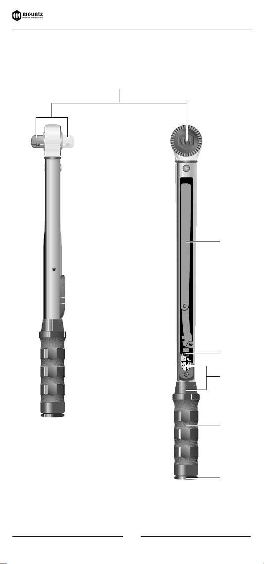
Functional units . . . . . . . 7
Setting the torque. . . . . . . 7
Controlled tightening
of screw. . . . . . . . . . . . . . 8
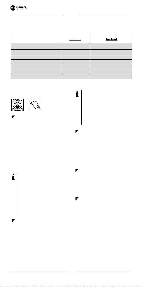
Divisions . . . . . . . . . . . . . 9
Testing & servicing. . . . . 9
Conservation. . . . . . . . . 10
Accessories &
spare parts . . . . . . . . . . 10
Measures & units . . . . . 10
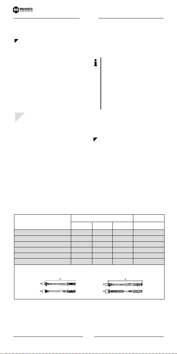
Measurements &
Weights . . . . . . . . . . . . . 10
Warranty . . . . . . . . . . . . 11
Torque conversion
factors . . . . . . . . . . . . . . 12
SAFETY INSTRUCTIONS
Your torque wrench is a
precision tool. Despite its
robust design the torque
wrench should be used
like measuring and test
equipment.
Do not use your torque
wrench as a striking tool
as it might be destroyed
in the process.
Before using your
torque wrench
please
ensure that it is calibrated
according to specifica-
tions. A test certificate in
compliance with ISO 6789
is enclosed with all new
torque wrench
models.
Please attach only stan-
dard sockets and acces-
sories to your
torque
wrench.
Do not use worn
or defective accessories
and, if at all possible, do
not use reduction
adapters.
In order to avoid the
danger of slipping always
attach your
torque wrench
onto the bolted joint at a
right angle.
Please do not exceed the
set torque value. Your
torque wrench
automati-
cally triggers when set
torque is reached. A click
signal is heard and felt.
After this relieve strain as
quickly as possible.
Your
torque wrench
must not be used to loosen
bolted joints.
Please do not exceed the
permitted range of torque
on your
torque wrench
.
Excessive tightening might
cause material rupture in
your
torque wrench
!

TITAN
RANGE OF
APPLICATION
Your
torque wrench
is only suitable for the
specified purpose.
Your
torque wrench
is
designed exclusively for
the controlled tightening
of bolts.
Any other additional
use of your
torque wrench
is considered an abuse of
the specified purpose.
The company does not
accept liability for dam-
age incurred in this way,
nor will it, in this case,
accept any other claims
under the guarantee.
FUNCTIONAL UNITS
aRatchet drive with
push-through, or inter-
changeable square
bIntermediate lever
cSpring
dScale + graduated collar
lbf•in / lbf•ft and N•m
eHandle
fLocking button
SETTING THE TORQUE
Pictures 1– 4
Pull out the locking
button on the end of the
handle.
Turn the handle in a
clockwise or anticlockwise
direction to set the torque.
Set the torque value to
5-10 % above the desired
value.
The set torque is read-
able on the scale or on
the scale connected to
the graduated collar*.
According to the
model, the scale or
graduated collar*
shows different pit-
ches. A table with the
respective divisions
can be found in the
section “DIVISIONS”.
Now set the torque
value, previously set 5-10%
above the desired value,
back to the true value.
Please pay attention to
the unit of measure-
ment on the scale
applicable to you
(
lbf•in / lbf•ft or N•m
).
Push the locking
button back into the cavity.
*According to the model
!
7
1
2
3
4
TITAN

CONTROLLED
TIGHTENING OF SCREW
Pictures 5– 11
Your torque wrench is
suitable for controlled
right hand tightening and
left-handed-way.
The tightening direc-
tion is indicated by
an arrow on the
measuring tool.
According to your
model, the direction
is reversed as follows:
TITAN 100i-300F with
interchangeable square.
Take out the square on
the mushroom head, turn
the torque wrench and
replace the square.
TITAN 600F with
push-through square.
Push the square through
the ratchet.
Attach possible acces-
sories and/or matching
socket for your screw
connection.
Place your
torque
wrench
together with the
socket onto the thread
joint at a right angle.
Attention!
To avoid damage or
slipping always use
the extension that
takes the
torque
wrench
as closely as
possible to the thread
joint.
Operate your torque
wrench exclusively by the
handle using 1 or 2 hands,
at the same time pulling in
the direction of the arrow
until it releases (click sig-
nal).
At this point the set
torque will have been
achieved.
The releasing signal is
clearly heard and felt.
Do not keep on tight-
ening the bolt after
the releasing signal!
After the automatic
release your
torque
wrench
is immediately
ready for further action.
Attention!
The torque transmis-
sion is dependent on
the lever arm. The use
of the tool outside the
handle area, or the
use of extension tubes
or special additional
tools, has a negative
effect on the torque
values. Always apply
the force on the cen-
tre of the handle do
not use extensions.
6
7
8
8
5
9
10
TITAN

TESTING & SERVICING
The manufacturer guar-
antees a torque wrench
accuracy of +/- 4% to the
scale value in question at a
stress cycle of max. 5000.
It is therefore necessary
that you test your torque
wrench at least every 5000
stress cycles on a traceable
calibrated testing device.
For the testing of your
tool we recommend
torque analyzer
testing equipment.
For information
contact Mountz Inc.
or simply call our
Service-Hotline.
Your torque wrench has
to be calibrated at least
once a year. Re-adjust-
ments should only be
carried out either by autho-
rised personnel, accredited
calibration labs or the
manufacturer.
For calibration, re-
adjustment or repairs
we recommend the
service department
of Mountz Inc., the
in-house calibration
lab.
Before a longer period
of non-utilisation the
compression spring of
your
torque wrench
needs
to be released. Turn the
torque back to the small-
est value on the scale.
Protect your torque
wrench from dust, dirt and
sand by placing it back in
the box after use and store
it in a dry, clean place.
Clean your torque
wrench on the outside
with a dry, clean cloth.
Do not use cleaning spirit
or any other chemical
solvents as these interfere
with the permanent lubri-
cation of the mechanism.
9
DIVISIONS
TORQUE WRENCH
Graduation Graduation
- collar
# !
TITAN
100i 1/4“ 20-100 lbf•in 5 lbf•in no collar
250i 3/8“ 50-250 lbf•in 10 lbf•in 1 lbf•in
75F 3/8“ 10-75 lbf•ft 2.5 lbf•ft 0.25 lbf•ft
150F 1/2“ 30-150 lbf•ft 5 lbf•ft 0.5 lbf•ft
300F 1/2“ 60-300 lbf•ft 10 lbf•ft 1 lbf•ft
600F 3/4“ 120-600 lbf•ft 10 lbf•ft 1 lbf•ft
TITAN

Weights in kg
0.5
0.6
0.9
1.1
1.6
5.2
10
MEASUREMENTS & WEIGHTS
TITAN
# !
TITAN 600FTITAN 100i - 300F
CONSERVATION
Packaging materials as
well as the
torque wrench
are made of recyclable
materials and are to be
disposed of at the appro-
priate recycling centers.
ACCESSORIES &
SPARE PARTS
Extensions, sockets
screwdriver, screwdriver
bits, rotation angle meas-
uring equipment and
special tools for a variety
of applications.
Use only original acces-
sories and spare parts.
Information about the
range of available acces-
sories or spare parts for
your
torque wrench
are
listed on the Mountz web-
site www.etorque.com.
When placing a spare
part order always
state the serial num-
ber and year or manu-
facture of your
torque
wrench
model. (For
details refer to test
certificate).
MEASURES & UNITS
For details about meas-
ures, torque, conversion
tables and stud torque
units please refer to
manufacturer’s catalogue.
11
10
TITAN
Measurements in mm
abc
100i 1/4“ 20-100 lbf•in 33 43 307.0
250i 3/8“ 50-250 lbf•in 33 43 350.0
75F 3/8“ 10-75 lbf•ft 33 43 394.0
150F 1/2“ 30-150 lbf•ft 33 43 485.0
300F 1/2“ 60-300 lbf•ft 33 46 664.5
600F 3/4“ 120-600 lbf•ft 33 69 1,200.0

WARRANTY
Every Mountz tool is
thoroughly checked and
tested before shipment.
Should defects due to
faulty materials and/or
workmanship develop
within one (1) year from
the date of sale, the tool
will be repaired and put in
workable condition or
replaced free of charge (at
Mountz option), if returned
to Mountz, Inc.
This warranty is not
valid if a product has been
misused, tampered or
abused. Also, Mountz war-
ranty does not cover rental
or leased products. Any
questions concerning war-
ranty should be directed to
Mountz Customer Service.
11
TITAN

12
TORQUE CONVERSION FACTORS
Units to be converted Corresponding unit
= mN•m=cN
•m= N•m = ozf•in = lbf•in = lbf•ft = gf•cm = kgf•cm (kp•cm) = kgf•m (kp•m)
1 mN•m 1 0.1 0.001 0.142 0.009 0.0007 10.2 0.01 0.0001
1 cN•m 10 1 0.01 1.416 0.088 0.007 102 0.102 0.001
1 N•m 1000 100 1 141.6 8.851 0.738 10197 10.2 0.102
1 ozf•in 7.062 0.706 0.007 1 0.0625 0.005 72 0.072 0.0007
1 lbf•in 113 11.3 0.113 16 1 0.083 1152.1 1.152 0.0115
1 lbf•ft 1356 135.6 1.356 192 12 1 13826 13.83 0.138
1 gf•cm 0.098 0.01 0.0001 0.014 0.0009 0.00007 1 0.001 0.00001
1 kgf•cm (kp•cm) 98.07 9.807 0.098 13.89 0.868 0.072 1000 1 0.01
1 kgf•m (kp•m) 9807 980.7 9.807 1389 86.8 7.233 100000 100 1
Conversion-formula: Units to be converted x Factor = Corresponding unit
Example:Convert 5 lbf•ft into cN•m
Solution: 5 x 135.6 = 678 cN•m
TITAN

13
DECLARACION DEL
FABRICANTE
Nuestras llaves dinamométricas
cumplen con los requerimientos de
las Normas ISO 6789, tipo II: Llaves
Dinamométricas de señal. Clase A:
Llave con escala ajustable.
SERVICIO HOTLINE
408-292-2214
Servicio
Calibración
Reparaciones
TITAN

14
Estas instrucciones de uso
contienen información
importante para el correc-
to funcionamiento de llave
dinamométrica!
CONTENIDO
Declaración del
fabricante . . . . . . . . . . . 13
Instrucciones de
seguridad . . . . . . . . . . . 14
Rango de aplicación. . . 15
Unidades funcionales . 15
Ajustar el par . . . . . . . . 15
Apriete controlado
de un tornillo . . . . . . . . 16
Divisiones . . . . . . . . . . . 17
Comprobación
y servicio . . . . . . . . . . . 17
Conservación . . . . . . . . 18
Accesorios y repuestos 18
Medidas y unidades. . . 18
Medidas y pesos . . . . . 19
Garantía. . . . . . . . . . . . . 19
Factores de conversión
de par . . . . . . . . . . . . . . 20
INSTRUCCIONES DE
SEGURIDAD
Su llave dinamométrica
es una herramienta de
precisión. A pesar de su
robusto diseño, la llave
dinamométrica ha de
usarse como un equipo de
medida y comprobación.
No use su llave dinamo-
métrica como una herra-
mienta de golpe, ya que
podría destruirla.
Antes de usar su llave
dinamométrica, por favor,
asegúrese de que está
calibrada de acuerdo a las
especificaciones. Se sumi-
nistra un certificado de
verificación de acuerdo a
las normas ISO 6789 con
todos los modelos de
llave dinamométrica.
Por favor, use única-
mente vasos y accesorios
estandar con su llave
dinamométrica. No use
accesorios defectuosos o
incorrectos, y en todo lo
posible no use adaptado-
res reductores.
A fin de evitar el peligro
de deslizamientos coloque
siempre su llave dinamo-
métrica sobre la junta a
apretar en ángulo recto.
Por favor, no exceda el
par fijado. Su llave dinamo-
métrica se dispara auto-
máticamente una vez
alcanzado el par fijado.
Se oye y siente una clara
señal. Deje de hacer fuer-
za inmediatamente des-
pués de oír la señal.
Por favor, no sobrepase
el rango de su llave dina-
mométrica. Una sobrecar-
ga puede dar lugar a la
rotura de algún compo-
nente de su llave dinamo-
métrica!
TITAN

No debe usar su llave
dinamométrica para soltar
tornillos.
RANGO DE APLICACIÓN
Su llave dinamométrica
es válida para su uso
específico.
Su llave dinamométrica
está diseñada exclusiva-
mente para realizar el
apriete controlado de
tornillos o tuercas.
Cualquier otro uso de
su llave dinamométrica
será considerado como
abuso de utilización.
El fabricante no acepta
ninguna responsabilidad
por los daños ocasiona-
dos en estos casos, ni
aceptará por tanto ningu-
na otra reclamación en
garantía.
UNIDADES
FUNCIONALES
aAccionamiento de
carraca con cuadradillo
de pasante y de trans-
posición
bPalanca intermedia
cMuelle
dEscala + anillo de
escalas
lbf•in / lbf•ft y N•m
eMango
f
Botón de enclavamiento
AJUSTAR EL PAR
Dibujos 1– 4
Extraiga el botón de
enclavamiento del extre-
mo del mango.
Gire el mango en el
sentido de las agujas del
reloj o en sentido contrario
para ajustar el par.
Ajuste
el par de giro 5-10% por
encima del valor deseado.
El par ajustado se
puede leer en la escala
o en la escala unida al
anillo de escalas.
Según el modelo, la
escala o el anillo de
escalas presentan divi-
siones diferentes. En el
capítulo "Divisiones"
se ofrece una tabla con
las divisiones respecti-
vas.
Vuelva a ajustar ahora
el par realmente deseado,
que antes se había puesto
muy alto (5-10%).
Por favor, ponga aten-
ción a las unidades de
medida que corres-
ponda en su caso
(lbf•in / lbf•ft o N•m).
Vuelva a introducir el
botón de enclavamiento
en el enganche.
*Según modelo!
15
1
2
3
4
TITAN

APRIETE CONTROLADO
DE UN TORNILLO
Dibujos 5– 11
Su llave dinamométrica
es apropiada para el
apriete controlado a la
derecha y paso a la
izquierda.
El sentido de giro
de apriete se indica
mediante una flecha
en la herramienta de
medición. El cambio
del sentido de giro
se realiza, según el
modelo, como sigue:
TITAN 100i-300F con
cuadradillo de transposición.
Extraer el cuadradillo
de la campana, girar la
llave y volver a colocar
el cuadradillo.
TITAN 600F con
cuadradillo de pasante.
Presionar el cuadradillo a
través de la carraca.
Encaje los accesorios
posibles y/o la pieza ade-
cuada de llave de vaso
para su atornilladura.
Ponga su llave dina-
mométrica con el vaso
sobre la cabeza del
tornillo en ángulo recto.
¡Atención!
Para evitar balanceos
o deslizamientos
coloque siempre tan
cerca como sea posi-
ble su llave dinamo-
métrica de la cabeza
de la unión roscada.
Accione su llave dina-
mométrica agarrando ésta
exclusivamente por el
mango con una o las dos
manos y girando de modo
homogéneo en el sentido
de la flecha, hasta que
salte (clic).
En este punto
ya ha alcanzado el par
deseado.
La señal de salto se
oye y se siente con
claridad. No prosiga
apretando el tornillo
una vez se haya
producido el salto.
Tras el salto, llave dina-
mométrica está de nuevo
preparada para ser utiliza-
da.
6
7
8
16
5
9
10
TITAN

¡Atención!
La transmisión del par
depende del brazo de
palanca. Si se acciona
la llave por otro sitio
distinto del mango, o
si se utilizan tubos de
alargamiento o
herramientas modula-
res especiales, los valo-
res de par quedarán
limitados. Aplique la
fuerza siempre en el
centro del mango y no
utilice ningún empal-
me.
COMPROBACIÓN Y
SERVICIO
El fabricante garantiza en
sus llave dinamométrica
una precisión del +/-4% del
valor fijado en la escala
durante aproximadamente
5000 ciclos (máximo) de
apriete. Por esta razón, es
necesario comprobar su
llave dinamométrica al
menos cada 5000 ciclos en
un equipo de calibración
con trazabilidad.
Para la comprobación
de su herramienta
nosotros le recomen-
damos el equipo de
comprobación anali-
zador de par.
Para mas información
escriba a Mountz Inc.
o llame a nuestro
Servicio-Hotline.
Su llave dinamométrica
debe ser calibrada al
menos una vez al año.
Estos reajustes deben ser
realizados por personal
autorizado, laboratorios de
calibración acreditados o
por el fabricante.
Para la recalibración,
reajuste o reparacio-
nes le recomendamos
el servicio de Mountz
Inc. y su laboratorio
acreditado.
17
DIVISIONES
LLAVE DINAMOMÉTRICA División - escala
División – anillo de escalas
# !
TITAN
100i 1/4“ 20-100 lbf•in 5 lbf•in no collar
250i 3/8“ 50-250 lbf•in 10 lbf•in 1 lbf•in
75F 3/8“ 10-75 lbf•ft 2.5 lbf•ft 0.25 lbf•ft
150F 1/2“ 30-150 lbf•ft 5 lbf•ft 0.5 lbf•ft
300F 1/2“ 60-300 lbf•ft 10 lbf•ft 1 lbf•ft
600F 3/4“ 120-600 lbf•ft 10 lbf•ft 1 lbf•ft
TITAN
08_Titan_ES 11.11.2002 16:46 Uhr Seite 17

Cuando se espere un
largo periodo de reposo
de la herramienta, es
aconsejable aflojar el
muelle de su llave dina-
mométrica. Fije la llave
dinamométrica al mínimo
de la escala.
Proteja su llave dina-
mométrica del polvo,
suciedad y arena, guar-
dándola en su caja despu-
és del uso y almacenán-
dola en un lugar limpio y
seco.
Limpie su llave dinamo-
métrica exteriormente
con un trapo seco y
limpio. No use alcoholes
o cualquier otro disolven-
te químico, ya que esto
perjudica la permanente
lubricación del mecanis-
mo.
CONSERVACIÓN
Los materiales de
embalaje así como su
llave dinamométrica son
materiales reciclables, por
lo que deben ser puestos
a disposición del apropia-
do centro de reciclaje.
ACCESORIOS Y
REPUESTOS
Prolongaciones, piezas
de llave de vaso, puntas
recambiables de destor-
nillador, aparatos de
medición del ángulo de
giro, así como herramien-
tas especiales para una
amplia gama de aplicacio-
nes.
Use únicamente acceso-
rios y repuestos originales.
En la página web de
Mountz ww.etorque.com
se ofrece una lista con
información acerca de la
gama de accesorios
disponibles o repuestos
para su llave dinamomé-
trica.
Al pasar un pedido
indique el número
de serie y año de
fabricación de su
llave dinamométrica.
(Para mas detalles,
vea el certificado de
comprobación).
MEDIDAS Y UNIDADES
Para mas detalles acer-
ca de medidas, pares,
tablas de conversión
y unidades de fuerza
diríjase al catálogo del
fabricante.
18
11
TITAN

19
MEDIDAS Y PESOS
Medidas en mm
abc
100i 3/8“ 20-100 lbf•in 33 43 307.0
250i 3/8“ 50-250 lbf•in 33 43 350.0
75F 1/2“ 10-75 lb•ft 33 43 394.0
150F 1/2“ 30-150 lbf•ft 33 43 485.0
300F 1/2“ 60-300 lbf•ft 33 46 664.5
600F 3/4“ 120-600 lbf•ft 33 69 1,200.0
TITAN
# !
Pesos en kg
0.5
0.6
0.9
1.1
1.6
5.2
TITAN 600FTITAN 100i - 300F
GARANTÍA
Todas las herramientas
de Mountz son inspec-
cionadas a fondo y
probadas antes del envío.
Si en un plazo de un (1)
año a partir de la fecha de
venta aparecieran fallos
debidos a materiales y/o
trabajos defectuosos, la
herramienta en cuestión
se reparará y se pondrá en
condiciones de uso o se
remplazará por otra nueva
de modo gratuito (a dis-
creción de Mountz) si se
devuelve a Mountz, Inc.
Esta garantía no será
válida si el producto se ha
usado incorrectamente, se
ha forzado o se han exce-
dido los límites de uso
debido. Asimismo, la
garantía de Mountz no
cubre productos alquila-
dos. Las consultas relati-
vas a la garantía deben
dirigirse al servicio de
atención al cliente de
Mountz.
TITAN
08_Titan_ES 11.11.2002 16:48 Uhr Seite 19

20
TITAN
FACTORES DE CONVERSIÓNDE PAR
Units to be converted Corresponding unit
= mN•m=cN
•m= N•m = ozf•in = lbf•in = lbf•ft = gf•cm = kgf•cm (kp•cm) = kgf•m (kp•m)
1 mN•m 1 0.1 0.001 0.142 0.009 0.0007 10.2 0.01 0.0001
1 cN•m 10 1 0.01 1.416 0.088 0.007 102 0.102 0.001
1 N•m 1000 100 1 141.6 8.851 0.738 10197 10.2 0.102
1 ozf•in 7.062 0.706 0.007 1 0.0625 0.005 72 0.072 0.0007
1 lbf•in 113 11.3 0.113 16 1 0.083 1152.1 1.152 0.0115
1 lbf•ft 1356 135.6 1.356 192 12 1 13826 13.83 0.138
1 gf•cm 0.098 0.01 0.0001 0.014 0.0009 0.00007 1 0.001 0.00001
1 kgf•cm (kp•cm) 98.07 9.807 0.098 13.89 0.868 0.072 1000 1 0.01
1 kgf•m (kp•m) 9807 980.7 9.807 1389 86.8 7.233 100000 100 1
Conversion-formula: Units to be converted x Factor = Corresponding unit
Example:Convert 5 lbf•ft into cN•m
Solution: 5 x 135,6 = 678 cN•m
This manual suits for next models
5
Table of contents
Languages:
Other Mountz Tools manuals
Popular Tools manuals by other brands

Lisle
Lisle Digidown operating instructions

Cardinal
Cardinal 9991 quick start guide

THORLABS
THORLABS IO-F-780 user guide

ZURN
ZURN QCRTLDMRKIT-1 installation instructions

Harbor Freight Tools
Harbor Freight Tools PITTSBURGH AUTOMOTIVE 63391 Owner's manual & safety instructions

Orgapack
Orgapack OR-T 83 Operating and safety instructions