MovieTech P10 User manual

Remote Head P10
User Manual P10

P10
Original user manual
2
Remote Head P10
Date of issue :
2020 /01

Original user manual
3
TABLE OF CONTENTS Page
1.
Equipment Information
4
1.1
1.1a
Contents of 2-axis unit and options
Additional contents of 3-axis unit and options
4
6
1.2
1.3
Responsibilities of the manufacturer / EC declaration of conformity
Responsibilities of the operator
7
8
1.4
Exploded drawing with spare part numbers
8
1.5
External interfaces
9
1.6
Legal notice
9
2.
2.1
User manual
To understand the user manual correctly
10
10
2.1.1
Marking on the unit
10
2.1.2
Markings in this user manual
11
2.2
Service address
12
3.
3.1
Safety precautions
General safety precautions - manufacturer
12
13
3.2
General safety precautions - Use
13
3.3
General safety precautions - Check
13
3.4
Intended use of P10
13
3.5
Personnel requirements
14
3.6
Safety-related environmental conditions
14
3.7
Possible misuse
14
3.8
Residual hazards and protective measures
15
4.
Technical information
15
4.1
Technical data
15
5.
Optional accessories
15
6.
Mounting
16
6.1
Mounting P10 2 axes / Base frame with drive module
16
6.2
Mounting of P10 2-axis / Mounting of camera base plate
16
6.3
Positioning of the tilt drive module
17
6.4
Positioning of the pan drive module
17
6.5
Positioning of the tilt clamp
18
6.6
Mounting a snap plate
18
6.7
Mounting Pan/Tilt module cable
19

Original user manual
4
TABLE OF CONTENTS Page
6.8
Mounting of Zoom/Focus cable
20
6.9
P10 Emergency stop
21
6.10
Connecting for programming
21
7.0
P10 Control panel
22
7.1
Circuit breaker
22
7.2
Connecting plate
23
8.0
Programming the Remote Head
23
9.0
Zero point of joy stick
23
10
Mounting 3. axis
24
11
Care of the remote head
25
11.1
General notes and safety information on operation
25

Original user manual
5
1. Equipment Information
1.1 Contents of 2-axis unit
1.
1 x Control panel
O
2.
1 x Base frame
O
3.
1 x Drive module pan-axis
O
4.
1 x Drive module tilt Axis
O
5.
1 x L-handle with base plate
O
6.
2 x 3/8“ long attachment bolts
O
7.
Cable set for 2 –Axis version
O
8.
1 x Cable set Zoom/Focus Canon
O
9.
1 x Cable set Zoom/Focus Canon Digital
O
10.
1 x Cable set Zoom/Focus Angenieux
O
11.
1 x set Allen wrench
O
12.
1 x Main control cable 20m
O
13.
1x Double battery adapter V-Mount
14.
1 x User manual
O
15.
1x AC Adapter 24V
O
16.
O
17.
O
18.
O

Original user manual
6
1.1a Additional contents of 3-axis unit
Packed on (Date):
_________________________
Signature :
__________________________________________________
1.
1 x Drive module roll axis
O
2.
1 x Cable
O
3.
1 x L- handle with base plate
O
4.
2 x Attachment bolts 3/8“ long
O
Controls
5.
One-man control consisting of:
1 x Attachment bar with zoom/focus function
O
1 x Adapter for crane 120
O
1 x Joystick handle
O
6.
O
7.
O
8.
O
9.
O
10.
O
11.
O
12.
O
O
O

Original user manual
7
1.2 Responsibilities of the manufacturer / EC declaration of conformity
EC declaration of conformity for machinery directive 2006/42/EC Annex II 1.A
The manufacturer / distributor
MovieTech AG
Martin-Kollar-Str. 9
D-81829 Munich
hereby explains, that the following product
Product name: P10
Manufacturer: MovieTech
Serial number:
Series/ type name: Remote head product
Description:
P10 is a product for the photography and film industry developed to allow weightless camera
movements.
It conforms to all relevant regulations of the above-mentioned directive and the other applied
directives (following) –including any current changes thereof at the time of declaration.
The following harmonized standards were applied:
EN ISO 12100-1:2003 Safety of machinery - Basic concepts, general principles for
design - Part 1: Basic terminology, methodology (ISO 12100-
1:2003)
EN ISO 12100-2:2003 Safety of machinery - Basic concepts, general principles for
design - Part 2: technical principles (ISO 12100-2:2003)
EN ISO 14121-1:2007 Safety of machinery - risk evaluation - Part 1: principles (ISO
14121-1:2007)
The following national or international standards (or parts/clauses thereof) and specifications were
applied:
Name and address of the person authorized to comply the technical documentation:
Mr. Sigfried Käser Mr. F. Strassmann
Place: Munich
Date: 24.06.2015

Original user manual
8
Note
1.3 Responsibilities of the operator
Repair requirements
Repair of the P10 is only permitted by the MovieTech AG or authorized contract partners.
Disposal
P10 should not be disposed of in domestic waste. It must be disposed of at a collection site
(please check with your municipality) or through your dealer/manufacturer.
The recipient address is given on the product label. This provides for an environmental friendly
disposal.
Care
It is recommended to clean P10 with a damp, clean cloth when dirty. Avoid any caustic or
corrosive cleaning agents.
1.4 Exploded drawing with numbering
Use the indicated numbers to order any spare parts!
1
2155_155-6
Nut M70
2
2155_155-4
Bolt
3
M6179
Socket
4
M5811
Hexagon screw
5
M2116
Screw M4x30
6
8472-5702
Stone
7
M5306
Screw M8x25
8
8472-3003
Stone
9
8472-3004
Camera plate
10
N500_00-4
Screw 3/8” long version
11
N500_00-4
Screw 3/8” long version
12
8472-3002
Stone
13
8471-1006
Star handle
14
M6888
Emergency stop

Original user manual
9
1.5 External interfaces
P10 may be mounted hanging or standing (upside down) at a sufficiently stable carrier unit
suitable for the load (crane or dolly).
P10 is equipped with a mitchell adapter (or optional on request with an 80mm outer diameter) for
attachment to film devices such as dollies or camera cranes.
1.6 Legal Notice
The manufacturer’s specified limit values must be strictly adhered to. Any excess should be
avoided under all circumstances.
In case of accidents due to negligence or abusive use, the manufacturer will not be held liable for
any damage or injuries. The assembly and disassembly sequence specified in the user manual
must be observed.
Use exclusively original parts for the product’s maintenance.
Accessories of other manufacturer, may limit neither the use nor the safe use of P10!
The people entrusted to operate P10, must have read and understood the original user manual of
the manufacturer. In case of questions regarding the safe use, please contact the manufacturer.
Contact details may be found among other things on the CE marking on the P10 touch panel.
Service life of the equipment:
Service life span is limited by material wear and tear. Therefore, service life depends on
frequency of use and environmental conditions, to which P10 is exposed.
Original user manual
10
2. User manual
Thank you for choosing P10, we are thankful for your confidence.
P10 allows gliding camera movements in horizontal and vertical directions.
We wish you much joy and success with your new ABC products P10!
Your P10 has the following main features:
- quiet propulsion system
- direct programming ramps, speed
- Short assembly and disassembly times
Read this user manual carefully before you use your new equipment for the first time. It contains
all the information you need to know on the unit operation, so that you avoid personal injury and
property damage.
Carefully observe all safety instructions in this user manual.
Keep this user manual carefully. Give this user manual to the new owner, if you sell or otherwise
leave the unit.
Inform more users on the necessity of reading and understanding the user manual before the first
use.
2.1 To understand the user manual correctly
2.1.1 Marking on the unit
CE mark:
This mark means that your equipment meets
the safety requirements of all applicable EU
directives
Dustbin:
This sign means that you must dispose of the
unit only at a local collection site
Original user manual
11
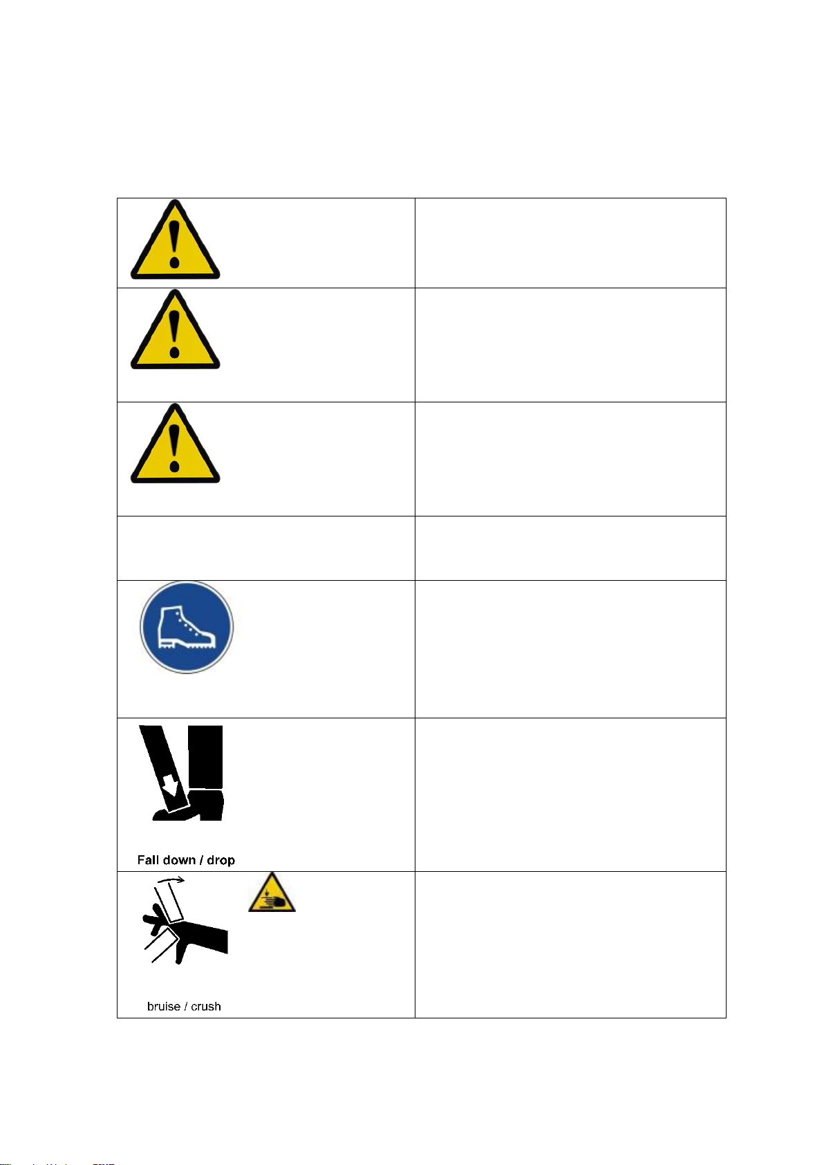
2.1.2 Markings in this user manual
Marking Meaning
Draws your attention on the handling and effect
of safety information.
WARNING
Makes you aware of a dangerous situation that
can cause you significant injury or death, if not
avoided.
CAUTION
Makes you aware of a dangerous situation that
can cause you mild to moderate injury, if not
avoided.
NOTE
Makes you aware of potential property damage
and other important information in connection
with your equipment.
Foot protection
Safety shoes:
Mandatory sign according to ANSI (according to
Z 535.3 - 2007)
Meaning: Foot protection
Fall down/drop: Falling down
Warning sign according to ANSI (according to Z
535.3 - 2007)
Meaning: Falling down / downward movement –
danger to feet
Danger of
Crushing
Bruise/ crush: Crushing
Warning sign according to ANSI (according to Z
535.3 - 2007)
Meaning: Risk of crushing for hands

Original user manual
12
2.2 Service address
MovieTech AG
Martin-Kollar-Str. 9
D-81829 Munich
E-mail: info@movietech.de
www.movietech.de
Tel.: +49 (0) 89 43 68 91 3
3. Safety precautions
3.1 General safety precautions - manufacturer
Before commissioning, ensure that you have read and understood the user manual.
Do not leave the assembled remote head unattended. Secure against unauthorized use.
The manufacturer’s specified limit values must be strictly adhered to. Any excess should be
avoided under all circumstances.
The remote head may not be assembled under the influence of alcohol, drugs or other
narcotics.
Only qualified persons may be assigned with the assembly and disassembly and operation of
the remote head. If necessary, the assignment must be stated in writing.
Beware of possible bruising during assembly and disassembly and during operation (please
see chapter structure and special warnings for each operating phase). Warning labels on the
product and the manual must be observed!
Ensure and guarantee the safe fixing of a camera on the remote head before each use. Use
additional straps for safe fixing.
Electrical equipment like monitors, must always be protected against moisture and humidity.
Never move the remote head mechanically by hand when switched on!

Original user manual
13
3.2 General safety precautions - Use
Follow the instructions on the use of maximum 25 kg camera weight in the 2-axis operation,
15kg camera weight in the 3-axis operation. Note warnings on the unit, special instructions on
stability and safe use.
Do not leave the assembled P10 unattended. Secure against unauthorized use.
Because of the danger of a lightning strike, adjust the operation when a storm approaches.
P10 may be used at an ambient temperature of -5 - +40°C.
Do not assemble and disassemble, if the maximal permissible wind velocity exceeds 50 km/h.
P10 is suited for studio and limited outdoor use. Avoid installing in a sandy, dusty, wet and
salty environment.
Avoid dashing the remote heads against any objects and obstacles, because of possible
damages to materials and the drive. Damaged parts, above all safety-related parts, must be
replaced by the manufacturer.
3.3 General safety precautions - check
Before each use, safety must be checked during operation by visual and functional testing
(according to DIN15999)
In particular, pay attention to the following criteria
unusual noises during movement,
deformations (e.g. bending, twisting),
damage (e.g. cracks, corrosion),
missing parts (e.g. retaining pins, fasteners)
defective clamp functions of the adjustment mechanisms
defective cables
In case of form changes or damages, contact the manufacturer!
Please observe all other safety instructions in the following chapters!
3.4 Intended use of P10
P10 may only be used according to its “intended use”.P10 is designed for horizontal and
vertical camera movements around the pivot point of the middle section. Therefore, the camera
thereby must weigh between 0.5 and 25kg (15kg in the 3-axis operation). Balancing the camera
on all three axes is required before each use to avoid damage to the drive units!

Original user manual
14
3.5 Personnel requirements
The operator of P10 should be able to control both the camera picture and the P10 radius of
action. The operation of P10 must be always assessed in terms of the safety-related aspects. The
responsibility for safe operation lies with the user. Distances between the camera and objects
must always be assessed properly in terms of safety to avoid accidents and damages. You must
assume a responsible approach to the product in the respective environment. The user must
familiarize himself with and understand the safety-related aspects of the operation using the user
manual.
General information for safety at work:
In operation, the P10 entails a risk to dash the head of an actor.
Within the P10 radius of action, only the access to the user, when mounting
the camera, is allowed! During the operation of P10, the radius of action should
be kept free.
Standing or sitting underneath an extension arm with a remote head P10
assembled thereon is not allowed for safety reasons!
Entering a prohibited area
3.6 Safety-related environmental conditions
The operation of P10 is suitable for the following environmental conditions:
In-studio operation and limited outdoor operation.
Avoid installing in a sandy, dusty, salty and wet environment!
Avoid operation under heavy rain, snowfall and in a strong windy or gusty environment !
The base should be even and stable for the necessary total weight loading of P10.
Always keep in mind that the pressure on a crane, dolly, or individual tripod legs under load –
if P10 is loaded increases on the ground many times.
Avoid installing P10 on snow, sand and swampy grounds.
3.7 Possible misuse
The following applications are not permitted for the P10:
Using cameras weighting over 25kg/ 2-axis (15kg/ 3-axis )
Using with untared and insecure cameras
Using P10 for holding lighting systems
Using P10 in sandy conditions
Using under water
Assembly and taring of the camera with the unit is turned on
Adjusting the drive modules with the unit turned on
Connecting and disconnecting individual cables with the unit turned on
Adjusting the drive modules with the unit turned on
The touch module must be protected against humidity

Original user manual
15
3.8 Residual hazards and protective measures
Transport / Storage:
When transporting the P10, make sure that no point loads rest on single parts.
The remote head should be stored in a dry area.
The remote head may not be stored in direct sunlight.
The remote head may not be transported or shipped without proper packaging.
The drive modules of the remote head may not be adjusted under load. Loads are always
adjusted prior to disassembly according to instructions.
All accessories should be disassembled for transport
4. Technical information
4.1 Technical data
Remote head P10 Digital
Activation: RS232
Motors: DC-Motor 24V
Power supply: 24V DC
Velocity: Vmax. 360° Pan 2-Axle ca. 4, 5 Sec.
Dead weight: 2-Axle Operation 12kg
3-Axle Operation 20kg
Connection: Euro mount taps 80mm (Optional: Mitchell adapter)
Frame dimensions: 2-ply frame 520x380mm
Payload: Payload 2-axis 25kg
Payload 3-axis 15kg
5.0 Optional accessories
Art. No. 8414-0
Single operator kit P10
Art. No. 8412-500
Power supply box
Art. No. 841210-0
Set of cables zoom/focus “Canon”
Art. No. 841212-0
Set of cables zoom/focus “Canon HD”
Art. No. 841220-0
Set of cables zoom/focus “Fujinon”
Art. No. 841215-0
Set of cables zoom/focus “Angenieux”

Original user manual
16
CAUTION
6.0 Mounting
Please open the transport case with caution. Use no sharp tools such as cutters, scissors etc that
may cause damage to the frame parts or the cable.
Please control the contents delivered with the delivery slip and list. For content list see page 5,6
The contents delivered include only the items illustrated!
In case of missing parts, inform the manufacturer.
6.1 Mounting P10 2 axes –Base frame with drive modules
The socket (mount) of the remote head has an outer diameter of
80mm.
Make sure that the Euro mount connection of P10 is inserted vertically
into the designated socket Mitchell clamping and that this is securely
closed!
Make sure that the crane or dolly to be operated with the P10 is
suitable for the given load!
Secure a mounted camera always with additional security straps
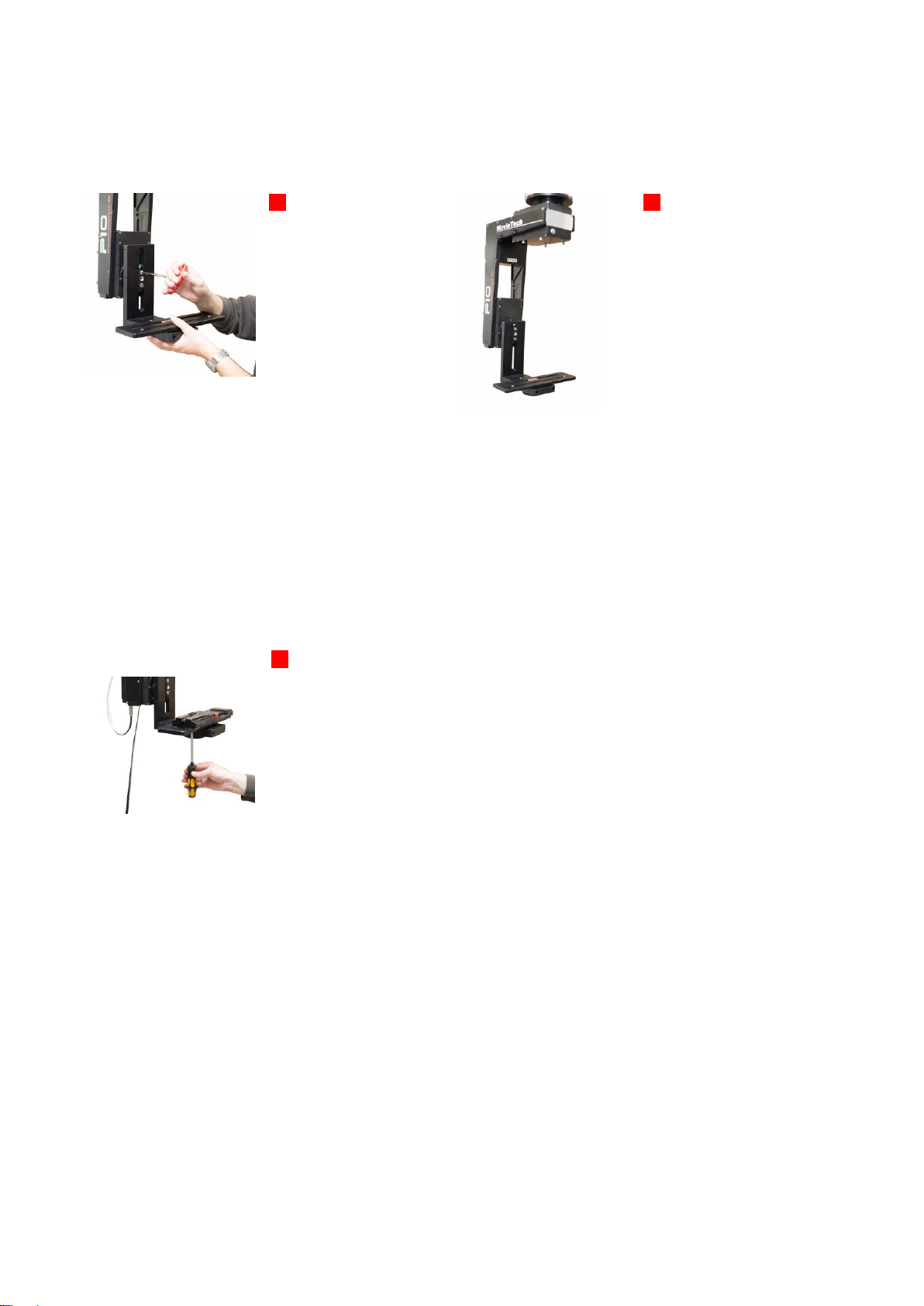
6.2 Mounting the P10 base blate
01
Install the base
plate.
A: Lay the
connection plate in
the slot
B: Lay the base
plate on top.
C: Screw star bolt
from the bottom
02
Complete
assembly
illustration
Base plate
is movable
horizontally
and vertically
03
Open the screw for
changing the postion of
the base plate in two
axis.
04
Positioning is depending
on the camera body
length and width.
The center of grafity of
the camera body (length
and width) has to be
positioned in the middle
of the pivot.

Original user manual
17
6.3 Positioning of the Tilt Drive Module
6.4 Positioning of the Tilt Drive Module
05
Positioning of the Tilt
drive vertically
Open the 4 Allen screws
with a wrench of size “3”
Please leave some
space for the assembly
of the connection cable
06
Tilt drive module may be
moved in height.
Tighten the screws
afterwards.
Do not remove the screwed stopper of the frame for safety reasons to prevent the sliding of
unsecured drive module!
Notice:
The positioning of the tilt module helps you to optimize the size of the frame depending on the camera type
you are using. A small frame size is preferred for a reduced mass.
07
Positioning gear
boxes horizontal
Open the 4 Allen screws
with a wrench of size “3”
Please leave some
space for the assembly
of the connection cable
08
Pan module may be
moved in longitudinal
position.
Tighten the screws
afterwards.
Do not remove the screwed stopper of the frame for safety reasons to prevent the sliding of
unsecured drive module!
Notice:
The positioning of the pan module helps you to optimize the size of the frame depending on the camera
type you are using. A small frame size is preferred for a reduced mass.
Original user manual
18
6.5 Positioning of the Tilt Clamp
6.6 Mounting a Snap Plate (not in the delivery included)
09
Positioning tilt clamp
The tilt clamp, is
adjustable in height for
the taring of the camera
Tighten the bolts
securely after
positioning
10
Lowest position
depending on the
camera body height.
The center of grafity of
the camera body has to
be positioned in the
middle of the pivot.
Notice:
The positioning of the camera in the center of graphity is very important to reduce the force on the tilt and
pan motor and gearing. If the camera is out of balance the circuit breaker will stop the operating
when the current flow is to high! (please check pos. xxx circuit breaker)
11
Mounting snap plate
Mount a snap plate or
similar camera plate on
the tilt module
Please check the center
of gravity (camerabody).
before mounting.
There are 2x 3/8” screws for the mounting included.
Notice:
Please switch off always the complete system before you mount the camera! The drive must be free in
the movement.
Original user manual
19
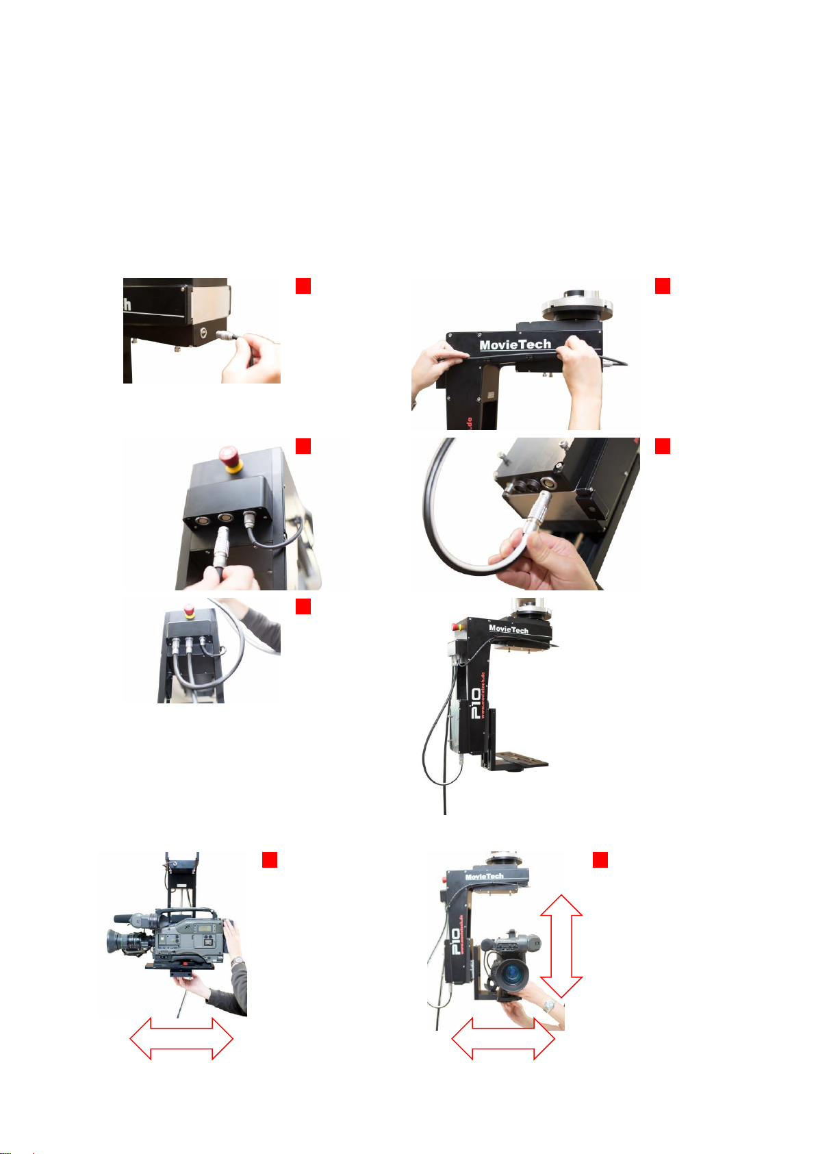
6.7 Mounting Pan/Tilt module cable
Note: The connector of the cable has red marks! Please bring these marks to the correct position
when plug in the cable!
12
Mount the Pan
connection
cable
13
The connection
sockets of the
Pan module are
located on the
bottom side of the
module
14
Mount Tilt
connection
cable
15
The connection
sockets of the Tilt
module are
located on the
bottom side of the
module
16
Mount Main
power cable
17
Positioning gear
boxes horizontal
The basic clamp tilt, is
adjustable in height for
the taring of the camera
Tighten the bolts
securely after
positioning
18
Lowest position
depending on the
camera body height.
The center of grafity of
the camera body has to
be positioned in the
middle of the pivot.

Original user manual
20
6.8 Mounting of zoom/focus cables
Zoom function of an lens with integrated motor
Focus function of a lens with integrated motor
Rec. on/off of a lens with zoom function
Ret. function shows the last seconds of footage
Caution –For the use of the zoom/focus/rec. function a broadcast lens with integrated motors is
needed, a cable set for the manufacturer Canon, Canon digital, Fujinon, Angenieux is required!
Art. No. 8470-2700 Canon standard cable set consisting of zoom cable XPin/focus cable XPin
Art. No. 8470-2900 Canon digital cable set consisting of XPin/focus cable XPin
Art. No. 8470-2800 Fujinon standard cable set consisting of XPin/focus cable XPin
Art. No. 8470-2600 Angenieux standard cable consisting of XPin/focus cable XPin
Notice:
The positioning of the camera in the center of graphity is very important to reduce the force on the pan
motor and gearing. If the camera is out of balance the circuit breaker will stop the operating when
the current flow is to high!
Connector for the focus
and zoom function at the
lens connecting plate
19
Lens with integrated
motors for zoom and
focus
For the P10 is a set of
cables for zoom/focus
for canon/canon
HD/Fujinon/Angenieux
as an option available
20
Connecting plate for
zoom and focus at the
P10 frame
Notice:
For using the zoom and focus function you need a broadcast lens with integrated motors!
Table of contents
Other MovieTech Professional Video Accessories manuals


