manuals.online logo
Brands
  1. Home
  2. •
  3. Brands
  4. •
  5. ulrich medical
  6. •
  7. Medical Equipment
  8. •
  9. ulrich medical Obelisc CS 2931 Series Configuration guide

ulrich medical Obelisc CS 2931 Series Configuration guide

obelisc™
vertebral body replacement
Assembly and disassembly instructions
with special cleaning instructions
2obelisc™Assembly and disassembly instructions
This document lists all of the assembly and disassembly instructions available for the obelisc system. The instruments
must be disassembled according to the manufacturer's instructions in order to guarantee the processing and storage.
The product descriptions in the component overview are listed in English according to the labeling on the instruments.
The user must ensure that the current versions of the system-related surgical technique and the "Processing
manual implants and instruments" UH 1100 are on hand and are followed. These are also available at:
www.ifu.ulrichmedical.com.
Notes on assembly and
disassembly instructions
3
1
2
3
4
8
12
obelisc™Assembly and disassembly instructions
obelisc™ Assembly and disassembly instructions for CS 2931-XX
obelisc™ Assembly and disassembly instructions for CS 2931G
obelisc™ Assembly and disassembly instructions for CS 2932-X
Contents
4
1
4
5
6
7
1
2
3
obelisc™Assembly and disassembly instructions
obelisc™
Assembly and disassembly instructions for
CS 2931-XX
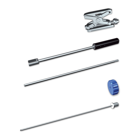
Components involved:
No. Product no. Product description
1 CS 2931-01 Holder, length 450 mm
2 CS 2931-06 Holder, length 360 mm
3 CS 2931-02 Expansion rod, length 450 mm
4 CS 2931-07 Expansion rod, length 360 mm
5 CS 2931-03 Locking rod, length 450 mm
6 CS 2931-08 Locking rod, length 360 mm
7 CS 2931-04 Turning knob
!Warning: The products
CS 2931-01 or -06 and
CS 2931-02 or -07 and
CS 2931-03 or -08 each constitute
an individual, coordinated
functional unit and may not be
exchanged for products of another
functional unit. If an exchange
takes place, the instrument may not
be used as its function cannot be
guaranteed.
Each product of a functional unit is
labeled with the same combination
of letters and numbers (e.g. "Al 09")
identifying the common grouping.
5
1
obelisc™Assembly and disassembly instructions
Assembly instructions
Assembling the inserter
CS 2931-01 or -06 is pushed over
CS 2931-02 or -07.
CS 2931-04 is attached to the back
of CS 2931-02 or -07. At the same
time, CS 2931-02 or -07 should be
held from the front.
Then CS 2931-03 or -08 is inserted
into CS 2931-01 or -06 from the
back. CS 2931-XX is now com-
pletely assembled.
6
1
obelisc™Assembly and disassembly instructions
Disassembly instructions
Note: CS 2931-XX must be
disassembled for cleaning and
storage on the tray.
Disassembling the inserter
CS 2931-03 or -08 is pulled
backwards out of CS 2931-01 or -06.
CS 2931-04 is pulled off of
CS 2931-02 or -07. At the same
time, CS 2931-02 or -07 should
be held from the front. Then
CS 2931-02 or -07 is removed from
CS 2931-01 or -06 in a forwards
direction.
obelisc™
Assembly and disassembly instructions for
CS 2931-XX
7
1
obelisc™Assembly and disassembly instructions
Special cleaning instructions
Manual cleaning
All lumens and cavities must be
rinsed out carefully and thoroughly.
Visual inspection
Finally, it must be checked whether
there is any visible soiling. If this is
the case, the previous steps must
be repeated.
Inserter maintenance
For their maintenance, movable
parts such as joints, hinges and
threaded parts should be treated
with suitable maintenance oil.
General
In addition, the general cleaning
instructions of the Processing
manual implants and instruments
UH 1100 also apply.
8
2
4
1
2
3
obelisc™Assembly and disassembly instructions
obelisc™
Assembly and disassembly instructions for
CS 2931G
Components involved:
No. Product no. Product description
1 CS 2931-10 Holder curved, length 450 mm
2 CS 2931-11 Expansion rod flexible, length 450 mm
3 CS 2931-12 Locking rod flexible, length 450 mm
4 CS 2931-04 Turning knob
9
2
[1]
[2]
[4]
[3]
[5]
[6]
[7]
obelisc™Assembly and disassembly instructions
Assembly instructions
CS 2931-11 is pushed into the back
of CS 2931-10 curved [1].
CS 2931-04 is attached to the
back of CS 2931-11 [2] and then
CS 2931-12 is inserted [3].
The instrument is now fully
assembled [4].
Disassembly instructions
CS 2931-12 is pulled backwards
out of CS 2931-10 [5].
CS 2931-04 is pulled off of
CS 2931-11 [6].
Then CS 2931-11 is removed
from CS 2931-10 in a backward
motion [7].
10
2
obelisc™Assembly and disassembly instructions
obelisc™
Assembly and disassembly instructions for
CS 2931G
Special cleaning instructions
Important: Excessive bending of
the flexible parts outside of the
holder should be avoided.
Manual cleaning
All lumens and cavities must be
rinsed out carefully and thoroughly.
The flexible part of CS 2931-12
must be rinsed at the rinse holes
with a disposable syringe.
Visual inspection
Finally, it must be checked whether
there is any visible soiling. If this
is the case, the previous steps
must be repeated. In particular the
flexible parts must be checked for
any soiling or damage.
Inserter maintenance
For their maintenance, movable
parts such as joints, hinges and
threaded parts should be treated
with suitable maintenance oil.
For other instructions see page 11
11
2
obelisc™Assembly and disassembly instructions
Instructions for machine
cleaning
Position CS 2931-10 at an angle
by placing the handle on a tray.
Position CS 2931-11 at an angle, by
placing the instrument on the tray
from the flexible part.
General
In addition, the general cleaning
instructions of the Processing
manual implants and instruments
UH 1100 also apply.
12
3
2
1
3
obelisc™Assembly and disassembly instructions
obelisc™
Assembly and disassembly instructions for
CS 2932-X
Components involved:
No. Product no. Product description
1 CS 2932-1 Handle for screwdriver, hex 3.5 mm
2 CS 2932-2 Shaft for screwdriver, hex 3.5 mm
3 CS 2932-3 Shaft flexible for screwdriver, hex 3.5 mm
13
3
obelisc™Assembly and disassembly instructions
Assembly instructions
Assembling the screwdriver for
locking screw
In order to assemble CS 2932-X,
CS 2932-2 or -3 is inserted into
CS 2932-1 until it clicks into place.
Check that the grip is secure.
Disassembly instructions
The screwdriver for locking screw
must be disassembled for cleaning
and also for storage on the tray.
Disassembling the screwdriver
for locking screw
Pulling on CS 2932-2 or -3 removes
it from CS 2932-1.
14
3
obelisc™Assembly and disassembly instructions
obelisc™
Assembly and disassembly instructions for
CS 2932-X
Manual cleaning
All lumens and cavities must be
rinsed out carefully and thoroughly.
Visual inspection
Finally, it must be checked whether
there is any visible soiling. If this is
the case, the previous steps must
be repeated.
General
In addition, the general cleaning
instructions of the Processing
manual implants and instruments
UH 1100 also apply.
15
obelisc™Assembly and disassembly instructions
Notes
pat. pend.
or/and
patented
ulrich GmbH & Co.KG l Buchbrunnenweg 12 l 89081 Ulm l Germany
Telephone: +49 (0)731 9654-0 l Fax: +49 (0)731 9654-2705
[email protected] l www.ulrichmedical.com
WS 2985-EN01_153908_R01/2019-06

This manual suits for next models

2

Other ulrich medical Medical Equipment manuals

ulrich medical Pezo PEEK cage Series Configuration guide

ulrich medical

ulrich medical Pezo PEEK cage Series Configuration guide

ulrich medical ADDplus anterior distraction device plus User manual

ulrich medical

ulrich medical ADDplus anterior distraction device plus User manual

ulrich medical uCentrum User manual

ulrich medical

ulrich medical uCentrum User manual
ulrich medical tezo titanium cage Series User manual

ulrich medical

ulrich medical tezo titanium cage Series User manual

ulrich medical Obelisc User manual

ulrich medical

ulrich medical Obelisc User manual

ulrich medical golden gate CS 3715 Configuration guide

ulrich medical

ulrich medical golden gate CS 3715 Configuration guide

ulrich medical tezo CS 3460 Series Configuration guide
ulrich medical

ulrich medical tezo CS 3460 Series Configuration guide

ulrich medical neon3 CS 3921 Series Configuration guide
ulrich medical

ulrich medical neon3 CS 3921 Series Configuration guide

Popular Medical Equipment manuals by other brands

Scosche RHYTHM24 user manual

Scosche

Scosche RHYTHM24 user manual

Eickemeyer KOWA SL-19 user manual

Eickemeyer

Eickemeyer KOWA SL-19 user manual

ResMed Swift FX user guide

ResMed

ResMed Swift FX user guide

Amiea Med EXCEED Instructions for use

Amiea Med

Amiea Med EXCEED Instructions for use

BTS Freeemg 1000 manual

BTS

BTS Freeemg 1000 manual

Bard Arctic Sun 5000 Operator's manual

Bard

Bard Arctic Sun 5000 Operator's manual

Roche CoaguChek INRange user manual

Roche

Roche CoaguChek INRange user manual

Weinmann OXYWAY Series Description and instructions for use

Weinmann

Weinmann OXYWAY Series Description and instructions for use

bort medical select 104 700 Instructions for use

bort medical

bort medical select 104 700 Instructions for use

Medit T-series Function manual

Medit

Medit T-series Function manual

Invacare SOLO 2 Quick reference guide

Invacare

Invacare SOLO 2 Quick reference guide

Hologic TruNode S-10 user manual

Hologic

Hologic TruNode S-10 user manual

Otto Bock 17LK3 Series Instructions for use

Otto Bock

Otto Bock 17LK3 Series Instructions for use

Masimo Rad-G Directions for use

Masimo

Masimo Rad-G Directions for use

HOFFEN IFS-8555 instruction manual

HOFFEN

HOFFEN IFS-8555 instruction manual

DIR Libra 8710 instruction manual

DIR

DIR Libra 8710 instruction manual

Invacare R8802 operating instructions

Invacare

Invacare R8802 operating instructions

Stryker Power-PRO IT 6516 Operation & maintenance manual

Stryker

Stryker Power-PRO IT 6516 Operation & maintenance manual

manuals.online logo
manuals.online logoBrands
  • About & Mission
  • Contact us
  • Privacy Policy
  • Terms and Conditions

Copyright 2025 Manuals.Online. All Rights Reserved.