AGFA DX-D 400 User manual

DX-D 400
User Manual
(type 5420 / 100)
Technical Publication
0232F EN 20191213


DX-D 400
User Manual
0232F EN 20191213
REVISION HISTORY
REVISION DATE REASON FOR CHANGE
AJAN 10, 2011 First edition
B OCT 16, 2013 IEC Standards Update and Grids Update
C MAR 09, 2015 Removed Detector Models
D OCT 15, 2018 New logo, new system label, Applied parts
warning, IEC fouth Edition, table Emergency
Stop images, new pedal overlay images, Tilting
Wall Stand Images.o.
E JUN 27, 2019 Handle color changes to Grey and Angle
indicator change when tilting to 61o
FDEC 12, 2019 New ON/OFF Box, and tethered Detector
handling
This Document is the English original version, edited and supplied by the manufacturer.
The Revision state of this Document is indicated in the code number shown at the bottom of this page.

DX-D 400
User Manual
0232F EN 20191213
ADVISORY SYMBOLS
The following advisory symbols will be used throughout this manual. Their
application and meaning are described below.
DANGERS ADVISE OF CONDITIONS OR SITUATIONS THAT
IF NOT HEEDED OR AVOIDED WILL CAUSE SERIOUS
PERSONAL INJURY OR DEATH.
ADVISE OF CONDITIONS OR SITUATIONS THAT IF NOT
HEEDED OR AVOIDED COULD CAUSE SERIOUS PERSONAL
INJURY, OR CATASTROPHIC DAMAGE OF EQUIPMENT OR
DATA.
Advise of conditions or situations that if not heeded or
avoided could cause personal injury or damage to equipment
or data.
Note .Alert readers to pertinent facts and conditions. Notes represent
information that is important to know but which do not necessarily
relate to possible injury or damage to equipment.

DX-D 400
User Manual
0232F EN 20191213 i
TABLE OF CONTENTS
Section Page
1 INTRODUCTION 1.........................................................
1.1 General Features 2...................................................
1.2 Product Identification 5................................................
1.3 Indications for Use 6..................................................
1.3.1 Intended Use 6................................................
1.3.2 Normal Use 6.................................................
1.3.3 Contraindications 6............................................
1.4 Applied Parts 7.......................................................
2 SAFETY AND REGULATORY INFORMATION 9..............................
2.1 General 9...........................................................
2.2 Responsibilities 12.....................................................
2.3 Maximum Permissible Dose (MPD) 13...................................
2.4 Radiation Protection 14.................................................
2.5 Monitoring of Personnel 16.............................................
2.6 safety symbols 17.....................................................
2.7 Regulatory Information 22..............................................
2.7.1 Certifications 22................................................
2.7.2 Environmental Statement on the Cycle of the Equipment or System 22
2.7.3 Mode of Operation 22...........................................
2.7.4 Protection Against Electric Shock Hazards 23......................
2.7.5 Protection against Harmful Ingress of Water or Particulate Matter 23...
2.7.6 Protection against Hazards of Ignition of Anaesthetic Mixtures 23.....
2.7.7 Protection Against Hazards from Unwanted or Excessive Radiation 23.
2.7.8 Designated Significant Zones of Occupancy 24.....................
2.7.9 Distribution of Stray Radiation 27.................................
2.8 Electromagnetic Compatibility (EMC) 30..................................

DX-D 400
User Manual
ii 0232F EN 20191213
Section Page
2.9 Quantitative Information 38............................................
2.9.1 Functional Tests Performed to Obtain the Quantitative Information 38..
2.10 Deterministic Effects 45................................................
2.11 Product Complaints 45.................................................
3 START UP AND SHUTDOWN 47.............................................
3.1 Start up with X-Ray Generator Control 47.................................
3.2 Shutdown Routine with X-Ray Generator Control 49........................
4 OPERATION 51............................................................
4.1 Floor Mounted Tube Stand 51...........................................
4.1.1 Column Rotation Control 51......................................
4.1.2 DX-D 400 Analog Control Panel 52................................
4.1.2.1 Vertical SID Reference Label 54...........................
4.1.3 DX-D 400 Digital Control Panel 55................................
4.1.4 Ralco Manual Collimator R225/R225 DHHS 58.....................
4.1.5 Ralco Automatic Collimator R225ACS 59..........................
4.2 Dosemeter Device (optional) 60.........................................
4.3 RAD Table 60.........................................................
4.3.1 RAD Table -- Fixed Height Table 60...............................
4.3.2 RAD Table -- Elevating Table 62..................................
4.3.3 Hand Grips (Optional) 65........................................
4.3.4 Compression Band (Optional) 66.................................
4.3.5 Lateral Detector Holder (Optional) 67..............................
4.3.6 Lateral Detector Holder on Table (Optional) 68......................
4.3.7 Lateral Detector Holder with Trolley 69.............................
4.4 RAD Wall Stand 72....................................................
4.5 Rad Wall Stand - Manual Tilting 73.......................................
4.5.1 Tilting of Receptor Assembly 75..................................
4.5.2 Rotation of Receptor Assembly 76................................
4.5.3 Arm Support (optional) 78........................................
4.5.4 Hand Supports (optional) 78......................................
DX-D 400
User Manual
0232F EN 20191213 iii
Section Page
4.6 Receptor Assembly (Table and Wall Stand) 79.............................
4.6.1 Travel of the Receptor Assembly (Table and Wall Stand) 79..........
4.6.2 Receptors 81...................................................
4.6.3 Tray for Cassette Film or CR (Table or Wall Stand) 82...............
4.6.4 Fixed Receptor Assembly (Table or Wall Stand) 83.................
4.6.5 Portable Receptor Assembly (Table or Wall Stand) 84...............
4.6.5.1 Portable Receptor Assembly with Rotating Tray 84...........
4.6.5.2 Portable Receptor Assembly with non-Rotating Tray 87.......
4.6.6 Grids 90.......................................................
4.6.7 Using and Maintaining the Digital Detector 91.......................
4.7 X-ray Beam Alignment with Respect to Patient 92..........................
5 DX-D TOUCH SCREEN CONSOLE 93........................................
5.1 Radiography and General Controls 96....................................
5.1.1 Power ON / OFF 96.............................................
5.1.2 Service Mode 96...............................................
5.1.3 Workstation Selection 97........................................
5.1.4 Focal Spot Indicator 98..........................................
5.1.5 Radiographic Parameters 99.....................................
5.2 Automatic Exposure Control (AEC) 103....................................
5.2.1 Rapid Termination 104............................................
5.3 Anatomical Programmer (APR) 105.......................................
5.4 Exposure Controls and Status Indicators 115...............................
5.5 Self-Diagnosis Indicators 116............................................
5.6 Heat Units 117.........................................................
5.7 Dosimetry (Optional) 117................................................
5.8 Error Codes 118........................................................
DX-D 400
User Manual
iv 0232F EN 20191213
Section Page
6 DX-D OVERLAY CONSOLE AND
DX-D OVERLAY CONSOLE WITH APR 123....................................
6.1 Radiography and General Controls 124....................................
6.1.1 Power ON / OFF 124.............................................
6.1.2 Workstations Selection 124.......................................
6.1.3 Focal Spot Indicators and Selectors 125............................
6.1.4 Radiographic Parameters 126.....................................
6.2 Automatic Exposure Control (AEC) 128....................................
6.2.1 Rapid Termination 129............................................
6.3 Anatomical Programmer (APR) (Optional) 129..............................
6.4 Exposure Controls and Indicators 132.....................................
6.5 X-Ray Handswitch 133..................................................
6.6 Heat Units 133.........................................................
6.7 Exposure Counters 133.................................................
6.8 Self-Diagnosis Indicators 134............................................
6.9 Error Codes 135........................................................
7 OPERATING SEQUENCES 139...............................................
7.1 Start-UP Routine 139...................................................
7.2 X-Ray Tube Warm-Up Procedure 139.....................................
7.3 Radiographic Operation 140.............................................
7.4 AEC Operation 141....................................................
7.4.1 How to Verify the Proper Functioning of the AEC 141.................
7.5 APR Operation 143....................................................
7.6 Fail-Safe Function 143..................................................
8 PERIODIC MANTEINANCE 145...............................................
8.1 Operator Tasks 145.....................................................
8.2 Service Tasks 146......................................................

DX-D 400
User Manual
0232F EN 20191213 v
Section Page
9 TECHNICAL SPECIFICATIONS 147...........................................
9.1 Environmental Requirements 147.........................................
9.2 X-ray System Positioners 147............................................
9.2.1 Power Line Requirements 147.....................................
9.2.2 Information Related to Radiation 148...............................
9.2.3 Physical Characteristics 148.......................................
9.3 X-Ray Generator 158...................................................
9.3.1 Factors 158.....................................................
9.3.2 Range of Radiographic Parameters 158.............................
9.3.3 Duty Cycle 158..................................................
9.3.4 Physical Characteristics 159.......................................
9.4 X-Ray Tubes 160.......................................................
9.5 Collimators 160........................................................
APPENDIX A GUIDELINES FOR PEDIATRIC APPLICATIONS A-1.....................
APPENDIX B ANATOMICAL PROGRAMMER MATRIX B-1............................
B.1 Available Language Matrix B-2...........................................
B.2 Record of the APR Loading Factors B-9...................................

DX-D 400
User Manual
vi 0232F EN 20191213

DX-D 400
User Manual
0232F EN 20191213 1
SECTION 1 INTRODUCTION
This manual contains all the necessary information to understand and operate
the DX-D 400 X-ray System. It provides a general description, safety
information, operating instructions and specifications concerning the
equipment. This manual is not intended to teach radiology or to make any type
of clinical diagnosis. It includes the different configuration possibilities;
Elevating Table or Fixed Height Table and Control Panel.
The Tube Support Column, the RAD Table and the RAD Wall Stand are
associated equipment to the X-ray Generator Unit.
Basically, the Rad System consists of the following associated subassemblies:
Tube Support with variable height, X-ray Tube, Collimator, RAD Table and RAD
Wall Stand. The RAD Table and the RAD Wall Stand can house AR (Analog
Radiography), CR (Computed Radiography) or DR (Digital Radiography).
The Control Panel of the Column is ergonomically built, equipped with controls
and indicators logically arranged and easily accessible. A soft thumb pressure
on the control buttons allows the linear and rotation movements.
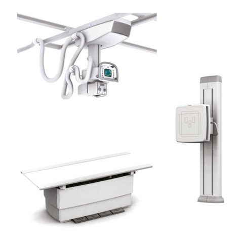
Illustration 1-1
DX-D 400 X-ray System
DX-D 400 with RAD Fixed Height Table,
Column with Analog Control Panel
and RAD Wall Stand
DX-D 400 with RAD Elevating Table,
Column with Digital Control Panel
and RAD Wall Stand -- Manual Tilting

DX-D 400
User Manual
20232F EN 20191213
The Generator Cabinet comprises the Power Module (which contains the
power and control components) and the High Voltage Transformer.
The operator controls and displays for radiographic operations are shown on
one of the following Consoles: the DX-D Overlay Console, the DX-D Overlay
Console with APR, the DX-D Touch Screen Console or the Software Console
of the NX Workstation. All functions, displays and controls are logically
arranged, easily accessible and identified to prevent confusion. Technique
factors and functions are selected by pushing the corresponding buttons or by
touching directly on the screen, as applicable.
The NX Workstation is used for imaging processing and diagnosis in CR or DR
Systems.
The High Frequency X-ray Generator provides all the advantages of high
frequency waveform Generators including lower patient dose, shorterexposure
times and greater accuracy and consistency.
The Generator is controlled by multiple microprocessors providing increased
exposure consistency, efficient operation and extended Tube life. A high level
of self-diagnosis greatly increases serviceability and reduces down time.
1.1 GENERAL FEATURES
The main features of the X-Ray System are:
A solid and ergonomic design.
Easy operation, security and precision of all positioning movements with
respect to patient.
Controls for Lock release of each equipment in the X--Ray System.
Floor Mounted Tube Stand:
GAnalog or Digital Control Panel.
GHorizontal motion of Column.
GColumn rotation in relation to its vertical axis.
GVertical motion of Tube-Collimator Assembly.
GTube-Collimator rotation in relation to its transverse axis. Manual
±150owith Detents (--90o,0
o,+90
o).
GTube-Collimator transverse motion related to its horizontal axis.
GManual Collimator or Automatic Collimator.
GDosemeter Device (optional).

DX-D 400
User Manual
0232F EN 20191213 3
RAD Table:
GFixed height or Elevating Table.
GRAD Table Receptor Assembly with longitudinal motion.
GIon Chamber connection (optional).
GFixed or Removable Grids.
GAccessories: Hand-Grips (pair), Compression Band, Lateral
cassette holder (24x30 cm or 35x43 cm.)
RAD Wall Stand:
GRAD Wall Stand Receptor Assembly adjusted with internal
counterweights.
GVertical motion of Receptor.
GIon Chamber connection (optional).
GFixed or Removable Grids.
GRight or left load (as per customer order).
GAccessories: Hand Grips and Arm Support.
RAD Wall Stand - Manual Tilting (optional):
GRAD Wall Stand Receptor Assembly adjusted with internal
counterweights.
GVertical motion of Receptor.
GTilting Receptor (+90o-- 2 0 o).
GIon Chamber connection (optional).
GFixed or Removable Grids.
GRight or left load (as per customer order).
GAccessories: Hand Grips and Arm Support.
The Handgrips must not be positioned in the trajectory of the
X--Ray beam.
Note .

DX-D 400
User Manual
40232F EN 20191213
X-Ray Generator:
GConstant potential high frequency.
GThree point control by selecting kVp, mA and ms, two point control
by selecting kVp and mAs (no AEC), or one point control by
selecting kVp with AEC operations.
GAnatomical Programmer (APR) for six patient sizes (three adults
and three children), with pre-programmed anatomical views for
automatic selection. The operator may manually modify all the
original APR techniques and store them for later use.
GAutomatic Exposure Control (AEC).
GRapid Termination function.
GFail-safe functionfor the detection of the correct alignment of
the Tube-Collimator / Receptor with respect to the selected
workstation.
GTwo Buckys or DR Detectors can be directly connected to the
Generator.
GSelf-diagnosis indicators identify malfunctions in the system.
GTube protection circuitry prolongs Tube life and increases system
performance.
GEquipped with closed loop control of X-ray Tube current, kVp and
filaments, which minimizes potential errors and the need for
readjustments.
GAutomatic line compensation due to closed loop operation of X-ray
Tube current and kVp.

DX-D 400
User Manual
0232F EN 20191213 5
1.2 PRODUCT IDENTIFICATION
The major items in the equipment have some identification labels attached to
them which provide the following manufacturer and product information.
Product.
Model.
Volts (V), Line Phases, Frequency (Hz), and Power (kVA, kW).
Date of manufacture.
Serial number.
Reference.
Manufacturer.
Place of manufacture.
Certification.
Illustration 1-2
Identification Labels

DX-D 400
User Manual
60232F EN 20191213
1.3 INDICATIONS FOR USE
1.3.1 INTENDED USE
This equipment is intended for medical prescription use by qualified personnel
only.
The DX-D 400 is an equipment designed for general radiography in hospitals,
clinics and medical practices to provide X-ray radiographic images of the
skeleton, skull, chest, abdomen, extremities and other body parts for
diagnostic.
Images can be obtained with the patient in the sitting, standing or lying position.
Examinations can be performed to any kind of patient group. Patients may be
physically abled, disabled, immobilized or shocked.
This DX-D 400 contributes to the metrics of imaging performance ensuring the
efficient use of radiation.
As example of X-ray image receptors types that can be used: Cassette with
Film, CR (Computed Radiography) or Digital Detector.
1.3.2 NORMAL USE
The Normal Use of this equipment is defined as the Intended Use plus the
Maintenance and Service tasks.
1.3.3 CONTRAINDICATIONS
Do not use the equipment for any purposes other than those for which it is
intended. Operation of the equipment for unintended purposes could lead to
fatal or other serious injury.
This equipment is not intended for mammography applications.
This equipment is not especifically designed for pediatric purposes; if children
are to be examined, they should always be accompanied by an adult.

DX-D 400
User Manual
0232F EN 20191213 7
1.4 APPLIED PARTS
Applied Parts refer to parts of the medical equipment that in Normal Use
necessarily comes into physical contact with the patient for the medical
equipment to perform its function. This RAD equipment includes the following
Applied Parts:
Tabletop of the RAD Table.
Tabletop of the RAD Wall Stand.
Hand Grips (optional).
Arm Support (optional).
Compression Band (optional).
Lateral Cassette Holders (optional).
Other accessories.
BEAR IN MIND THAT SOME APPLIED PARTS MAY HEAT UP
TO 48oC (118.4oF) WHEN THE AMBIENT TEMPERATURE
FOR OPERATION IS ON THE LIMIT. THIS IS COMPLETELY
NORMAL AND DOES NOT MEAN A MALFUNCTION OF THE
EQUIPMENT.

DX-D 400
User Manual
80232F EN 20191213
This page intentionally left blank.

DX-D 400
User Manual
0232F EN 20191213 9
SECTION 2 SAFETY AND REGULATORY INFORMATION
This section describes the safety considerations, general precautions for
patient, operator and equipment in order to perform a safe operation and
service tasks.
Regulatory information and symbols used in the equipment are detailed in this
section to operate it safely.
2.1 GENERAL
FOR CONTINUE SAFE USE OF THIS EQUIPMENT FOLLOW
THE INSTRUCTIONS IN THIS OPERATING MANUAL. BOTH
OPERATOR AND SERVICE PERSONNEL HAVE TO STUDY
THIS MANUAL CAREFULLY, INSTRUCTIONS HEREIN
SHOULD BE THOROUGHLY READ AND UNDERSTOOD
BEFORE ATTEMPTING TO PLACE THE EQUIPMENT IN
OPERATION, ESPECIALLY THE INSTRUCTIONS
CONCERNING SAFETY, REGULATIONS, DOSAGE AND
RADIATION PROTECTION. KEEP THIS OPERATING MANUAL
WITH THE EQUIPMENT AT ALL TIMES AND PERIODICALLY
REVIEW THE OPERATING AND SAFETY INSTRUCTIONS.
TECHNICAL INSTRUCTIONS FOR SERVICE PERSONNEL
SUCH AS PRE-INSTALLATION REQUIREMENTS,
INSTALLATION, CALIBRATION OR MAINTENANCE ARE
DESCRIBED IN THE RESPECTIVE CHAPTERS OF THE
PRE-INSTALLATION AND SERVICE MANUALS PROVIDED
WITH THIS EQUIPMENT.
PLEASE STUDY THIS MANUAL AND THE MANUALS FOR
EACH SYSTEM COMPONENT TO BE FULLY AWARE OF ALL
THE SAFETY AND OPERATIONAL REQUIREMENTS.

DX-D 400
User Manual
10 0232F EN 20191213
OPERATOR AND SERVICE PERSONNEL AUTHORIZED TO
USE, INSTALL, CALIBRATE AND MAINTAIN THIS
EQUIPMENT MUST BE AWARE OF THE DANGER OF
EXCESSIVE EXPOSURE TO X-RAY RADIATION. IT IS
VITALLY IMPORTANT THAT EVERYONE WORKING WITH
X-RAY RADIATION IS PROPERLY TRAINED, INFORMED ON
THE HAZARDS OF RADIATION AND TAKE ADEQUATE
STEPS TO ENSURE PROTECTION AGAINST INJURY.
OPERATOR MUST HAVE SUFFICIENT KNOWLEDGE TO
COMPETENTLY PERFORM THE DIFFERENT DIAGNOSTIC
IMAGING PROCEDURES WITH X-RAY DEVICES. THIS
KNOWLEDGE IS ACQUIRED THROUGH A VARIETY OF
EDUCATIONAL METHODS INCLUDING CLINICAL WORKING
EXPERIENCE, AND AS PART OF MANY COLLEGE AND
UNIVERSITY RADIOLOGIC TECHNOLOGY PROGRAMS IN
ACCORDANCE WITH LOCAL LAWS OR REGULATIONS.
SERVICE PERSONNEL MUST HAVE SUFFICIENT
KNOWLEDGE TO COMPETENTLY PERFORM THE SERVICE
TASKS RELATED TO X-RAY DEVICES AND PARTICULARLY
TO THE EQUIPMENT DESCRIBED IN THIS MANUAL. THIS
KNOWLEDGE IS ACQUIRED THROUGH A VARIETY OF
EDUCATIONAL METHODS FOR TECHNICIANS IN
ACCORDANCE WITH LOCAL LAWS OR REGULATIONS,
INCLUDING SPECIFIC TRAINING ON THIS EQUIPMENT.
X-RAY EQUIPMENT IS DANGEROUS TO BOTH PATIENT AND
OPERATOR UNLESS PROTECTION MEASURES ARE
STRICTLY OBSERVED. IF THE EQUIPMENT IS NOT
ACCURATELY USED, IT MAY CAUSE INJURY.
ALTHOUGH X-RADIATION CAN BE HAZARDOUS, X-RAY
EQUIPMENT DOES NOT POSE ANY DANGER WHEN IT IS
PROPERLY USED.
Other manuals for DX-D 400
1
This manual suits for next models
1
Table of contents
Other AGFA Medical Equipment manuals

AGFA
AGFA Drystar 4500 Plug & Play User manual

AGFA
AGFA CR 35-X User manual

AGFA
AGFA CR User manual

AGFA
AGFA DR 100e User manual

AGFA
AGFA CRHD5.0 User manual

AGFA
AGFA DX-D 10C User manual

AGFA
AGFA DX-D 40C User manual

AGFA
AGFA Drystar 5302 Technical manual

AGFA
AGFA EASYLIFT User manual

AGFA
AGFA DR 100e User manual