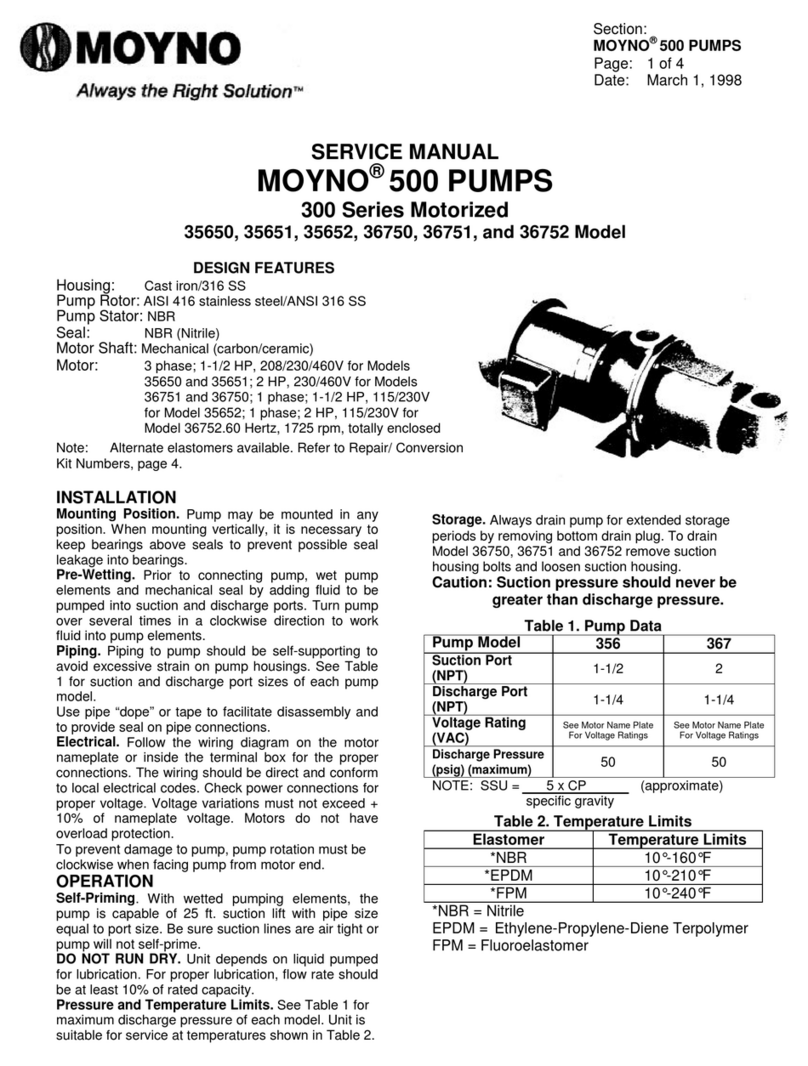
2
2. Stator torn; possible excessive pressure: Replace
stator; check pressure at discharge port.
3. Wrong rotation: Rotation must be clockwise when
facing pump from motor end. Reverse the connections
of any two line leads to the motor.
Pump Overloads.
1. Excessive discharge pressure: Check pressure at
discharge port for maximum ratings given in Table 1.
2. Fluid viscosity too high: Limit fluid viscosity to 700 CP
or 3700 SSU.
Noisy Operation.
1. Suction line too small: Check pipe size. Be sure lines
are free from obstructions.
2. Pump cavitates: Pump speed is 1750 RPM. Viscosity
of fluid should not exceed 700 CP or 3700 SSU.
3. Insufficient mounting: Mount to be secure to a firm
base. Vibration induced noise can be reduced by
using mount pads and short sections of hose on
suction and discharge ports.
Magnet De-Coupling.
1. High torque due to excessive pressure. Turn the pump
off and restart it. If magnet is still de-coupled, bleed
the pressure from the discharge. If problem persists,
disassemble unit and inspect parts.
2. High torque due to high viscosity product. Turn the
pump off, flush it with water. Check the viscosity of the
product that is being pumped. Viscosity of fluid should
not exceed 700 CP or 3700 SSU.
PUMP DISASSEMBLY
WARNING: Before disassembling pump, disconnect
power source and thoroughly bleed
pressure from system. Failure to do so
could result in electric shock or serious
bodily harm.
The magnets used to drive this pump are
powerful. Do not place your hands or
fingers in between the magnets at any time
during the assembly or disassembly
procedure.
1. Remove four socket head cap screws (3) connecting
the drive adapter (2) to the motor (1).
2. Remove entire pump assembly from the motor (1) and
outer magnet (4). Due to the magnet, there will be
some significant resistance when trying to pull the
pump assembly/inner magnet from the outer magnet
(4) and motor (1).
3. Place the pump assembly with the drive adapter (2)
bore flat on a table.
4. Remove four socket head cap screws (20) connecting
the suction housing (19) to the stator housing (17).
5. Remove the suction housing (19) from the stator
housing (17) and remove the O-ring (8) from the
suction housing (17).
6. Remove the eight socket head cap screws (15)
connecting the stator housing (17) to the discharge
housing (14).
7. Remove the stator housing (17).
8. Remove the thrust bushing (11) and rotor bushing (12)
from the rotor (22) and rotor shaft (10).
9. Remove stator (21) and stator ring (23) (on 331 and
332 models only).
10. Remove the thrust washer (11) from the rotor shaft (10).
11. Remove the rotor (22), inner magnet (9), shaft bushing
(13), and rotor end bushing (12) as an assembly.
12. Remove the rotor bushing (12) from the rotor (22), being
careful not to damage it. NOTE: Rotor shaft (10), thrust
washer (11) and end bushing (12) are all very fragile.
13. Press the inner magnet (9) off of the rotor (22).
14. Remove the shaft bushing (13) from the drive end side
of the rotor (22).
15. Remove rotor shaft (10) and thrust washer (10) from the
drive adapter (2)
16. Remove eight socket head cap screws (15) and nuts
(16) connecting the discharge housing (14) to the drive
adapter (2).
17. Remove the discharge housing (14) from the drive
adapter (2).
18. Remove the spacer plate (5) and magnet casing (6)
from the drive adapter (2)
19. Remove the outer magnet (4) from the motor (1) by
loosening set screws in the outer magnet (4) and sliding
the outer magnet (4) off of the motor drive shaft.
PUMP ASSEMBLY
1. Place the drive adapter (2) on a table; the motor side of
the drive adapter should be flat on the table.
2. Place the spacer plate (5) onto the drive adapter (2).
3. Place magnet casing (6) into the spacer plate (5).
4. Place O-ring (7) onto the magnet casing (6).
5. Place the discharge housing (14) onto the drive adapter
(2).
6. Place one thrust washer (11) into the bore in the magnet
casing (6) and place the rotor shaft (10) through the
washer into the bore, making sure the flat in the rotor
shaft (10) lines up with the flat in the thrust washer (11)
and bore.
7. Press the shaft bushing (13) into the magnet side of the
rotor (22).
8. Press the rotor (22) into the inner magnet (9), making
sure the flat on the rotor lines up with the flat on the ID
of the magnet.
9. Place the rotor (22), magnet (9), and shaft bushing (13)
assembly onto the rotor shaft (10).
10. Install the stator ring (23) (Note: this is only supplied
on the 331 and 332 models) into the suction side of the
stator (21) if applicable. Then install the stator (21) onto
the rotor (22).
11. Place the rotor bushing (12) into the end of the rotor
(22).
12. Place the stator housing (17) over the stator (21).
13. Place second thrust washer (11) onto rotor shaft (10),
making sure that the flat in the washer lines up with the
flat in on the rotor shaft (10).
14. Place the O-ring (8) onto the suction housing (19).
15. Place the suction housing (19) and O-ring (8) onto stator
housing, making sure that the flat in the bore of the
suction housing lines up with the flat machined onto the
rotor shaft.
16. Align all bolt holes for the entire assembly.
17. Using eight socket button head cap screws (15) and
nuts (16) secure the discharge housing (14) to the drive
adapter (2).


