moyno 35650 User manual

Section:
MOYNO® 500 PUMPS
Page: 1 of 4
Date: March 1, 1998
SERVICE MANUAL
MOYNO® 500 PUMPS
300 Series Motorized
35650, 35651, 35652, 36750, 36751, and 36752 Model
DESIGN FEATURES
Housing: Cast iron/316 SS
Pump Rotor: AISI 416 stainless steel/ANSI 316 SS
Pump Stator: NBR
Seal: NBR (Nitrile)
Motor Shaft: Mechanical (carbon/ceramic)
Motor: 3 phase; 1-1/2 HP, 208/230/460V for Models
35650 and 35651; 2 HP, 230/460V for Models
36751 and 36750; 1 phase; 1-1/2 HP, 115/230V
for Model 35652; 1 phase; 2 HP, 115/230V for
Model 36752.60 Hertz, 1725 rpm, totally enclosed
Note: Alternate elastomers available. Refer to Repair/ Conversion
Kit Numbers, page 4.
INSTALLATION
Mounting Position. Pump may be mounted in any
position. When mounting vertically, it is necessary to
keep bearings above seals to prevent possible seal
leakage into bearings.
Pre-Wetting. Prior to connecting pump, wet pump
elements and mechanical seal by adding fluid to be
pumped into suction and discharge ports. Turn pump
over several times in a clockwise direction to work
fluid into pump elements.
Piping. Piping to pump should be self-supporting to
avoid excessive strain on pump housings. See Table
1 for suction and discharge port sizes of each pump
model.
Use pipe “dope” or tape to facilitate disassembly and
to provide seal on pipe connections.
Electrical. Follow the wiring diagram on the motor
nameplate or inside the terminal box for the proper
connections. The wiring should be direct and conform
to local electrical codes. Check power connections for
proper voltage. Voltage variations must not exceed +
10% of nameplate voltage. Motors do not have
overload protection.
To prevent damage to pump, pump rotation must be
clockwise when facing pump from motor end.
OPERATION
Self-Priming. With wetted pumping elements, the
pump is capable of 25 ft. suction lift with pipe size
equal to port size. Be sure suction lines are air tight or
pump will not self-prime.
DO NOT RUN DRY. Unit depends on liquid pumped
for lubrication. For proper lubrication, flow rate should
be at least 10% of rated capacity.
Pressure and Temperature Limits. See Table 1 for
maximum discharge pressure of each model. Unit is
suitable for service at temperatures shown in Table 2.
Storage. Always drain pump for extended storage
periods by removing bottom drain plug. To drain
Model 36750, 36751 and 36752 remove suction
housing bolts and loosen suction housing.
Caution: Suction pressure should never be
greater than discharge pressure.
Table 1. Pump Data
Pump Model 356 367
Suction Port
(NPT) 1-1/2 2
Discharge Port
(NPT) 1-1/4 1-1/4
Voltage Rating
(VAC) See Motor Name Plate
For Voltage Ratings See Motor Name Plate
For Voltage Ratings
Discharge Pressure
(psig) (maximum) 50 50
NOTE: SSU = 5 x CP (approximate)
specific gravity
Table 2. Temperature Limits
Elastomer Temperature Limits
*NBR 10°-160°F
*EPDM 10°-210°F
*FPM 10°-240°F
*NBR = Nitrile
EPDM = Ethylene-Propylene-Diene Terpolymer
FPM = Fluoroelastomer

TROUBLE SHOOTING
WARNING: Before making adjustments,
disconnect power source and
thoroughly bleed pressure from
system. Failure to do so could result
in electric shock or serious bodily
harm.
Failure To Pump.
1. Motor will not start: Check power supply. Voltage
must be ± 10% of nameplate rating when motor is
in locked rotor condition.
2. Motor runs and thermally kicks out: Check for
excessive pressure. Increase ventilation to motor.
Do not use less than #14 wire size.
3. Stator torn; possible excessive pressure: Replace
stator, check pressure at discharge port.
4. Flexible joint broken; possible excessive pressure:
Replace joint, check pressure at discharge port.
5. Wrong rotation: Rotation must be clockwise when
facing pump from motor end. Reverse the
connections of any two line leads to the motor.
6. Excessive suction lift or vacuum.
Pump Overloads.
1. Excessive discharge pressure: Check pressure at
discharge port for maximum ratings given in Table
2. Fluid viscosity too high: Limit fluid viscosity to 100
CP or 500 SSU.
Noisy Operation.
1. Excessive suction lift or vacuum: Maximum suction
lift is 25 feet for water.
2. Suction line too small: Check pipe size. Be sure
lines are free from obstructions.
3. Pump cavitates: Pump speed is 1725 rpm.
Viscosity of fluid should not exceed 100 CP or 500
SSU.
4. Flexible joint worn: Replace joint. Check pressure
at discharge port.
5. Insufficient mounting: Mount to be secure to a firm
base. Vibration induced noise can be reduced by
using mount pads and short sections of hose on
suction and discharge ports.
Seal Leakage.
1. Leakage at startup: If leakage is slight, allow pump
to run several hours to let faces run in.
2. Persistent seal leakage: Faces may be cracked
from freezing or thermal shock. Replace seal.
Pump Will Not Prime.
1. Air leak on suction side: Check pipe connections.
PUMP DISASSEMBLY
WARNING: Before disassembling pump,
disconnect power source and
thoroughly bleed pressure from
system. Failure to do so could result
in electric shock or serious bodily
harm.
1. Disconnect power source.
2. Remove suction and discharge piping.
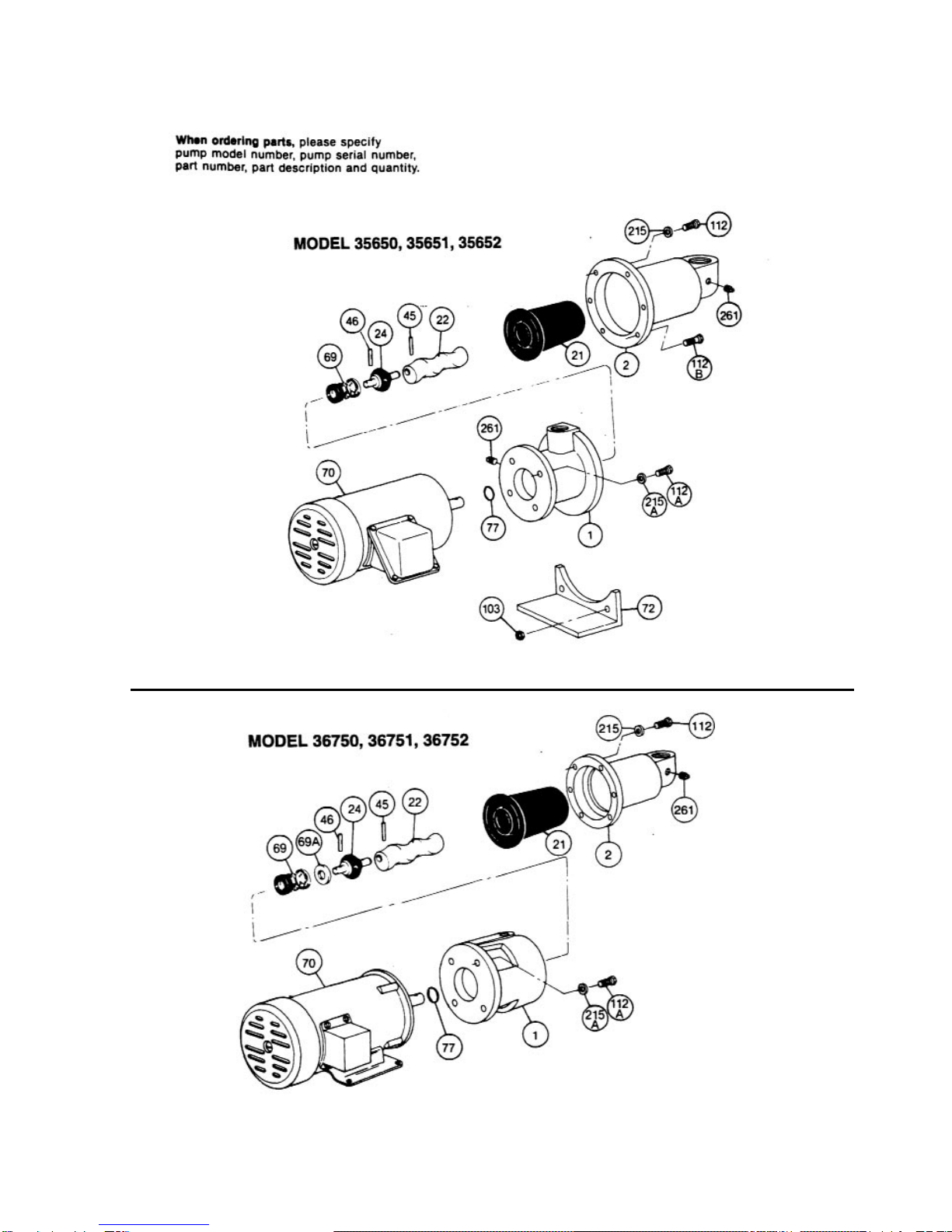
3. Remove screws (112) holding suction housing (2)
to discharge housing (1). Remove suction housing
(2) and stator (21).
4. Rotor (22) can be detached from flexible joint (24)
by using a punch to remove rotor pin (45). Support
joint when removing pin.
5. Flexible joint (24) can be removed from motor
shaft by using a punch through the discharge port
to remove shaft pin (46).
6. Carefully slide mechanical seal (69) off motor
shaft.
7. Remove discharge housing (1) from motor (70) by
removing screws (112A and 112C) and washers
(215).
8. Carefully pry seal seat out of discharge housing
(1). If any part of mechanical seal (69) is worn or
broken, the complete assembly should be
replaced. Seal components are matched parts and
not interchangeable.
9. Remove slinger ring (77).
PUMP ASSEMBLY
1. Replace slinger ring (77).
2. Attach discharge housing (1) to motor (70) using
lock washers (215) and body screws (112A).
3. Install mechanical seal (69) using the following
procedures:
a. Clean and oil sealing faces using light oil (not
grease).
Caution: Do not use oil on EPDM parts.
Substitute glycerin or soap and water.
b. Oil the outer surface of seal seat, and push
assembly over motor shaft into the bore of the
discharge housing (1) seating it firmly and
squarely.
c. After cleaning and oiling the shaft, slide the
seal body along the shaft until it meets the seal
seat.
d. Install seal spring and spring retainer on shaft.
4. On Model 367, position seal spacer (69A) on
motor shaft with slots away from seal (69).
5. Pin flexible joint (24) to motor shaft with shaft pin
(46) using a punch through the discharge port.
6. Pin rotor (22) to flexible joint using rotor pin (45).
Support joint while installing pin.
7. Slide stator (21) on rotor (22) carefully locating
stator flange in housing groove.
8. Secure stator (21) and suction housing (2) to
discharge housing (1) using screws (112).
9. Proceed as in installation instructions.
Page 2

Page 3

PARTS LIST Pump Model NumbersItem
No. Description 35650 35651 35652 36750 36751 36752
1 Discharge Housing 350-0632-007 350-0632-000 350-0632-007 340-0951-007 340-0951-000 340-0951-007
2 Suction Housing 350-0489-000 350-0280-000 350-0489-000 350-0302-007 350-0302-000 350-0302-007
*21 Stator 340-3505-120 340-3506-120
*22 Rotor 320-6392-015 320-6392-000 320-4431-000 330-3077-000 330-2042-000 330-3077-000
24 Flexible Joint 320-1618-000 320-1749-000
*45 Rotor Pin 320-4069-003 320-4439-002
*46 Motor Pin 320-4069-005 320-4439-001
*69 Mechanical Seal 320-3945-000 320-1750-000
69A Seal Spacer 320-1737-000
70 Motor 330-7845-003 330-7845-000 330-8054-002 330-2802-004 300-2802-001 330-8053-004
72 Motor Support 320-4446-000
77 Slinger Ring 320-6385-000
103 Nuts (2 req.) 614-0010-111 (3/8-16)
112 Screw, Hex Hd 619-1530-161 (3/8-16 x 1) (4 req.) 619-1530-161 (3/8-16 x 1) (6 req.)
112A Screw, Hex Hd (4 req.) 619-1530-161 (3/8-16 x 1) 619-1550-161 (1/2-13 x 1)
112B Screw, Hex Hd (2 req.) 320-6918-000 (3/8-16 x 1-3/4)
215 Lock Washer 623-0010-411 (3/8) (4 req.) 623-0010-411 (3/8) (6 req.)
215A Lock Washer (4 req.) 623-0010-411 (3/8) 623-0010-431 (1/2)
261 Pipe Plug 610-0120-011 (1/8 NPT)
* Recommended spare parts
REPAIR/CONVERSION KIT NUMBERS (For cast iron pumps only)
Model 35651 Model 36751
Item
No Description NBR EPDM FPM NBR EPDM FPM
–KitNo. 311-9123-000 311-9125-000 311-9126-000 311-9060-000 311-9036-000 311-9124-000
21 •Stator 340-3505-120 340-3505-320 340-3505-520 340-3506-120 340-3506-320 340-3506-520
24 •Joint 320-1618-000 320-6508-000 320-6509-000 320-1749-000 320-6378-000 320-6515-000
69 •Seal 320-3945-000 320-6380-000 320-6510-000 320-1750-000 320-6390-000 320-6517-000
46 •Pin (Motor) 320-4069-005 320-4439-001
45 •Pin (Rotor) 320-4069-003 320-4439-002
*NBR = Nitrile
EPDM = Ethylene-Propylne-Diene Terpolymer
FPM = Fluoroelastomer
ABRASION RESISTANT SEALS
Models
Elastomer 356 367
NBR 320-6505-000 320-6511-000
EPDM 320-6506-000 320-6512-000
FPM 320-6507-000 320-6513-000
© 1999 by Moyno, Inc.
® Moyno is a registered trademark of Moyno Inc. Printed in U.S.A
.
Page 4

Double The Length Of Your
Moyno Pump Warranty For FREE!
For your free pump warranty extension, choose from one of the three options below:
1. Go to www.moyno.com and fill out the registration form online
2. Mail this form by placing it in an envelope and sending it to: Moyno, Inc.
Attn: Tish Wilson
P. O. Box 960
3. Fax this form to 937-327-3177
Springfield, OH 45501-0960
U.S.A.
Thank you for choosing a Moyno Pump. Please take the time to complete this warranty registration form.Upon receipt
of your form, your standard limited warranty on defective material and workmanship will be extended to twice the standard
period of time at no additional cost to you. We appreciate your business and look forward to serving you in the future.
Always Insist on Genuine Moyno Replacement Parts!
Moyno®Pump Warranty Registration
Pump Model # Pump Serial #
Purchased From Date Purchased
Your Name Your Title
Your Company Name
Address
City/State (Province)/Zip Code
Phone Number Fax Number
E-mail
Application for Which This Pump Was Purchased
Material Flow Rate Process Temperature
Operating Speed Viscosity pH Value
Hours Operated per Day Continuous Intermittent
Discharge Pressure Suction Pressure NPSH Available
Percent of Solids Particle Size Abrasion Rating
How Did You First Hear of Moyno Pumps?
Advertisement Postcard Trade Show Referral
Distributor Salesperson Previous Experience With Moyno Pumps Other – Explain Below
Thank You!
❑
❑❑
❑❑
❑
❑
MOYNO
™
This manual suits for next models
5
Table of contents
Other moyno Water Pump manuals