moyno 2000 CC User manual

MOYNO®
2000CCPumps
SERVICE MANUAL

TABLE OF CONTENTS
Page
1-1. INTRODUCTION...............................................................................................................................................1
1-2. General..................................................................................................................................................1
1-3. Scope ....................................................................................................................................................1
1-4. Nameplate Data.....................................................................................................................................1
1-5. Pump Rotation.......................................................................................................................................1
1-6. Model Number.......................................................................................................................................1
2-1. INSTALLATION................................................................................................................................................2
2-2. General..................................................................................................................................................2
2-3. Piping.....................................................................................................................................................2
2-4. Foundation.............................................................................................................................................2
3-1. OPERATION ...................................................................................................................................................2
3-2. Initial Check...........................................................................................................................................2
3-3. Start-up..................................................................................................................................................2
3-4. Packing Leakage...................................................................................................................................2
4-1. MAINTENANCE................................................................................................................................................2
4-2. General..................................................................................................................................................2
4-3. Packing Adjustment...............................................................................................................................2
4-4. Packing Replacement............................................................................................................................3
5-1. DISASSEMBLY ................................................................................................................................................3
5-2. Disconnect Pump...................................................................................................................................3
5-3. Stator Removal......................................................................................................................................3
5-4. Suction Housing Removal .....................................................................................................................3
5-5. Rotor/Con Rod/Drive Shaft Assembly Removal ....................................................................................3
5-6. Packing Housing Removal......................................................................................................................4
5-7. Seal Housing Removal...........................................................................................................................4
5-8. Rotor, Driveshaft, and Connecting Rod Disassembly.............................................................................4
5-9. Drive Adapter/Gearmotor Removal........................................................................................................4
5-10. Cleaning ...............................................................................................................................................4
6-1. INSPECTION ....................................................................................................................................................4
6-2. Drive Shaft and Packing/Seals ..............................................................................................................4
6-3. Rotor......................................................................................................................................................4
6-4. Stator.....................................................................................................................................................4
6-5. All Other Parts .......................................................................................................................................4
7-1. ASSEMBLY ......................................................................................................................................................5
7-2. Lubrication During Assembly.................................................................................................................5
7-3. Driveshaft and Rotor Gear Joint Assembly............................................................................................5
7-4. Drive Adapter Assembly........................................................................................................................5
7-5. Pumps with Single Mechanical Seal......................................................................................................5
7-6. Pumps with Compression Packing ........................................................................................................6
7-7. Pumps with Double or Cartridge Mechanical Seals...............................................................................6
7-8. Suction Housing/Stator Assembly..........................................................................................................6
7-9. Pump Connections.............................................................................................................................................. 6
8-1. STORAGE.........................................................................................................................................................6
9-1. RECOMMENDED SPARE PARTS...................................................................................................................6
10-1. HARDWARE LIST – BB022 thru BA175.........................................................................................................7
10-2. HARDWARE LIST – BA220 thru BC345...........................................................................................................8
11-1. PARTS LIST – BB022 thru BA175 ..................................................................................................................9
11-2. PARTS LIST – BA220 thru BC345..................................................................................................................10
12-1. EXPLODED VIEW ..........................................................................................................................................11
13-1. SEAL SET DIMENSIONS...............................................................................................................................12
14-1. TROUBLESHOOTING CHART ......................................................................................................................13

SERVICE MANUAL
MOYNO®2000 CC PUMPS
1-1. INTRODUCTION
1-2. GENERAL
The Moyno 2000 pump is a progressing cavity pump. A single
helical rotor rolling eccentrically in the double-threaded helix of
the stator creates the pumping action. In its revolution, the rotor
forms, in conjunction with the stator, a series of sealed cavities
180 degrees apart. As the rotor turns, the cavities progress from
the suction to the discharge. As one cavity diminishes, the
opposing cavity increases at exactly the same rate. Thus, the
sum of the two discharges is a constant volume. The result is a
pulsationless, positive displacement flow.
1-3. SCOPE
This service manual covers the installation and maintenance
requirements for standard, close-coupled configuration of the
Moyno 2000 pump line. Disassembly and assembly procedures
are also covered in this manual.
1-4. NAMEPLATE DATA
The pump nameplate, located on the drive adapter, contains
important information relative to the operation and servicing of
the pump. This information includes the direction of rotation
arrow and the pump model and serial numbers.
The model and serial numbers must be used when ordering
spare parts.
1-5. Pump Rotation. A rotation arrow on the nameplate
indicates the direction of rotation. Standard rotation of Moyno
2000 pumps is clockwise, when viewed from the driven end of
the pump.
1-6. Model Number. The pump model number is a series of
numbers and letters, which identifies the pump’s basic design
and materials of construction. A typical model number, for
example, might be 1BB065CDQ3SA1AAAC, as shown on the
nameplate in Figure 1-1.
Figure 1-1. Typical nameplate showing rotation arrow,
model, and manufacturing serial numbers.
The first six numbers and letters identify the pump’s basic
design characteristics.
In the first space, a number identifies the number of stages
in the pumping elements. This will generally be a 1 or 2.
The second position, the letter “B”, designates the pump
type as being close-coupled.
In the third position, a letter designates the pump’s drive
train (con rod/gear joint/drive shaft):
A – One size smaller than element (175/220 only)
B – Same size as element
C – Same size as element, but larger gearbox drive
flange and drive shaft size (175/220/345 only)
The next three positions, always numbers, identify the pumping
element in terms of theoretical gallons per 100 revolutions.
The next 3 positions, always letters, describe the pump’s
“materials of construction” in component groups of parts.
The first letter in this group identifies the material of the
suction housing casting.
The second letter indicates the material used in the rotating
parts, i.e., the drive shaft, con rod, rotor, and other metallic
parts in contact with the material being pumped.
The third letter indicates the material of the stator. It
identifies only the stator material and not that of the tube in
which the stator is placed. The tube, a non-wetted part, is
always alloy steel.
The standard designation such as the CDQ used in our
example would result in the following:
C = Cast iron suction chamber
D = Hardened alloy steel internals including drive shaft,
con rod, gear joint, and rotor
Q = Nitrile (NBR) stator (70 durometer hardness)
The next position is a number identifying the current pump
revision. This manual corresponds to Revision 3.
The next three letters indicate the sealing system of the
pump. The first letter identifies whether packing, a single
seal, or a double seal is being used. The second and third
positions indicate specific seal or packing model and type
used.
A typical trim code is SA1, designating the following:
S = Single mechanical seal
A1 = John Crane type 2100 SiC/SiC/Viton/316
The next letter indicates rotor variations. The most common
designation is an A for standard size, chrome plated. Other
options are available including special coatings, undersizes,
and oversizes.
Section:
MOYNO®2000 PUMPS
Page: 1
Date: July 2005

Page 2
The next letter indicates whether there are any special options
being used in the pump, typically this is an A for no special
options.
The next letter indicates the suction configuration. For this
pump an A is used designating a standard flanged pump.
The last letter indicates the drive configuration and
flange/shaft/seal size. In our close coupled pump nameplate
the C designates a 250mm flange and 45mm shaft.
2-1. INSTALLATION
2-2. GENERAL
Accessibility to the pump and adequate clearance should be
prime considerations in any installation. Enough space should
surround the unit so that maintenance can be performed with
ease.
2-3. PIPING
1. Suction piping should be as short as possible. Normally,
the suction line should be the same diameter as the pump
suction; however, conditions such as high viscosity or
required minimum flow velocities may dictate otherwise.
Long-sweep 90-degree elbows or 45-degree elbows should
be used instead of the standard elbow. Avoid using suction
piping loops, which trap air.
2. Discharge piping diameter should generally be as large as
the discharge port unless fluid conditions indicate
otherwise.
3. An easily removable section of piping, at least twice as long
as the stator, should be mated to the discharge port. This
will allow the rotor and stator to be removed without having
to remove the complete pump from the base.
2-4. Foundation. For maximum pump-driver unit life, each unit
should be mounted on a strong steel baseplate. The baseplate
should be mounted on a firm foundation. The motors should be
supported on close-coupled configurations above 30 HP.
3-1. OPERATION
3-2. INITIAL CHECK
Before putting the pump into operation, the following items
should be checked to ensure that each piece of equipment is
installed correctly:
•Electrical connections.
•Gauges and other instruments.
•Pump rotation. Rotation is indicated on the pump
nameplate.
•All valves should be open on both suction and discharge
sides of pump.
•Seal flush systems if required should be operational.
Double seals require flushing between faces.
CAUTION: This is a positive displacement pump. Do not
operate it against a closed valve.
3-3. START-UP
CAUTION: DRY OPERATION IS HARMFUL TO THE PUMP!
Never allow the pump to operate without liquid, as dry
operation will cause premature wear of the stator and
possible damage. The liquid being pumped lubricates
the stator.
1. Before operating the pump for the first time, fill it with
liquid to lubricate the stator for the initial start-up.
Note: If the pump is shut down temporarily, enough liquid
will remain in the system to provide lubrication upon
restarting. It is advisable to maintain the suction piping
at a higher elevation than the centerline of the pump in
order to contain some liquid in the pump at time of
shutdown.
2. Once the pump has been filled with liquid, check for
direction of pump rotation by momentarily starting and
stopping the drive. See pump nameplate for correct
rotation.
3. Start seal flush water if so equipped.
4. Start pump.
3-4. Packing Leakage. The packed stuffing box is designed
to control leakage, not stop it completely. Leakage is
necessary to reduce friction and dissipate heat.
In a new pump, before the packing has had a chance to seat
properly, excessive leakage through the stuffing box is
common. Frequent adjustments of the packing gland may be
necessary during the first few hours of operation in order to
compress and seat the packing. See Section 4-3.
4-1. MAINTENANCE
4-2. GENERAL
The Moyno 2000 CC pump has been designed for a
minimum of maintenance, the extent of which is routine
adjustment of the packing. The pump is one of the easiest to
maintain because the main elements are very accessible and
require few tools to disassemble.
4-3. Packing Adjustment. Packing gland nuts (see Figure
4-1) should be evenly adjusted. Overtightening the packing
gland may result in premature packing failure and possible
damage to the shaft and gland.
Figure 4-1. Cross Section of Packing Housing

When packing is new, frequent minor adjustments during the
first few hours of operation are recommended in order to
compress and seat the packing.
1. Upon initial start-up of the pump, adjust the gland nuts for
a leakage rate of 50-100 drops per minute until the
packing has seated and adjusted to the operating
temperature (approximately 10-15 minutes).
2. If leakage is excessive after 15 minutes of operation,
tighten the gland nuts ¼ of a turn.
3. Tighten the gland nuts ¼ of a turn after an additional 15
minutes if necessary and repeat this procedure until a
desired leakage of 1-2 drops per minute is obtained.
Adding grease may also reduce leakage by providing a
barrier at the lantern ring.
CAUTION: Do not tighten until zero leakage is obtained.
Overtightening the packing gland may result in accelerated
wear on the packing and damage to the shaft. In those
situations where no packing leakage can be tolerated, consult
your Moyno Authorized Representative.
Area To Lubricate Approved Lubricant or
Equivalent
Packing ACG-2
(Dubois Chemical, Inc.)
4-4. PACKING REPLACEMENT
Note: In this section, the first reference to each pump part will
be followed by a number or a letter in parentheses ( ). These
numbers and letters are used to identify the pump parts and
hardware items in the Exploded Views in Section 13-1.
When tightening the gland nuts can no longer regulate leakage,
remove and replace the packing. The entire pump does not
need to be disassembled to replace the packing. Briefly, replace
as follows:
1. Remove packing gland nuts and slide gland halves (152)
back along drive shaft (400).
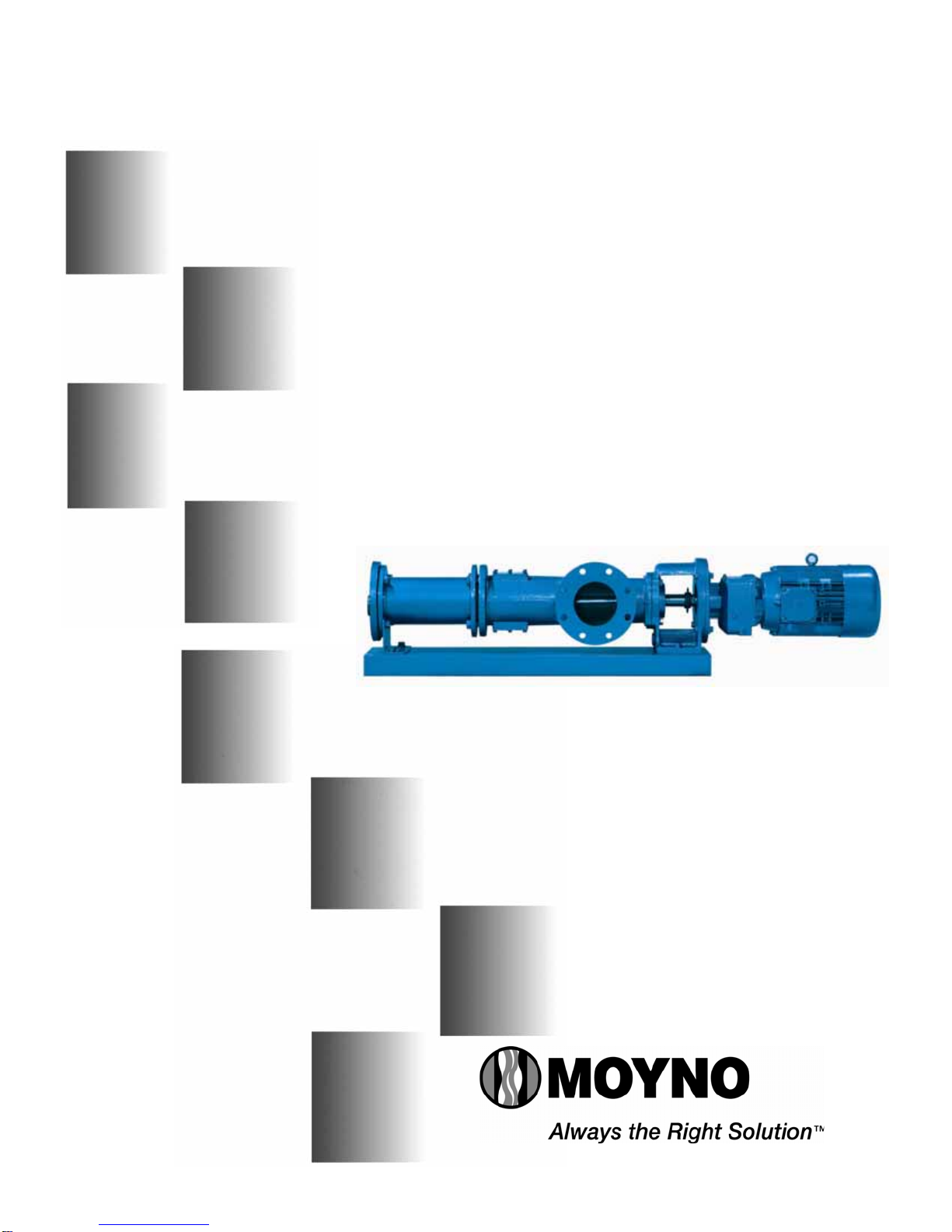
2. Use a packing puller tool (see Figure 4-2) to remove the
packing (150).
Figure 4-2. Packing Removal Tool
3. Inspect surface of drive shaft for excessive wear or grooves
due to packing rub. If shaft is worn, or is badly scored or
grooved, it should be replaced.
4. If drive shaft is not worn, install a lantern ring and four
packing rings, lubricating them before installation with a
good grade of packing grease. Be sure to stagger the
packing ring joints at 90-degree increments.
Note: The stuffing box is supplied with four rings installed, a fifth
ring may be added after initial compression.
CAUTION: ALWAYS USE A PROPER PACKING TAMPER
TOOL TO INSTALL PACKING. Do not use a pointed or sharp
tool, as damage to the packing material or drive shaft could
result. To assure proper shaft lubrication, never use a one-piece
spiral wrap packing.
5. Replace packing gland halves and secure with packing
gland and nuts (156).
Page 3
6. Adjust packing per Section 4-3.
5-1. DISASSEMBLY
Note: In this section and in following sections on CLEANING,
INSPECTION, and ASSEMBLY, the first reference to each
pump part will be followed by a number or letter in
parentheses ( ). These numbers and letters are those used to
identify the pump parts and hardware items in the Exploded
Views in Section 13-1.
5-2. DISCONNECT PUMP
1. Disconnect the power source.
2. Close suction and discharge valves to isolate the pump
from the line.
5-3. STATOR REMOVAL
1. Remove section of discharge pipe attached to discharge
flange (200).
2. Remove discharge flange by unbolting from stator clamp
ring (210) and remove stator gasket (510). Use a
screwdriver tip to remove stator retaining ring (480), stator
clamp ring (210), and pump support (220) from stator
(500).
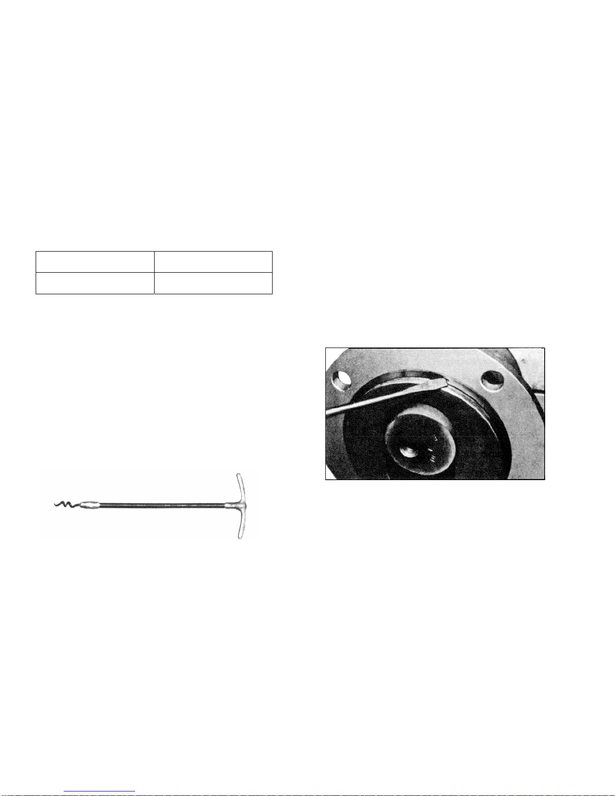
3. Unbolt stator clamp ring (210) from suction housing and
remove stator from rotor (turning stator clockwise while
removing will ease disassembly). Remove the stator
retaining ring. Remove stator clamp ring from stator. See
Figure 5-1. for the typical retaining ring removal procedure.
Figure 5-1. Typical Retaining Ring Removal
5-4. SUCTION HOUSING REMOVAL
1. Remove four bolts and lock washers (230) holding the
suction housing (100) to the drive adapter (10).
2. Pull the suction housing toward the rotor and away from
the adapter housing. Place a block of wood under the
suction housing to prevent it from dropping as you pull it
away from the adapter housing.
5-5. ROTOR/CON ROD/DRIVE SHAFT ASSEMBLY
REMOVAL
1. Slide the slinger ring (60) along the drive shaft (400),
towards the gear reducer, exposing the drive pin (70).
2. With a punch and hammer, tap the drive pin from the
drive shaft.
3. Carefully pull the rotor/con rod/drive shaft assembly from
the gear reducer. Place the assembly aside for now. On
larger sizes where it may be awkward to remove the
whole rotating unit as one piece, the rotor can be remove
first. Refer to section 5-8 for joint disassembly
instructions.

Page 4
5-6. PACKING HOUSING REMOVAL
1. Pull the packing housing (140) away from the drive adapter
(10). Remove the O-ring (530).
2. Remove the gland nuts (156), studs (155), and packing
gland halves (152).
3. Use a packing removal tool to remove two rings of packing
(150), two lantern rings (151), and the last two rings of
packing (150).
OR
5-7. SEAL HOUSING REMOVAL
1. Pull the seal housing (140) from the drive adapter (10).
Remove the O-ring (530).
2. Carefully push the stationary seal face from the adapter
housing.
3. Carefully pull the rotating portion of the mechanical seal
(150) from the drive shaft.
5-8. ROTOR, DRIVESHAFT, AND CONNECTING ROD
DISASSEMBLY
1. Remove the vent plug (440) and set screw (450) from the
gear joint shell (410).
2. Remove six socket head screws (430) from head ring (420)
and remove head ring and O-ring (540). Slide connecting
rod/gear joint assembly off rotor head. Remove gear joint
keys (360) and primary thrust plate (310) from rotor (470).
3. Slide gear joint shell (410) off gear ball/connecting rod
assembly. Slide ring gear (350) off gear ball (300).
4. Clamp connecting rod (460) in vice and hold with pipe
wrench and remove lock nut (330). Remove gear ball
(300), secondary thrust plate (320), seal support (340), and
gear joint seal (520) from connecting rod.
6. Repeat steps 2 through 5 for driveshaft joint disassembly.
NOTE: It is recommended that each time the rotor and gear
joint is disassembled, the rotor head O-ring (360) and gear joint
seal (520) should be replaced.
5-9. Drive Adapter / Gearmotor Removal. Remove the four
bolts and lock washers holding the drive adapter (10) to the
gear reducer. Pull the drive adapter from the reducer.
5-10. Cleaning. Clean parts in a suitable cleaning solvent.
6-1. INSPECTION
6-2. DRIVESHAFT AND PACKING/SEALS
1. Inspect drive shaft (400) for scoring, burrs, cracks, etc.
Replace as necessary.
2. It is sound practice to always replace O-rings and gear
joint seals.
3. It is sound practice to replace mechanical seals when the
pump is disassembled. Extreme care should be taken to
protect the seal faces from damage. These are fragile;
avoid touching the faces and keep them clean.
The rubber bellows will adhere to the shaft after
assembly and must be replaced if removed from the
shaft.
4. It is sound practice to always replace packing (150)
whenever the pump is disassembled.
6-3. ROTOR
1. To check for excessive rotor (470) wear, measure
the rotor crest-to-crest diameter (see Figure 6-1.)
and compare with the following chart:
Rotor Size Standard Crest-to-Crest
Diameter (Inches)
022
036
050
065
090
115
175
220
345
3.425
4.015
4.015
4.906
4.906
5.709
6.584
7.116
7.260
The rotor size is designated by the fourth, fifth, and sixth
numbers in the model number (i.e.,1BB065).
Figure 6-1. Measuring Rotor Diameter
2. If the measured crest-to-crest diameter is within
.010 in. of the standard value, the rotor is reusable
provided that:
a. The rotor surface is not cracked, pitted or deeply
grooved (.030 in. or more).
3. Rotors with crest-to-crest diameters greater than
.010 in. under the standard value should generally
be replaced.
6-4. Stator. The best indication of stator wear (500) and the
need for replacement is a drop in pump performance. Stators
with interior surfaces that are pitted, grooved or gouged
should also be replaced.
6-5. All Other Parts. Check for cracks, excessive wear,
damage to threaded holes, burrs, etc. Replace as necessary.
Replace O-rings (530) and both gaskets (510) at each
disassembly and reassembly.

7-1. ASSEMBLY
7-2. LUBRICATION DURING ASSEMBLY
1. Gear Joints. Both gear joints should be packed with
lubricant during assembly (Section 7-3). DO NOT use zerk
fittings to lubricate gear joints after assembly. The pipe
plugs (440) in the drive shaft head, drive shaft, and gear
joint shell are vent plugs and MUST BE REMOVED during
assembly of the gear joints to allow excess lubricant to vent
from the gear joints.
2. Packing. Lubricate packing rings during assembly.
Additional grease can be added after assembly through
zerk fittings if installed in the side of the stuffing box.
3. Approved Lubricants:
CAUTION: Do not mix different brands of lubricants for the
same application.
Area to Lubricate Approved Lubricant or
Equivalent
Gear Joints
& Packing ACG-2
(Dubois Chemical, Inc.)
7-3. DRIVESHAFT AND ROTOR GEAR JOINT
ASSEMBLY
1. Insert the primary thrust plate (310) into driveshaft/rotor
head, flat side first. Thrust plate and driveshaft/rotor head
surfaces must be flush to assure proper assembly and
operation of the pump (see Figure 7-1.).
Figure 7-1. Rotor Thrust Plate Seating Detail
2. Assemble the gear joint by first fitting a gear joint seal (520)
onto the connecting rod assembly (460). The seal must be
positioned so that the flat face of the seal neck fits into the
seal retainer component of the connecting rod assembly.
Apply a small coating of approved gear joint lubricant to the
inside surfaces of the seal.
3. Apply a small amount of lubricant to the flat face of the seal
support (340) and slide it onto the connecting rod so that
the flat face and radius of the support is against the seal
(520).
4. Grease the concave spherical surface of the rear thrust plate
(320) and position thrust plate against the seal (520) with
the lip on the outside diameter of the seal fitting the step on
the back side of the thrust plate.
5. Apply a film of grease to the splines on the inside of the
gear ball (300). Install gear ball on connecting rod (460),
with counter-bored end (end without splines) first on
connecting rod. Gear ball should slide freely against
shoulder on connecting rod. Place lock nut (330) on
connecting rod and tighten against gear ball. Apply grease
to spherical surfaces and teeth of gear ball.
Page 5
6. Apply grease to the teeth of the ring gear (350), and slide ring
gear into the gear ball. When ring gear is in place, keyways
should be facing the lock nut end of connecting rod.
7. Apply a thin coating of grease to the spherical surface of the
thrust plate (310) already installed in the driveshaft/ rotor head.
Fill the recessed area in the driveshaft/rotor head with grease.
Place keys (360) in the keyways in the ring gear.
8. Align the keys in the ring gear with the keyways in the
driveshaft/rotor head and slide assembled gear joint
components into the gear joint shell (410). Check to be sure
the keys are properly engaged in the driveshaft/rotor head
and ring gear.
9. Lightly lubricate the O-ring (540) and then position the O-
ring in outside diameter O-ring groove slot of the gear
joint head ring (420).
10.Slide the head ring (420) over the connecting rod (460), O-
ring side first, towards the assembled gear joint
components and driveshaft/rotor gear joint shell (410).
Align holes in head ring (420) with six threaded holes in
end of gear joint shell and install six stainless socket head
screws (430). Tighten the six socket head screws evenly,
checking to ensure O-ring (540) remains in place. When
tightened properly, a small gap of a few thousandths of an
inch may exist between the shell (410) and gear joint head
ring (420). Note: After assembling the first joint the gear
joint shell (410) for the second joint must be placed on the
con rod before assembly on the second joint begins.
11.Excess grease in the assembly will be purged from the
vent hole in the gear joint retainer (420) while the socket
head screws are tightened. Rotate the free end of the
connecting rod in a circular motion to assure that the joint
is free and assembled properly. This will also help to
purge excess grease from the assembly.
12.Install the stainless steel pipe plug (440) in the vent hole
in the shell and tighten.
13.Coat the rotor (470) contour with waterless hand cleaner,
glycol, or other lubricant compatible with the stator
elastomer. Insert rotor into stator. NOTE: To ease
assembly, turn the stator counter-clockwise while
assembling onto the rotor.
15.For Pump Models 065 / 090 / 115 / 175 / 220 / 345
a. Secure the pump support (220) to the suction
housing (100) with two hex head screws, lock
washers, and nuts (230/260).
16.Slide stator clamp rings (210) on both ends of the stator
(500) and secure in position with retaining rings (480).
7-4. Drive Adapter Assembly. Place the drive adapter (10)
against the flange of the gear reducer and secure with four hex
head screws and washers. Tighten evenly. Apply a liberal
amount of anti-seize lubricant to the entire surface of the
reducer shaft. Note: The drive adapter (10) must be mounted
to the baseplate before the gearbox can be mounted. For units
with a double or cartridge seal please refer to section 7-7
before mounting the gearbox to the drive adapter.
7-5. PUMPS WITH SINGLE MECHANICAL SEAL
1. Carefully slide the rotating portion of the mechanical seal
(150) onto the drive shaft up against the set collar (160).
The seal face should be facing out, away from the
connecting rod (460). Apply a small amount of grease to
the ID of the rubber bellows making it easier to slide onto
the shaft.

Page 6
2. Gently push the stationary portion of the mechanical seal
into the recess in the seal housing (140). Place the O-ring
(530) on the shoulder of the seal housing.
3. Slide the seal housing into the drive adaptor (10).
Secure the suction housing (100) to the drive adapter (10)
with four hex head screws and lock washers (20/30). Take
care to be sure the o-ring (530) is placed on the seal
housing (140) before assembling.
4. Next, carefully slide the rotating/stator assembly first
through the suction housing (100) and then through the
seal stationary face in the seal housing and over the gear
reducer shaft. Align the holes by rotating the motor fan.
Use a punch to align the holes axially being careful not to
damage the mechanical seal.
5. Replace the drive pin (70) and slide the slinger ring (60)
onto the shaft over the drive pin (70)
OR
7-6. PUMPS WITH COMPRESSION PACKING
1. The standard packing set (150) consists of four braided
packing rings. The lantern ring (151) must be ordered
separately.
2. Wipe a film of lubricant on each packing ring and install two
rings in the packing housing (140). Push each ring firmly in
place, staggering the splits in each ring 90 degrees.
3. Install the lantern ring and the last two rings of packing,
staggering the splits as before.
4. Install packing gland studs (155), packing gland halves
(152), and gland nuts (156). Tighten nuts finger tight at this
point. Place the O-ring (530) on the shoulder of the packing
housing.
5. Slide the packing housing into the drive adaptor (10).
Secure the suction housing (100) to the drive adapter (10)
with four hex head screws and lock washers (20/30). Take
care to be sure the o-ring (530) is placed on the seal
housing (140) before assembling.
6. Next, carefully slide the rotating/stator assembly first
through the suction housing (100) and then through the
seal stationary face in the seal housing and over the gear
reducer shaft. Align the holes by rotating the motor fan.
Use a punch to align the holes axially.
7. Replace the drive pin (70) and slide the slinger ring (60)
onto the shaft over the drive pin (70).
OR
7.7. PUMPS WITH DOUBLE OR CARTRIDGE
MECHANICAL SEALS
1. Apply a small amount of grease to the ID of the rubber
bellows or o-rings making it easier to slide onto the shaft.
2. Gently push the stationary portion of the mechanical seal
into the recess in the seal housing and housing plate (140)
(Cartridge seals are self contained.) Insert rotating seal
assemblies in to the seal housing and bolt cover plate to
the housing with four cap head screws. Place the O-ring
(530) on the shoulder of the seal housing.
3. Hold the seal housing (150) in the drive adaptor (10).
Secure the gearmotor to the drive adapter with four bolts.
Gently rest the seal on the gearbox shaft. Secure the
suction housing (100) to the drive adapter (10) with four
hex head screws and lock washers (20/30). Take care to
be sure the o-ring (530) is placed on the seal housing
(140) before assembling.
4. Next, carefully slide the rotating/stator assembly first
through the suction housing (100) and then through the
seal stationary face in the seal housing and over the
gear reducer shaft. Align the holes by rotating the motor
fan. Use a punch to align the holes axially being careful
not to damage the mechanical seal.
5. Replace the drive pin (70) and slide the slinger ring (60)
onto the shaft over the drive pin (70)
7-8. SUCTION HOUSING/STATOR ASSEMBLY
1. Bolt stator clamp ring (210) to the suction housing (100)
with six hex head screws and lock washers (230/260).
2. Bolt stator clamp ring (210) to the discharge flange (200)
with six hex head screws and lock washers (230/260).
7-9. PUMP CONNECTIONS
1. Connect suction and discharge piping to the pump. Check
INSTALLATION instructions in Sections 2-1. through 2-6.
2. Review OPERATION instructions in Sections 3-1.
through 3-4. before starting the pump.
8-1. STORAGE
Short-Term Storage. Storage of six months or less will not
damage the pump. However, to ensure the best possible
protection, the following is advised:
1. Store pump inside whenever possible or cover with
some type of protective covering. Do not allow moisture
to collect around pump.
2. Remove drain plug to allow the pump body to drain and
dry completely.
3. See drive manufacturer’s instructions for motor and/or
drive storage.
4. See OPERATION, Sections 3-1. through 3-4., before
startup. Be sure all lubricants are in good condition.
Long-Term Storage. If pump is to be in storage for more
than six months, perform the above short-term storage
procedures with the exception of Step 4. In its place it is
suggested that the stator be removed to avoid developing a
“set” condition. In addition: Apply rust inhibitor to all
unpainted cast iron and machined carbon steel surfaces.
9-1. RECOMMENDED SPARE PARTS
Your Moyno 2000 pump has been designed and built to
minimize overall operating cost. All wearable parts are
replaceable. A recommended inventory of spare parts is
dependent upon the application and the importance of
continued operation.
To minimize downtime, we recommend the following spare
parts be in your inventory: This is a suggested list. For further
assistance, contact your Moyno representative.
(1) Rotor
(1) Stator
(2) Stator Gaskets
(1) Con Rod
(1) Mechanical Seal / Packing
(2) Gear Joint Kits

Page 7
10-1. HARDWARE LIST – BB022 THRU BA175
Ref
No. Description BB022 BB036 BB050 BB065 BB090 BB115 BA175
20 Hex Screw-200mm M10 X 50
30 Lock Washer M10
40 Hex Nut M10 X 1.5
20 Hex Screw-250mm
30 Lock Washer
40 Hex Nut
20 Hex Screw-300mm
30 Lock Washer
40 Hex Nut
20 Hex Screw-350mm
30 Lock Washer
40 Hex Nut
20 Hex Screw-450mm
30 Lock Washer
40 Hex Nut
50 Pipe Plug
110 Hex Screw
120 Lock Washer
130 Pipe Plug
153 Socket Pipe Plug
154 Grease Fitting
155 Gland Stud-Small Shaft
155 Gland Stud-Large Shaft
156 Hex Nut-Small Shaft
156 Hex Nut-Large Shaft
170 Socket Pipe Plug
235 Hex Screw
236 Lock Washer
237 Hex Nut
240 Hex Screw M20 x 50 M20 x 60
245 Lock Washer M20 x 50
250 Hex Screw M16 x 40
255 Hex Screw
260 Lock Washer
430 Socket Screw
440 Socket Pipe Plug
450 Set Screw
M16 x 50
M12
M20 x 55
5/16-18 x .625"
M8 x 1.25 x 50 M10 x 1.5 x 60
#10-24 x .50" 1/4-20 x .625"
1/4-17 NPT
M16
M16 x 45
M20 x 50
M20 x 45
M20 x 55
M10 x 1.5
1/4-18 NPT M12 x 50
M20
M8 x 1.25 M10 x 1.5 x 60 M10 x 1.5
M20 x 55
M12 x 1.75
1/4-27 NPT
M16
M12 x 65
M12
M12 x 1.75
M16 x 70
M16
M16 x 2.0
M12 x 60
M12
M12 x 1.75
3/4" NPT
M20
1" NPT
1/4-27 NPT
3/4-10 x 1.75"
3/4-10 x 2.25"
3/4"

Page 8
10-2. HARDWARE LIST – BA220 THRU BC345
Ref No. Description BA220 BB175 BB220 BB345 BC175 BC220 BC345
20 Hex Screw-200mm
30 Lock Washer
40 Hex Nut
20 Hex Screw-250mm M12 x 60
30 Lock Washer M12
40 Hex Nut M12 x 1.75
20 Hex Screw-300mm
30 Lock Washer
40 Hex Nut
20 Hex Screw-350mm
30 Lock Washer
40 Hex Nut
20 Hex Screw-450mm
30 Lock Washer
40 Hex Nut
50 Pipe Plug
110 Hex Screw M20 x 55
120 Lock Washer
130 Pipe Plug
153 Socket Pipe Plug
154 Grease Fitting
155 Gland Stud-Small Shaft M10 x 1.5 x 60
155 Gland Stud-Large Shaft M10 x 1.5 x 60
156 Hex Nut-Small Shaft M10 x 1.5
156 Hex Nut-Large Shaft M10 x 1.5
170 Socket Pipe Plug
235 Hex Screw
236 Lock Washer
237 Hex Nut
240 Hex Screw
245 Lock Washer
250 Hex Screw
255 Hex Screw
260 Lock Washer
430 Socket Screw
440 Socket Pipe Plug
450 Set Screw
M12
M16
M16 x 2.0
M20 x 60
3/4" NPT
1/4-17 NPT
5/16-18 x .625"
M12 x 1.75 x 70
1/4-20 x .625"
M12 x 1.75
1/4-18 NPT M12 x 50
M12 x 1.75
M12 x 1.75 x 70
M12 x 1.75
M16 x 70
M12 x 1.75
M20 x 60
1/4-27 NPT
M16 x 55
M16
M16 x 2.0
M12 x 65
M12
M20
1" NPT
1/4-27 NPT
M20
3/4-10 x 1.75"
3/4-10 x 2.25"
3/4"

Page 9
11-1. PARTS LIST – BB022 THRU BA175
Ref
No. Description BB022 BB036 BB050 BB065 BB090 BB115 BA175
10 Drive Adapter -200mm
10 Drive Adapter-250mm
10 Drive Adapter-300mm
10 Drive Adapter-350mm
10 Drive Adapter-450mm
60 Slinger Ring-Small Shaft
60 Slinger Ring-Large Shaft
70 Drive Pin
100 Suction Housing-ANSI 4251750201 4251752001
100 Suction Housing-Metric 4251750301 4251752201
140 Packing Housing-Small Shaft
140 Packing Housing-Large Shaft
150 Packing Set-Small Shaft
150 Packing Set-Large Shaft
151 Lantern Ring-Small Shaft
151 Lantern Ring-Large Shaft
152 Packing Gland Half-Small Shaft
152 Packing Gland Half-Large Shaft
140 Seal Housing
140 Seal Housing
150 Mechanical Seal -2100-Small Shaft
150 Mechanical Seal -2100-Large Shaft
150 Mechanical Seal-MG12-Small Shaft
150 Mechanical Seal-MG12-Large Shaft
160 Shaft Collar-Small Shaft
160 Shaft Collar-Large Shaft
200 Discharge Flange-ANSI 4240428001 4103001501
200 Discharge Flange-Metric 4241044001 4241311001
210 Clamp Ring AG0933 4103001400
220 Pump Support 4063001100
220 Pump Support-2 stage 4063001100
230 Pump Support
230 Pump Support-2 stage
300 Gear Ball
310 Thrust Plate
320 Thrust Plate
330 Lock Nut
340 Seal Support
350 Ring Gear
360 Key
400 Dive Shaft-Plate-Small Shaft
400 Drive Shaft-Non Plate-Small Shaft
400 Dive Shaft-Plate-Large Shaft
400 Drive Shaft-Non Plate-Large Shaft
410 Gear Joint Shell
420 Head Ring
460 Connecting Rod 4230099008 4230987008
470 Rotor - TS - 1 stage C71EF1 C71EG1 C71E51 C71FH1 C71F91 C71GJ1 4251479007
470 Rotor - 316ss - 1 stage C81EF1 C81EG1 C81E51 C81FH1 C81F91 C81GJ1
470 Rotor - TS - 2 stage C72EF1 C72EG1 C72E51 C72FH1 C72F91 C72GJ1
470 Rotor - 316ss - 2 stage C82EF1 C82EG1 C82E51 C82FH1 C82F91 C82GJ1
480 Retaining Ring AF0085 AK0084
500 Stator - 1 Stage C310FQ C310GQ C3150Q C310HQ C3190Q C310JQ C310KQ
500 Stator - 2 stage C320FQ C320GQ C3250Q C320HQ C3290Q C320JQ
510 Stator Gasket BF085Q BK085Q
520 Gear Joint Seal
530 O-ring
540 O-ring
Note: For Ref Nos. 500 - 540 the Q in the designation represents Nitrile (Buna N), The Q in part number is substituted with an B for EPDM or F for Flouroelastomer(Viton)
4252016118
4252016018
RG0761
AG0952
4241295001
4241302001
AG0951
4241749080
4241750060
4241750080
4230990015
4230991015
4230530000
4230531000
4220802017
4251672001
4251066001
3403654004
3403654005
4230531000
4230532000
4251751001
4251751101
4251093003
4251093001 4251843003
4251843001
4251843002
4220796017
4251671001
4251084001
4251750001
4251750101
3403654003
3403654004
4230482003
4230482004
4240927007
4240928007
4252056007
4252057007
4230989015
4230990015
4073000901
4241749045
4241749060
4241750045
4241750060
4241046001
AG0932
4241301001-1
4241301001-2
6191760501-4
6191760501-2
AE0951
PE0981
4241718001
PE0982
RE0581
PE0891
AE0952
RE0761
AG0085
4252012015
4252012115
4252013015
4252013115
PE0911
PE034D
4230983008
BG085Q
PE087Q
TH211Q
PE113Q
4252059007
4241749060
RF0761
PF0982
4083000901
RG0581
PG0982
PG0981
PG0891
4230482005
4240928007
4240929007
4252058007
PF0981
AF0951
4241291001
PF113Q
PG087Q
J10111
PG034D
PG0911
4252017118
4252017018
RF0581
PF0891
AF0952
4252014015
4252014115
4252015015
4252015115
PF0911
PF034D
4230571008
AH0085
BH085Q
PF087Q
4241291001
4241292001
4230170001
4083001000
4230482004

Page 10
11-2. PARTS LIST – BA220 THRU BC345
Ref
No. Description BA220 BB175 BB220 BB345 BC175 BC220 BC345
10 Drive Adapter -200mm
10 Drive Adapter-250mm 4251843003
10 Drive Adapter-300mm 4251843001
10 Drive Adapter-350mm 4251843002
10 Drive Adapter-450mm
60 Slinger Ring-Small Shaft 4230531000 4230663000
60 Slinger Ring-Large Shaft 4230532000
70 Drive Pin 4220796017
100 Suction Housing-ANSI 4251752001
100 Suction Housing-Metric 4251752201
140 Packing Housing-Small Shaft 4251672001 4251086001
140 Packing Housing-Large Shaft 4251066001
150 Packing Set-Small Shaft 3403654004 3403654006
150 Packing Set-Large Shaft 3403654005
151 Lantern Ring-Small Shaft 4230482004 4230482006
151 Lantern Ring-Large Shaft 4230482005
152 Packing Gland Half-Small Shaft 4240928007 4240931007
152 Packing Gland Half-Large Shaft 4240929007
140 Seal Housing 4252058007 4252061007
140 Seal Housing 4252059007
150 Mechanical Seal -2100-Small Shaft 4241749060 4241749100
150 Mechanical Seal -2100-Large Shaft 4241749080
150 Mechanical Seal-MG12-Small Shaft 4241750060 4241750100
150 Mechanical Seal-MG12-Large Shaft 4241750080
160 Shaft Collar-Small Shaft 4230990015 4230992015
160 Shaft Collar-Large Shaft 4230991015
200 Discharge Flange-ANSI
200 Discharge Flange-Metric
210 Clamp Ring
220 Pump Support 4241295001 4241296001
220 Pump Support-2 stage
230 Pump Support 4241302001 4241303001
230 Pump Support-2 stage
300 Gear Ball AG0951
310 Thrust Plate PG0981
320 Thrust Plate PG0982
330 Lock Nut RG0581
340 Seal Support PG0891
350 Ring Gear AG0952
360 Key RG0761
400 Dive Shaft-Plate-Small Shaft 4252016018 4252019018
400 Drive Shaft-Non Plate-Small Shaft 4252016118 4252019118
400 Dive Shaft-Plate-Large Shaft 4252017018
400 Drive Shaft-Non Plate-Large Shaft 4252017118
410 Gear Joint Shell PG0911
420 Head Ring PG034D
460 Connecting Rod 4230987008
470 Rotor - TS - 1 stage 4252006007 C71HK1 4252008007 4252024007 C71HK1 4252008007 4252024007
470 Rotor - 316ss - 1 stage C81HK1 C81HK1
470 Rotor - TS - 2 stage C72HK1 4252010007 C72HK1 4252010007
470 Rotor - 316ss - 2 stage C82HK1 C82HK1
480 Retaining Ring
500 Stator - 1 Stage 4241056101 C310KQ 4241056101 C3145Q C310KQ 4241056101 C3145Q
500 Stator - 2 stage C320KQ 4241056102 C320KQ 4241056102
510 Stator Gasket
520 Gear Joint Seal PG087Q
530 O-ring J10111
540 O-ring PF113Q
Note: For Ref Nos. 500 - 540 the Q in the designation represents Nitrile (Buna N), The Q in part number is substituted with an B for EPDM or F for Flouroelastomer(Viton)
4241749100
4241295001
4240931007 4252062007
4241749080
4252061007
4252060007
4241759120
4230482005
4240930007
4230482007
3403654007
4230482006
4240929007
4251752301
4251086001
3403654005
3403654006
AK0084
BK085Q
4103001501
4251039001 4251069001
4220493017
4252021001 4251083001
4052006002
4230664000
3207902266
3207902158
PH087Q
PH034D
4230985008
4230532000
4230663000
4241311001
4103001400
4251039002
PH0982
AH0951
PH0981
4230992015
4241302001
4220642017
4251752101
RH0581
4252018118
4252019018
4252019118
4252020018
PH0891
AH0952
RH0761
PH0911
4252020118
4241750080
4241750100
4230991015
4241759120
6100470030
4241296001
4241303001
4252018018

Page 11

Page 12
13-1. SEAL SET DIMENSIONS

Page 13
14-1. TROUBLESHOOTING CHART

©2005 by Moyno, Inc. Printed in U.S.A.
®Moyno is a registered trademark of Moyno, Inc.
Your Authorized Service Distributor is:
Other manuals for 2000 CC
1
Table of contents
Other moyno Water Pump manuals
Popular Water Pump manuals by other brands

Wesco
Wesco 272397 Operating instructions and parts manual

Little Giant
Little Giant CP1 Series manual

Euro garden
Euro garden ES-DP 5225 N Original operating instructions

Little Giant
Little Giant 15SC-CIA-RF owner's manual

Pro Work
Pro Work PHW 3600 operating instructions

WAGNER
WAGNER EvoMotion 20-30 operating manual