MPS EVKT-MACOM User manual

EVKT-MACOM
MagAlpha Communication Kit
EVKT-MACOM www.MonolithicPower.com 1
3/1/2018 MPS Proprietary Information. Patent Protected. Unauthorized Photocopy and Duplication Prohibited.
© 2018 MPS. All Rights Reserved.
DESCRIPTION
The EVKT-MACOM is a communication kit for
the MagAlpha magnetic position sensor family.
The EVKT-MACOM offers a seamless
connection and operation with MagAlpha test
boards (TBMA) and evaluation kits (EVKT-
KNOB). The kit contains a microcontroller
motherboard, a collection of daughter boards
adapted to different sensor boards and the
related cables.
FEATURES
USB 2.0 Hi-Speed Interface
LPC4370, ARM Cortex-M4 microcontroller from
NXP
Connector board to interface with TBMA test
boards (TBMA-CONN)
Connector board to interface with EVMA test
kits (EVMA-CONN)
Compatible with Macom Application Software
(MACOM App)
APPLICATIONS
Sensor test and evaluation
Performance characterization
Production configuration and test
All MPS parts arelead-free, halogen-free, and adhere to the RoHS directive. For
MPS greenstatus, please visit the MPS website underQualityAssurance. “MPS”
and “The Future of Analog IC Technology” are registered trademarksofMonolithic
Power Systems, Inc.
OVERVIEW
Figure 1: EVKT-MACOM with EVMA-CONN daughter board

EVKT-MACOM–MAGALPHA COMMUNICATION KIT
EVKT-MACOM www.MonolithicPower.com 2
3/1/2018 MPS Proprietary Information. Patent Protected. Unauthorized Photocopy and Duplication Prohibited.
© 2018 MPS. All Rights Reserved.
Kit content
Figure 2: Kit Contents
1. 1x LPC-Link2 board with LPC4370 microcontroller from NXP
2. 1x TBMA-CONN board (LPC-Link2 daughterboard)
3. 1x EVMA-CONN board (LPC-Link2 daughterboard)
4. 1x USB cable (Type A to Type Mini-B)
5. 1x 16 conductors ribbon cable
6. 2x 8 conductors ribbon cable
7. 2x Würth Elektronik female SMT WR-MM 8 pin Connector (690367280876) for the TBMA
1
2
3
4
5
6
7
TBMA-CONN
CN1
CN2
EVMA-CONN
CN1
LPC-Link 2
NXP
EVKT-MACOM–MAGALPHA COMMUNICATION KIT
EVKT-MACOM www.MonolithicPower.com 3
3/1/2018 MPS Proprietary Information. Patent Protected. Unauthorized Photocopy and Duplication Prohibited.
© 2018 MPS. All Rights Reserved.
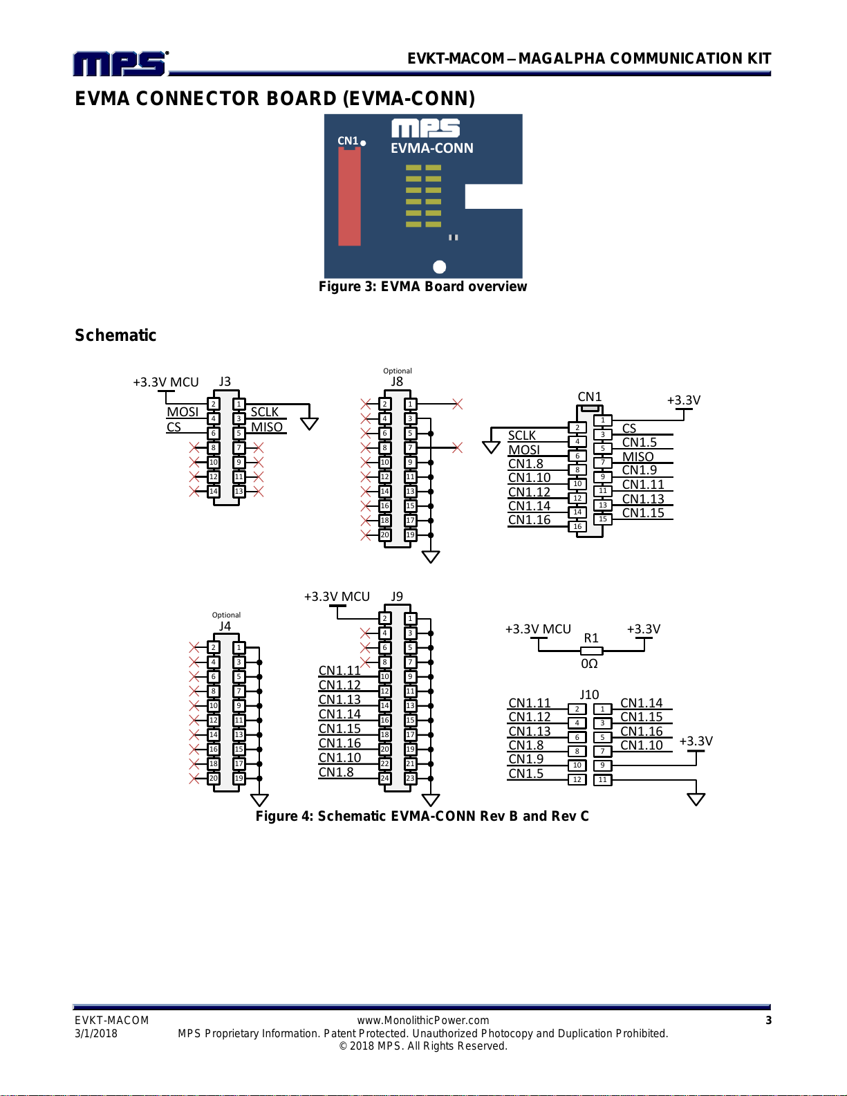
EVMA CONNECTOR BOARD (EVMA-CONN)
Figure 3: EVMA Board overview
Schematic
Figure 4: Schematic EVMA-CONN Rev B and Rev C
EVMA-CONN
CN1
CN1.10
CN1.14
CN1.16
MOSI
CN1.12
CN1
2
4
6
8
10
12
14
16
1
3
5
7
9
11
13
15
CN1.8
SCLK CS
CN1.5
MISO
CN1.11
CN1.13
CN1.15
1
2
34
56
78
910
1112
13
1516
14
1718
1920
1
2
34
56
78
910
1112
13
1516
14
1718
1920
2122
2324
CN1.12
CN1.13
CN1.11
CN1.8
CN1.10
CN1.16
CN1.15
CN1.14
1
2
34
56
78
9
MOSI
10
1112
1314
SCLK
CS MISO
1
2
34
56
78
910
1112
13
1516
14
1718
1920
J3 J8
J4
J9
R1 +3.3V+3.3V MCU
Optional
Optional
CN1.5
CN1.13
CN1.8
CN1.12
+3.3V MCU
+3.3V MCU
CN1.11
CN1.9
CN1.16
CN1.10
CN1.15
CN1.14
2
4
6
8
10
12
1
3
5
7
9
11
+3.3V
J10
CN1.9
0Ω
+3.3V
EVKT-MACOM–MAGALPHA COMMUNICATION KIT
EVKT-MACOM www.MonolithicPower.com 4
3/1/2018 MPS Proprietary Information. Patent Protected. Unauthorized Photocopy and Duplication Prohibited.
© 2018 MPS. All Rights Reserved.
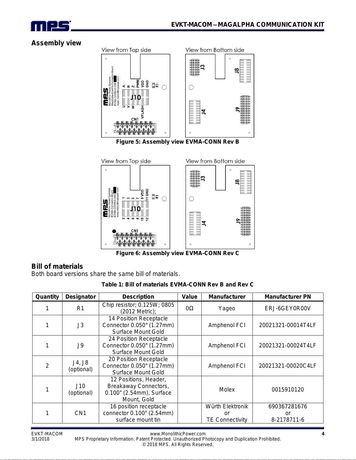
Assembly view
Figure 5: Assembly view EVMA-CONN Rev B
Figure 6: Assembly view EVMA-CONN Rev C
Bill of materials
Both board versions share the same bill of materials.
Table 1: Bill of materials EVMA-CONN Rev B and Rev C
Quantity
Designator
Description
Value
Manufacturer
Manufacturer PN
1
R1
Chip resistor; 0.125W; 0805
(2012 Metric);
0Ω
Yageo
ERJ-6GEY0R00V
1
J3
14 Position Receptacle
Connector 0.050" (1.27mm)
Surface Mount Gold
Amphenol FCI
20021321-00014T4LF
1
J9
24 Position Receptacle
Connector 0.050" (1.27mm)
Surface Mount Gold
Amphenol FCI
20021321-00024T4LF
2
J4, J8
(optional)
20 Position Receptacle
Connector 0.050" (1.27mm)
Surface Mount Gold
Amphenol FCI
20021321-00020C4LF
1
J10
(optional)
12 Positions, Header,
Breakaway Connectors,
0.100" (2.54mm), Surface
Mount, Gold
Molex
0015910120
1
CN1
16 position receptacle
connector 0.100" (2.54mm)
surface mount tin
Würth Elektronik
or
TE Connectivity
690367281676
or
8-2178711-6

EVKT-MACOM–MAGALPHA COMMUNICATION KIT
EVKT-MACOM www.MonolithicPower.com 5
3/1/2018 MPS Proprietary Information. Patent Protected. Unauthorized Photocopy and Duplication Prohibited.
© 2018 MPS. All Rights Reserved.
Connector pinout
Refer to EVKT-KNOB user guide for CN1 pin mapping.

EVKT-MACOM–MAGALPHA COMMUNICATION KIT
EVKT-MACOM www.MonolithicPower.com 6
3/1/2018 MPS Proprietary Information. Patent Protected. Unauthorized Photocopy and Duplication Prohibited.
© 2018 MPS. All Rights Reserved.
TBMA CONNECTOR BOARD (TBMA-CONN)
Figure 7: TBMA Board overview
See board schematics below (according to board marking, you may refer to schematic Rev B or Rev
C).
Schematic Rev B
Figure 8: Schematic TBMA-CONN Rev B
TBMA-CONN
CN1
CN2
1
2
34
56
78
910
1112
13
1516
14
1718
1920
1
2
34
56
78
910
1112
13
1516
14
1718
1920
2122
2324
CN2.2
CN2.3
CN2.1
CN1.8
CN2.8
CN2.6
CN2.5
CN2.4
1
2
34
56
78
9
MOSI
10
1112
1314
SCLK
CS MISO
1
2
34
56
78
910
1112
13
1516
14
1718
1920
J3 J8
J4
J9
Optional
Optional
CN2.7
CN2.3
CN1.8
CN2.2
+3.3V MCU
+3.3V MCU
CN2.1
CN1.3
CN2.6
CN2.8
CN2.5
CN2.4
2
4
6
8
10
12
1
3
5
7
9
11
+3.3V
J10
MOSI
SCLK
CS
MISO
CN1
2
4
6
8
1
3
5
7
CN2
2
4
6
8
1
3
5
7
R1 +3.3V+3.3V MCU
0Ω
CN2.2
CN2.6
CN2.8
CN2.4 CN2.3
CN2.5
CN2.7
CN2.1
CN1.8
+3.3V
CN1.3

EVKT-MACOM–MAGALPHA COMMUNICATION KIT
EVKT-MACOM www.MonolithicPower.com 7
3/1/2018 MPS Proprietary Information. Patent Protected. Unauthorized Photocopy and Duplication Prohibited.
© 2018 MPS. All Rights Reserved.
Assembly view Rev B
Figure 9: Assembly TBMA-CONN Rev B
Schematic Rev C
Figure 10: Schematic TBMA-CONN Rev C
1
2
34
56
78
910
1112
13
1516
14
1718
1920
1
2
34
56
78
910
1112
13
1516
14
1718
1920
2122
2324
CN2.2
CN2.3
CN2.1
CN1.8
CN2.8
CN2.6
CN2.5
CN2.4
1
2
34
56
78
9
MOSI
10
1112
1314
SCLK
CS MISO
1
2
34
56
78
910
1112
13
1516
14
1718
1920
J3 J8
J4
J9
Optional
Optional
CN2.7
CN2.3
CN1.8
CN2.2
+3.3V MCU
+3.3V MCU
CN2.1
CN1.3
CN2.6
CN2.8
CN2.5
CN2.4
2
4
6
8
10
12
1
3
5
7
9
11
+3.3V
J10
MOSI
SCLK
CS
MISO
CN1
2
4
6
8
1
3
5
7
CN2
2
4
6
8
1
3
5
7
R1 +3.3V+3.3V MCU
0Ω
CN2.2
CN2.6
CN2.8
CN2.4 CN2.3
CN2.5
CN2.7
CN2.1
CN1.8
+3.3V
CN1.3

EVKT-MACOM–MAGALPHA COMMUNICATION KIT
EVKT-MACOM www.MonolithicPower.com 8
3/1/2018 MPS Proprietary Information. Patent Protected. Unauthorized Photocopy and Duplication Prohibited.
© 2018 MPS. All Rights Reserved.
Assembly view Rev C
Figure 11: Assembly TBMA-CONN Rev C
Bill of materials
Both board versions share the same bill of materials.
Table 2: Bill of materials TBMA-CONN Rev B and Rev C
Connector pinout
Refer to TBMA user guide for CN1 and CN2 pin mapping.
Quantity
Designator
Description
Value
Manufacturer
Manufacturer PN
1
R1
Chip resistor; 0.125W; 0805
(2012 Metric);
0Ω
Yageo
ERJ-6GEY0R00V
1
J3
14 Position Receptacle
Connector 0.050" (1.27mm)
Surface Mount Gold
Amphenol FCI
20021321-00014T4LF
1
J9
24 Position Receptacle
Connector 0.050" (1.27mm)
Surface Mount Gold
Amphenol FCI
20021321-00024T4LF
2
J4, J8
(optional)
20 Position Receptacle
Connector 0.050" (1.27mm)
Surface Mount Gold
Amphenol FCI
20021321-00020C4LF
1
J10
(optional)
12 Positions, Header,
Breakaway Connectors,
0.100" (2.54mm), Surface
Mount, Gold
Molex
0015910120
2
CN1, CN2
8 position receptacle
connector 0.100" (2.54mm)
surface mount tin
Würth Elektronik
or
TE Connectivity
690367280876
or
7-2178711-8

EVKT-MACOM–MAGALPHA COMMUNICATION KIT
EVKT-MACOM www.MonolithicPower.com 9
3/1/2018 MPS Proprietary Information. Patent Protected. Unauthorized Photocopy and Duplication Prohibited.
© 2018 MPS. All Rights Reserved.
MAGALPHA COMMUNICATION KIT SETUP
Follow the step below to setup MagAlpha Communication Kit.
1. Install Macom Application Software (Windows only)
2. Configure LPC-Link2 board in flash boot mode.
3. Plug connector board to the LPC-Link2 (EVMA-CONN or TBMA-CONN).
4. Connect daughter board to the sensor board (EVKT-KNOB or TBMA).
5. Connect LPC-Link2 to computer.
6. Start Macom App.
Install Macom Application Software
Visit the Monolithic Power Systems website at www.monolithicpower.com and go to the Position
Sensors Design Support page. The Macom App can be found on the Software section.
Configure LPC-Link2 Board In Flash Boot Mode
Plug the jumper on JP1 to configure the microcontroller in flash boot mode. In this mode, the
microcontroller will load the firmware binary stored in the flash.
Figure 12: Configure LPC-Link2 to flash boot mode
Plug Connector Board To The LPC-Link2
Plug carefully the desired connector board to the LPC-Link2 as shown on the figure below. Check that
female headers are correctly aligned with the LPC-Link2 pins before connecting the two boards
together.
Figure 13: Plug connector board to the LPC-Link2
EVKT-MACOM–MAGALPHA COMMUNICATION KIT
EVKT-MACOM www.MonolithicPower.com 10
3/1/2018 MPS Proprietary Information. Patent Protected. Unauthorized Photocopy and Duplication Prohibited.
© 2018 MPS. All Rights Reserved.
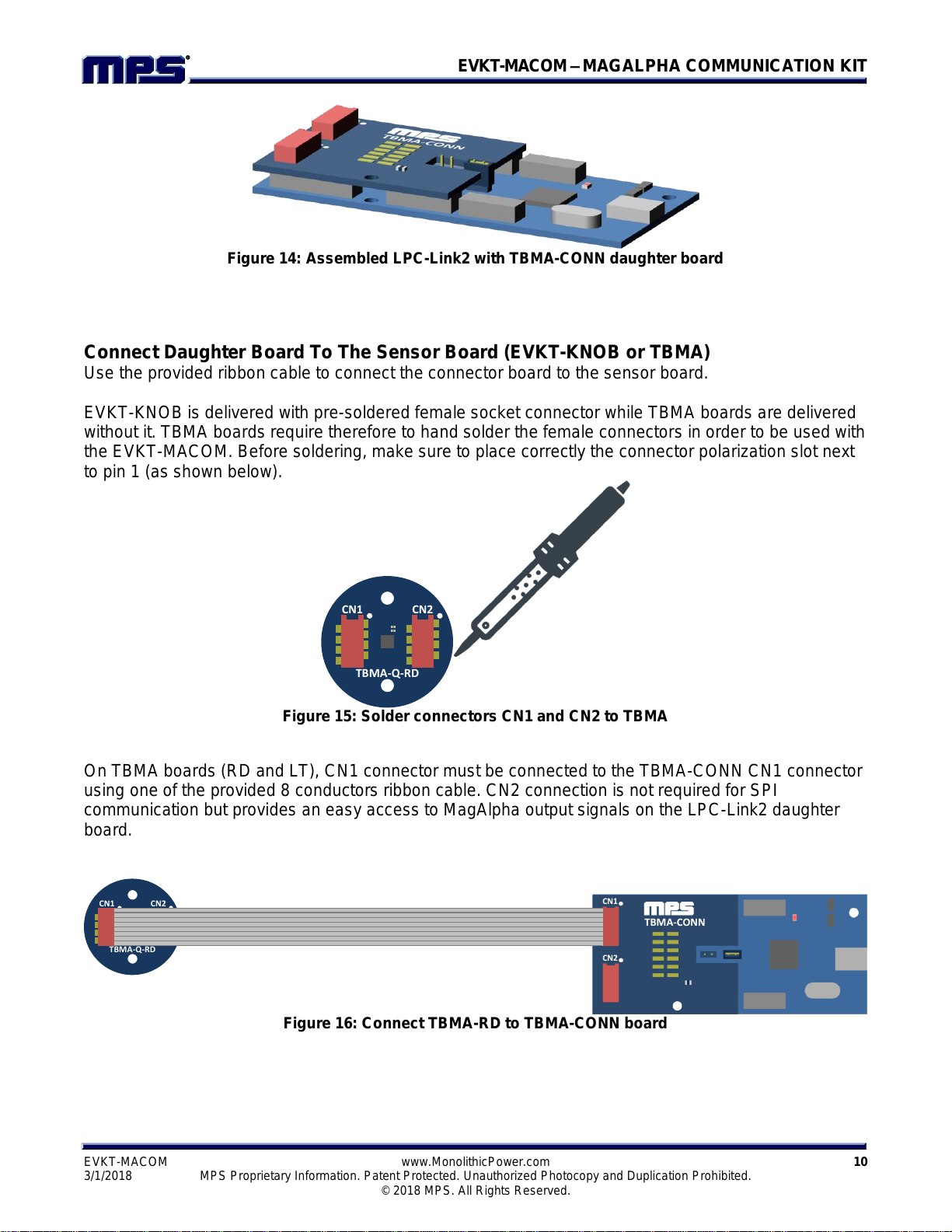
Figure 14: Assembled LPC-Link2 with TBMA-CONN daughter board
Connect Daughter Board To The Sensor Board (EVKT-KNOB or TBMA)
Use the provided ribbon cable to connect the connector board to the sensor board.
EVKT-KNOB is delivered with pre-soldered female socket connector while TBMA boards are delivered
without it. TBMA boards require therefore to hand solder the female connectors in order to be used with
the EVKT-MACOM. Before soldering, make sure to place correctly the connector polarization slot next
to pin 1 (as shown below).
Figure 15: Solder connectors CN1 and CN2 to TBMA
On TBMA boards (RD and LT), CN1 connector must be connected to the TBMA-CONN CN1 connector
using one of the provided 8 conductors ribbon cable. CN2 connection is not required for SPI
communication but provides an easy access to MagAlpha output signals on the LPC-Link2 daughter
board.
Figure 16: Connect TBMA-RD to TBMA-CONN board
CN1 CN2
TBMA-Q-RD
LPC-Link 2
NXP
TBMA-CONN
CN1
CN2
CN1 CN2
TBMA-Q-RD

EVKT-MACOM–MAGALPHA COMMUNICATION KIT
EVKT-MACOM www.MonolithicPower.com 11
3/1/2018 MPS Proprietary Information. Patent Protected. Unauthorized Photocopy and Duplication Prohibited.
© 2018 MPS. All Rights Reserved.
Figure 17: Connect TBMA-LT to TBMA-CONN board
On EVKT-KNOB, CN1 connector must be connected to EVMA-CONN CN1 connector.
Figure 18: Connect EVKT-KNOB to EVMA-CONN board (view from the top)
Figure 19: Connect EVKT-KNOB to EVMA-CONN board (view from the side)
Connect LPC-Link2 To Computer
Connect the LPC-Link2 board to the computer using the provided USB cable (Type A to Type Mini-B).
The red LED (LED1) on the LPC-Link2 should blink.
Figure 20: Connect LPC-Link2 to computer
LPC-Link 2
NXP
TBMA-CONN
CN1
CN2
TBMA-Q-LT
CN1 CN2
LPC-Link 2
NXP
EVMA-CONN
CN1
LPC-Link 2
NXP
EVMA-CONN
CN1

EVKT-MACOM–MAGALPHA COMMUNICATION KIT
EVKT-MACOM www.MonolithicPower.com 12
3/1/2018 MPS Proprietary Information. Patent Protected. Unauthorized Photocopy and Duplication Prohibited.
© 2018 MPS. All Rights Reserved.
Start Macom App
Launch the Macom App from the Start Menu. Angle data should be displayed right away.
Figure 21: Start Macom App
Figure 22: Overview of the Macom App graphical interface
EVKT-MACOM–MAGALPHA COMMUNICATION KIT
EVKT-MACOM www.MonolithicPower.com 13
3/1/2018 MPS Proprietary Information. Patent Protected. Unauthorized Photocopy and Duplication Prohibited.
© 2018 MPS. All Rights Reserved.
MACOM APP
The Macom software is a powerful and easy to use application to interact with the MagAlpha sensor
family. It provides a graphical visualization of the angle output and a convenient way to read and write
sensor parameters. In addition this App also offers the following features:
Register map overview (Read/Write sensor registers)
Import configuration script (JSON)
Export current configuration (JSON)
Save measurement data
Update EVKT-MACOM firmware (stored on LPC-Link2 Flash)
Sensor Auto Discovery (automatic detection of the available parameters and of the sensor
generation)
The Macom graphical user interface is divided in 3 areas:
The toolbar
The angle readback
The sensor parameters
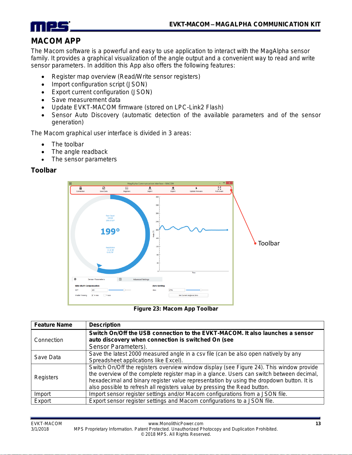
Toolbar
Figure 23: Macom App Toolbar
Toolbar
Feature Name
Description
Connection
Switch On/Off the USB connection to the EVKT-MACOM. It also launches a sensor
auto discovery when connection is switched On (see
Sensor Parameters).
Save Data
Save the latest 2000 measured angle in a csv file (can be also open natively by any
Spreadsheet applications like Excel).
Registers
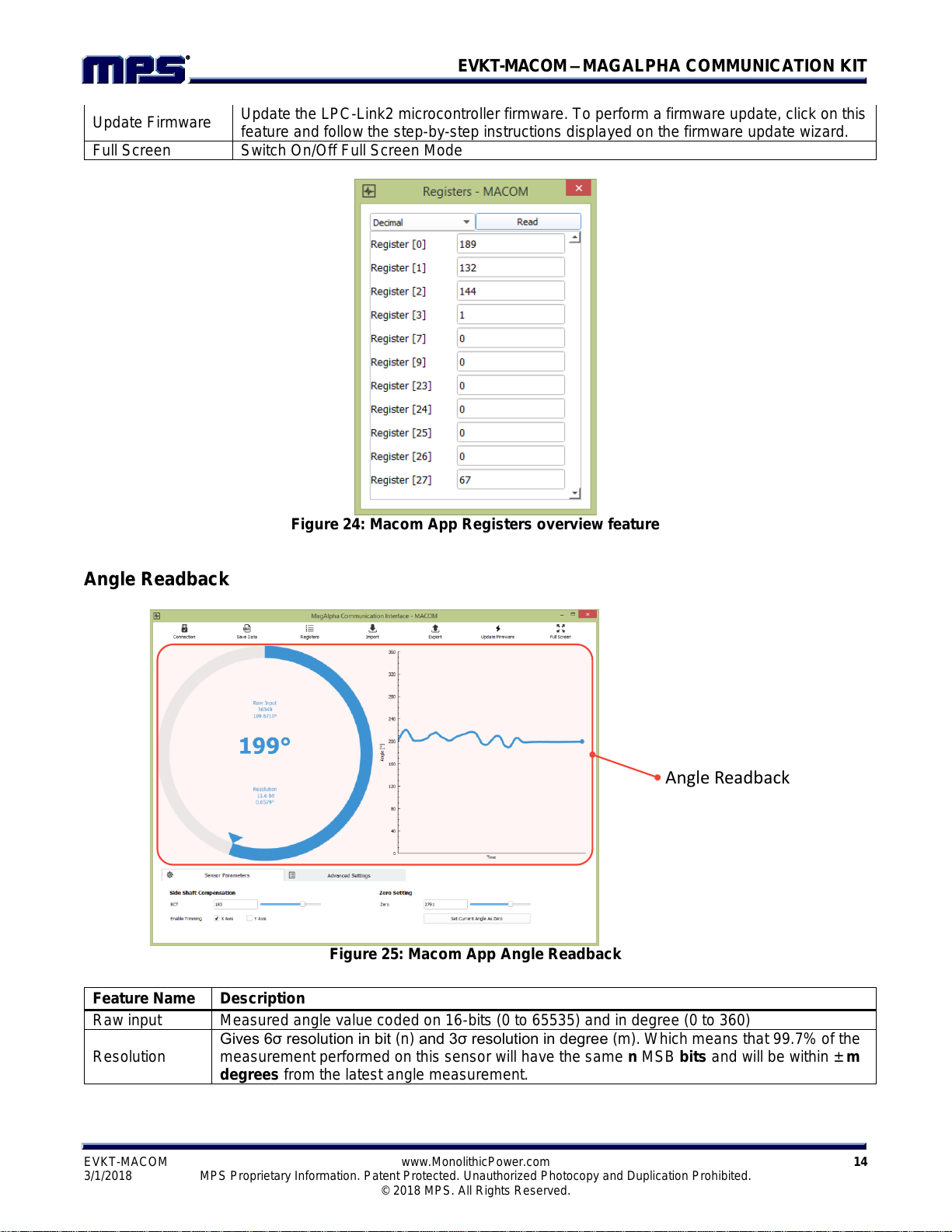
Switch On/Off the registers overview window display (see Figure 24). This window provide
the overview of the complete register map in a glance. Users can switch between decimal,
hexadecimal and binary register value representation by using the dropdown button. It is
also possible to refresh all registers value by pressing the Read button.
Import
Import sensor register settings and/or Macom configurations from a JSON file.
Export
Export sensor register settings and Macom configurations to a JSON file.
EVKT-MACOM–MAGALPHA COMMUNICATION KIT
EVKT-MACOM www.MonolithicPower.com 14
3/1/2018 MPS Proprietary Information. Patent Protected. Unauthorized Photocopy and Duplication Prohibited.
© 2018 MPS. All Rights Reserved.
Figure 24: Macom App Registers overview feature
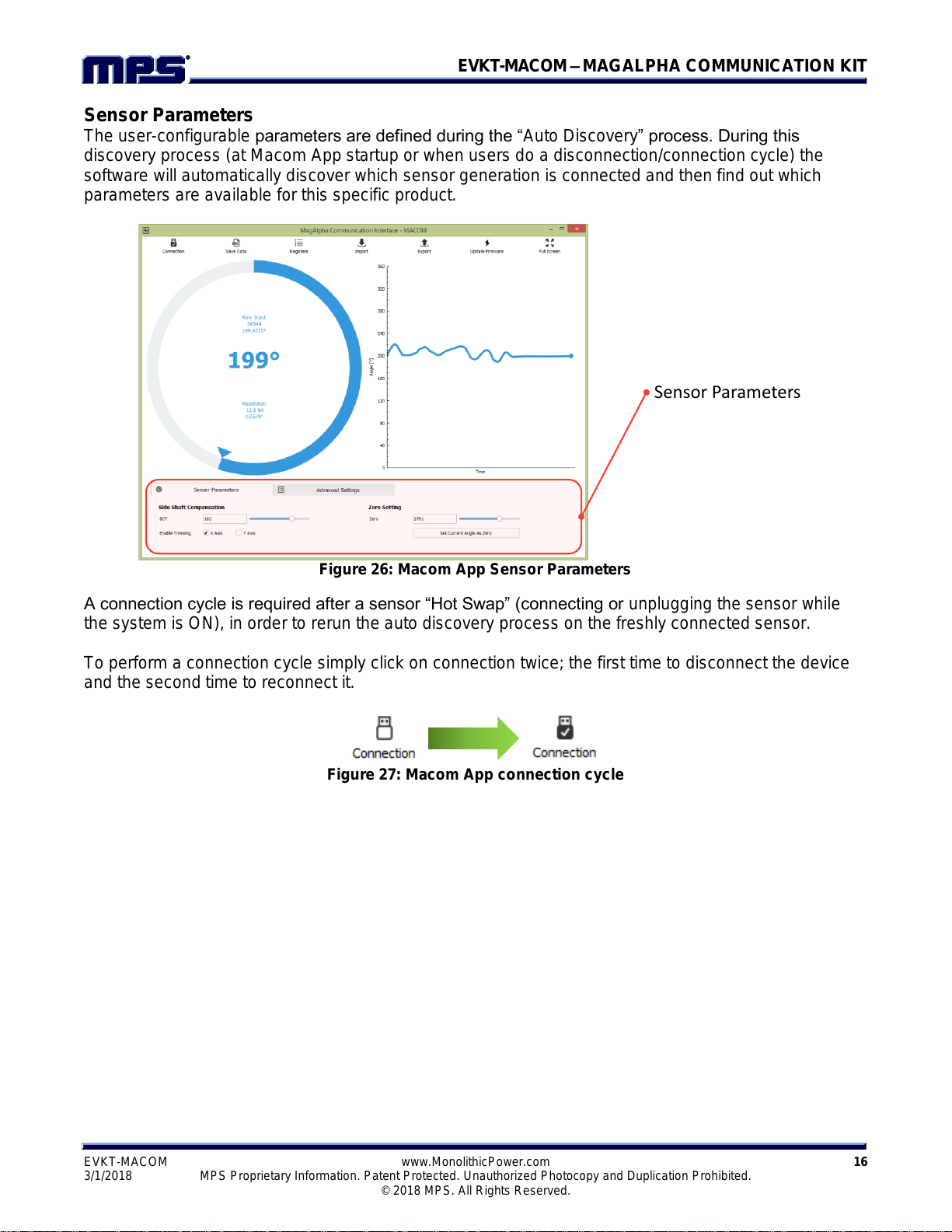
Angle Readback
Figure 25: Macom App Angle Readback
Angle Readback
Update Firmware
Update the LPC-Link2 microcontroller firmware. To perform a firmware update, click on this
feature and follow the step-by-step instructions displayed on the firmware update wizard.
Full Screen
Switch On/Off Full Screen Mode
Feature Name
Description
Raw input
Measured angle value coded on 16-bits (0 to 65535) and in degree (0 to 360)
Resolution
Gives 6σ resolution in bit (n) and 3σ resolution in degree (m). Which means that 99.7% of the
measurement performed on this sensor will have the same nMSB bits and will be within ± m
degrees from the latest angle measurement.

EVKT-MACOM–MAGALPHA COMMUNICATION KIT
EVKT-MACOM www.MonolithicPower.com 15
3/1/2018 MPS Proprietary Information. Patent Protected. Unauthorized Photocopy and Duplication Prohibited.
© 2018 MPS. All Rights Reserved.
EVKT-MACOM–MAGALPHA COMMUNICATION KIT
EVKT-MACOM www.MonolithicPower.com 16
3/1/2018 MPS Proprietary Information. Patent Protected. Unauthorized Photocopy and Duplication Prohibited.
© 2018 MPS. All Rights Reserved.
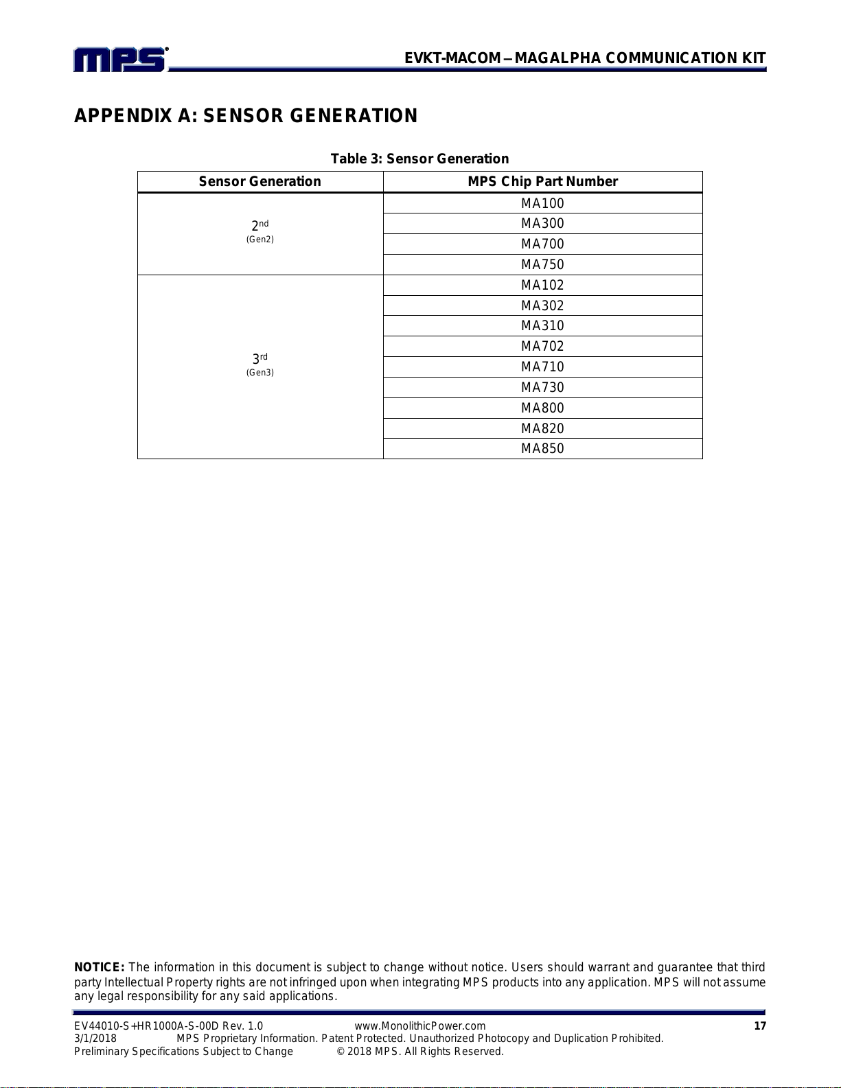
Sensor Parameters
The user-configurable parameters are defined during the “Auto Discovery” process. During this
discovery process (at Macom App startup or when users do a disconnection/connection cycle) the
software will automatically discover which sensor generation is connected and then find out which
parameters are available for this specific product.
Figure 26: Macom App Sensor Parameters
A connection cycle is required after a sensor “Hot Swap” (connecting or unplugging the sensor while
the system is ON), in order to rerun the auto discovery process on the freshly connected sensor.
To perform a connection cycle simply click on connection twice; the first time to disconnect the device
and the second time to reconnect it.
Figure 27: Macom App connection cycle
Sensor Parameters
EVKT-MACOM–MAGALPHA COMMUNICATION KIT
NOTICE: The information in this document is subject to change without notice. Users should warrant and guarantee that third
party Intellectual Property rights are not infringed upon when integrating MPS products into any application. MPS will not assume
any legal responsibility for any said applications.
EV44010-S+HR1000A-S-00D Rev. 1.0 www.MonolithicPower.com 17
3/1/2018 MPS Proprietary Information. Patent Protected. Unauthorized Photocopy and Duplication Prohibited.
Preliminary Specifications Subject to Change © 2018 MPS. All Rights Reserved.
APPENDIX A: SENSOR GENERATION
Table 3: Sensor Generation
Sensor Generation
MPS Chip Part Number
2nd
(Gen2)
MA100
MA300
MA700
MA750
3rd
(Gen3)
MA102
MA302
MA310
MA702
MA710
MA730
MA800
MA820
MA850
Other manuals for EVKT-MACOM
1
Other MPS Recording Equipment manuals


Popular Recording Equipment manuals by other brands

ALLEN & HEATH
ALLEN & HEATH AR84 Getting started guide

M-S Cash Drawer
M-S Cash Drawer EP-125KPC instructions

Inter-m
Inter-m RG-6116 Operation manual
 Interface Device NI... quick start guide")
National Instruments
National Instruments Gigabit Ethernet (GigE) Interface Device NI... quick start guide

Dangerous Music
Dangerous Music Master user guide

Vesta Fire
Vesta Fire MR-30 owner's manual


