MRC 0001634 User manual

HO Gauge EMD Modern Large
Snap-in Diesel Sound Decoder with
17 Accessory Sound Functions
Item #0001634
Thank you for purchasing our highly advanced DCC locomo-
tive sound decoder. Combined with any DCC System, our
new decoder with authentic diesel sound truly will make your
model railroad come to life.
•Replaces most locomotive circuit boards
•Synchronized diesel prime mover with randomly
associated locomotive sounds
•17 accessory functions allowing more sound control
than ever
•Programmable individual sound volumes
•1.5 amp capacity
•Programmable for either 2-digit (1-127) or 4-digit
(1-9999) addresses
•Programmable start voltage
•Programmable acceleration rate
•Programmable deceleration rate
•Programmable top voltage
•Programmable 14, 28, 128 speed steps
•Selectable factory default speed curve
•Directional lighting (FO) at 0.2 amp rate
•Programmable “Rule 17” directional lighting
•Programmable for either ditch lights, mars light, or
strobe light
•Supports advanced consisting (CV19)
•Supports programming on the main (OPS mode)
•Compatible with NMRA DCC standards
•Complies with Part 15 of FCC
•28mm speaker included
•Dimensions: 75.0mm x 17.5mm x 7.5mm
LIGHT EFFECT PROGRAMMING CHART FOR CV#112
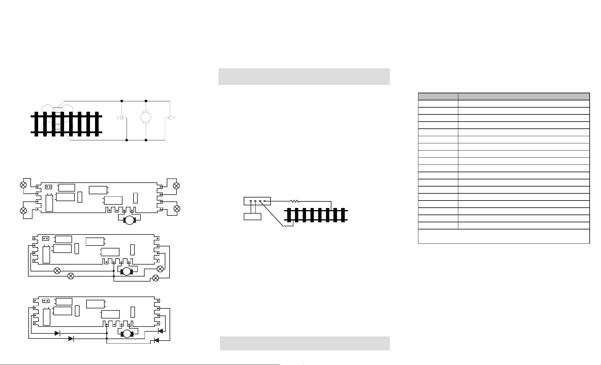
Your MRC Synchronized Diesel Sound Decoder is equipped with normal directional
lighting, plus MRC light effects. (see connect lights diagram) you can choose from
ditch lights, mars light or strobe light. Your diesel loco can also have “Rule 17”
directional headlights, through simple programming, without any complicated
wiring.
UPGRADE
This decoder can be upgraded to MRC top line decoder performance that has 8
different bell sounds and 15 different horns. if you wish to upgrade your decoder
please send in the decoder with $24.00 check.
TROUBLE SHOOTING
The MRC 0001634 HO diesel sound decoder should perform well with all DCC
systems. See your DCC system manual to learn how to program and operate the
decoder. For more information about register/CVs and their functions, please refer
to the NMRA DCC Standard & Recommended practices, RP-9.2.2 this is available
directly from the NMRA or their website at www.nmra.org.
Due to the nature of all sound decoders, the CV read back is not 100% correct. So
this feature is not supported in the decoder. This is not a defect of the decoder or
your DCC system.
Whenever the decoder doesn’t work please use program track to re-program the
loco address or program CV# 125 with value 1 to restore the decoder to factory
setting. This should bring the decoder to life.
FCC COMPLIANCE
This device complies with the part 15 of FCC rule. Operation is subject to the
following two conditions. (1) This device may not cause harmful interference, and
(2) This device must accept any interference received, including interference that
cause undesired operation.
RETURN PROCEDURE
If it should become necessary to return your decoder, unplug the decoder and
return the decoder only. Please include a letter (printed clearly) with your name,
address, a daytime telephone number, and a detailed description of the problem
you are experiencing. Please also include a $15.00 check for shipping and
handling. Be certain to return only the decoder.
Send the decoder to:
Model Rectifier Corporation
Attn: Parts & Service
80 Newfield Avenue
Edison, NJ 08837-3817 U.S.A
PROGRAMMING
This decoder supports all programming methods including: register, paged CV,
direct CV, and programming on the main (ops mode programming).
2005 MODEL RECTIFIER CORPORATION
80 NEWFIELD AVENUE
EDISON, NJ 08837-3817
NOTE: Due to limitations in older DCC systems, some of the sound functions or
light effects functions may not accessable. ALSO, you might be limited to
factory default CV values.
Printed in USA
Light CV
Ef f e ct value
CV#112 Normal on/off Normal on/off Ditch light Ditch light 0
CV#112 Normal on/off Normal on/off Mars light Single strobe light 1
CV#112 Normal on/off Normal on/off Mars light Double strobe light 2
CV #112 Rule 1 7 Rule 1 7 Ditc h light Ditc h light 16
CV#112 Rule 17 Rule 17 Mars light Single strobe light 17
CV#112 Rule 17 Rule 17 Mars light Double strobe light 18
Acc2 lightAcc1 lightHead Light Head Light
CV Register Description Range Default
CV1 R1 Short address 1-127 3
CV2 R2 Start voltage 0-32 0
CV3 R3 Acceleration 0-32 0
CV4 R4 Deceleration 0-32 0
CV5 --- Top voltage 0-32 32
--- R6 Page number --- ---
CV29 R5 Basic configuration --- 2
CV7 R7 Manufacturer version number --- 32
CV8 R8 Manufacturer ID --- 143
CV17 --- Long address upper byte 192-231 192
CV18 --- Long address lower byte 0-255 3
CV19 --- Advanced consist address 0-127 0
CV49 Sound on/off (1 =on) 0-1 1
CV51 --- Horn volume 0-3 3
CV53 --- Bell volum e 0-3 3
CV54 --- Bell ring rate 0-50 3
CV55 --- Diesel rumble volum e 0-3 3
CV56 --- Brake squeal volume 0-3 3
CV57 --- Dynamic brake volume 0-3 3
CV58 --- Air release volume 0-3 3
CV59 --- Air pum p volum e 0-3 3
CV60 --- Safety pop valve volume 0-3 3
CV61 --- Engine cooling fan volume 0-3 3
CV62 --- Coupling volum e 0-3 3
CV63 --- Random noise volume 0-3 3
CV64 --- Rail wheel clack 0-3 3
CV105 --- User identification number 0-255 0
CV106 --- User identification number 0-255 0
CV112 --- Light effects see chart 0
CV113 --- Ditch light rate 0--20 3
CV114 --- Light brightness (green, brown) 0-12 3
CV115 --- Auto brake squeal enable/disable 0-1 1(enable)
CV116 --- Coupling sound type 0-2, 2=off 1
CV117 --- Lights enable/disable 0-1 1(enable)
CV119 Coupling fire volume 0-3 3
CV120 Brake release volume 0-3 3
CV121 random noise enable 0-1 1(enable)
CV122
D ies el s ou nd typ e (0=off, 1 =rp m &
notch synchro to speed, 2=linear rpm
synchro to speed, 3=notch up/down
(F8=notch down, F9=notch up))
0-3 1
CV124
Speed curve select (0=linear, 1=slow
increase at slow speed, 2=fast
increase at slow speed
0-2 0
CV125 --- Factory default setting: Programming to 1
will restoreallCV'stodefaultsetting
---0
CV21--0
When CV21=0,allaccessoryfunctionswill
follow its ow n address. When CV 21=1, all
functionswill followtheconsistaddress
---

INSTALLATION
It is quite a challenge to install a decoder into a loco. You should have some basic
electrical knowledge and soldering skills. If you do not have the above require-
ments, please ask the dealer for help in installation.
Figure 1 shows the electrical circuit of most standard locos. The terminals of the
motor and light(s) are directly connected to the wheel pickup. Each type of loco
has its own method of electrical pickup and distribution. The connection between
the wheels, motor and light(s) could be wires, clips, the body or chassis, PC board
or any other type of conductor. First, figure out your loco’s electrical wiring and
how to disconnect (isolate) the motor and light(s).
Figure 1. Connection of standard locomotive. Note: The ‘X’ marks indicate
where to disconnect (isolate).
The decoder will be inserted between the wheel pickup and the motor.
Figure 2 shows how to connect 12V bulb, 1.5V bulb and LED lights.
OPERATION
This decoder has engine start up and shut down sound. You must press any
function key to start up the engine before operating the loco. The start up
sound will enable only if you shut down the engin before turn off the power.
To shut down the engine you must bring the loco to idle and then press F8 3
times.
This decoder can also be used in an Electric Type Traction Loco such as
Trolley or GG-1 by turning off diesel sounds. To turn off the diesel prime
mover sounds, program CV #122 with value 0.
There are many more program features available with this decoder. Please
refer to the CV Chart to explore other features of the decoder.
DIESEL SOUNDS CHART
Note: Bell, Dynamic Brake and Rail Wheel Clack cannot play at the same time. If
you active the Bell sound [F1], while either the Dynamic Brake or Rail Wheel
Clack sounds are activated, the Bell sound will override the other 2 sounds. Rail
Wheel Clack cannot play while the loco is in idle. When you turn off DynBrake
and Rail Wheel Clack sound there will be one second delay.
Each manufacturer and loco may have different ways of decoder
installation. There is no standard rule for installing decoders. It is
always better to consult the loco manufacturer on how to install a
decoder in that particular loco.
LIGHT EFFECTS CONNECTION
If your loco has ditch lights, mars light or strobe light, you can connect these
lights to the ACC1 and ACC2 extra tabs. Then program CV #112 for the desired
light effect. CV #114 controls the output voltage (brightness) of the light effects.
The decoder allows you to use 1.5V/12V light bulb or LED Fig2
show how to connect your light.
SPEAKER SELECTION
The decoders come with a 28mm 8 ohm speaker. For narrow bodied locos, A
20mm round speaker or A 16x35mm rectangular speaker can also be purchased
from MRC. However, reducing speaker size will affect the overall sound quality.
Use hot glue or double-sided sticky tape to affix the speaker inside the loco shell.
If the baffle is too tall, you may remove excess for desired height. Note:
Completely removing the baffle will result in poor sound quality.
MAKING A TEST TRACK
Before you begin decoder installation, we strongly recommend building a test
track with a 27 ohm resistor to limit current. Only test your installed decoder on
the test track. The test track may prevent damage from an incorrectly installed
decoder.
Note: The program track is NOT a test track. The program track does not use a
current limiting resistor. So it can’t protect an incorrectly installed decoder.
TESTING
All MRC decoders have been factory programmed with address #3, 28/128
speed steps and maximum top voltage. Never run the installed decoder on
your layout without first successfully running on test track. Otherwise,
you may damage the decoder if it is not wired correctly or if you have not
properly isolated the motor and lights.
To test, place the loco on the test track. Select the “Run” mode of your DCC
system and select or acquire address #3. Move up the throttle and the loco
should move forward. Push the light button [F0] and the front headlight should
come on. Change the direction of the loco and the loco should change direction
and the rear headlight (if equipped) should come on. The loco cannot reach full
speed, due to the resistor. If all above occurs, you passed the test. Congratula-
tions!
Do not run the loco for an extended period of time on the test track or
the resistor will overheat.
If your installed decoder does not pass the test, find the problem,
correct it and test it again.
Right side pickup
Front
light Motor Rear
light
Left side pickup
X X
X X X
X
Function Idle/Moving
Double click F0 Turns on/off accessory lighting
F1 Bell on/off
F2 Horn
F3 Air release w hile moving or prime mover rev up to high idle
F4 Coupling/air hose firing
F5 Brake release (idle) / brake squeal (moving)
F6 Dynamic brake on/off
F7 Air hose f iring/uncoupling lever
F8 notch dow n (w hen CV122=3)/associated loco sound
F9 notch up (w hen CV122=3)/associated loco sound
F10 Rail w heel clack (only moving)
F11 Traction air compressor
F12 Sound on/off
F13* short air release
F14* Associated loco sound
F15* Air pump
F16* Associated loco sound
F17* flange noise
* Note: Only MRC Prodigy advance DCC has F13-F19 accessory functions
CV49 control sound on/of f . Program CV49=0 turn off sound. Program CV49=1 turn on sound.
DCC base unit
Power supply
Test track
27 ohm resistor
Figure 3. Diagram of test track
pick up
head light
acc1 light
pick up
motor
motor
com com
pick up
head light
acc2 light
pick up
12V
12V
12V
12V
pick up
head light
acc1 light
pick up
motor
motor
com com
pick up
head light
acc2 light
pick up
1.5V bulb
1.5V
1.5V
1.5V bulb
pick up
head light
acc1 light
pick up
motor
motor
com com
pick up
head light
acc2 light
pick up
LED
LED
LED
LED
Other MRC Media Converter manuals
Popular Media Converter manuals by other brands

Allied Telesis
Allied Telesis AT-CM20x Series reference guide

Baumer
Baumer HDmag MHGP 100 Mounting and operating instructions

Kramer
Kramer KDS-17DEC quick start guide

2N Telekomunikace
2N Telekomunikace NetSpeaker user manual

AJA
AJA HD10AMA Installation & operation guide

TR-Electronic
TR-Electronic LMRI-46-270 ANA-I+JUSTAGE manual