manuals.online logo
Brands
  1. Home
  2. •
  3. Brands
  4. •
  5. MRC
  6. •
  7. Media Converter
  8. •
  9. MRC 0001641 User manual

MRC 0001641 User manual



2007 MODEL RECTIFIER CORPORATION
80 NEWFIELDAVENUE
EDISON, NJ 08837-3817
TESTING
All MRC decoders have been factory programmed with address #3, 28/128 speed steps and
maximum top voltage. Never run the installed decoder on your layout without first
successfully running on test track. Otherwise, you may damage the decoder if it is not
wired correctly or if you have not properly isolated the motor, chassis and lights.
To test, place the loco on the test track. Select the “Run” mode of your DCC system and select
or acquire address #3. Move up the throttle and the loco should move forward. Push the light
button [F0] and the front headlight should come on. Change the direction of the loco and the
loco should change direction and the rear headlight (if equipped) should come on. The loco
cannot reach full speed, due to the resistor. If all above occurs, you passed the test. Con-
gratulations!
Do not run the loco for an extended period of time on the test track or the resistor
will overheat.
If your installed decoder does not pass the test, find the problem, correct it and test it again.
TROUBLE SHOOTING
The MRC 0001641 and 0001642 N gauge decoder should perform well with all DCC systems.
See your DCC system manual to learn how to program and operate the decoder. For more
information about register/CVs and their functions, please refer to the NMRA DCC Standard &
Recommended practices, RP-9.2.2 this is available directly from the NMRA or their website at
www.nmra.org.
Whenever the decoder doesn’t work please use program track to re-program the loco address
to factory setting. This should bring the decoder to life.
FCC COMPLIANCE
This device complies with part 15 of the FCC rules. Operation is subject to the following two
conditions. (1) This device may not cause harmful interference, and (2) This device must
accept any interference received, including interference that cause undesired operation.
RETURN PROCEDURE
If it should become necessary to return your decoder, remove the decoder from the loco chassis
and return. Please include a letter, [printed clearly], with your name, address, daytime phone
number, and a detailed description of the problem you are experiencing. Include a $9.50 check to
cover shipping and handling.
Warranty does not include abuse, neglect, or using this product for anything other
than it’s intended purpose. Warranty coverage will be handled on a case by case basis,
and other charges may apply for repair/replacement of the product.
Send the decoder to:
Model Rectifier Corporation
Attn: Parts & Service
80 Newfield Avenue
Edison, NJ 08837-3817 U.S.A
Printed in USA
N Gauge DCC Decoder
Item #0001641 for most Atlas N Scale
Item #0001642 for Kato SD70 MAC & AC4400
Thank you for purchasing our highly advanced DCC locomotive decoder.
Combined with any DCC System, our new decoder make your model
railroad come to life.
•1.0 amp capacity
• Programmable for either 2-digit (1-127) or 4-digit (1-9999) ad-
dresses
• Programmable start voltage
• Programmable acceleration rate
• Programmable deceleration rate
• Programmable top voltage
• Programmable 14, 28, 128 speed steps
•Supports advanced consisting (CV19)
• Supports programming on the main (OPS mode)
• Compatible with NMRA DCC standards
• Complies with Part 15 of FCC regulations
• Directly replaces original PC Board
INSTALLATION
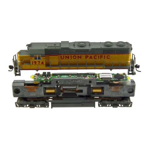
Your new MRC 0001642 decoder will virtually “drop-in” to a Kato SD70MAC & AC4400
diesel locomotive. Although easy, please follow instructions carefully.
Remove the locomotive body following Kato’s instructions. Remove the original circuit
board by very carefully sliding the circuit board slightly to the rear of the chassis. Lift
out. The 0001642 decoder is installed in the same location.
First, deburr the chassis (with emery cloth) any casting flash that may cause a sharp
edge under the location of the insulation tape. Then, using electrical or equiv plastic
tape, carefully tape the chassis in the areas shown in piture 2 to isolate the decoder
from the chassis. This must be done to prevent damage to the decoder. Align the
decoder and carefully insert it in the slots in the chassis. Gently press down on the rear
of the decoder while sliding it into position, being careful not to bend the vertical copper
motor contacts on the side of the chassis. Ensure the vertical copper contacts (on the
decoder) cover the thin vertical motor contacts. The motor contact must not touch the
loco chassis. The decoder installation is complete.
When replacing the body, ensure the copper contacts on the trucks are under the
horizontal chassis contacts.
PROGRAMMING
This decoder supports all programming methods including: register, paged CV, direct CV, and
programming on the main (ops mode programming).
MAKING A TEST TRACK
When you complete the decoder installation, we strongly recommend building a
test track with a 27 ohm resistor to limit current. Only test your installed decoder
on the test track. The test track may prevent damage from an incorrectly installed
decoder.
Note: The program track is NOT a test track. The program track does not use a current limiting
resistor. So it can’t protect an incorrectly installed decoder.
DCC base unit
Power supply
Test track
27 ohm resistor
picture 5. Diagram of test track
CAUTION:
The decoder must be isolated as shown. Apply electrical tape or plastic equiv.) tape
in the areas shown to prevent the electrical contacts from touching the chassis and
damaging the decoder.
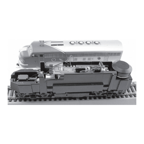
picture 2: the loco chassis that 0001642 decoder designed for
Chassis Slots
Tape here
Tape must extend down the sides as shown
Chassis Slots
Tape here
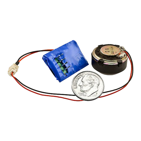
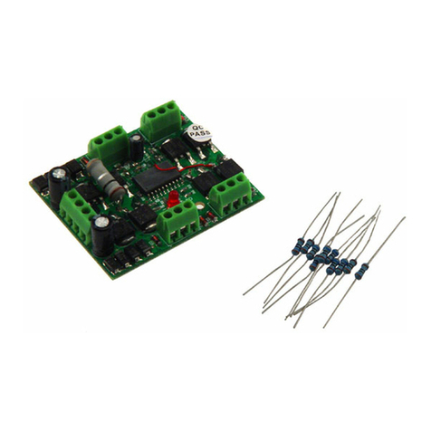
Picture3: #0001641 decoder
Picture1: #0001642 decoder
picture 4: the loco chassis that 0001641 decoder designed for
wrap tape
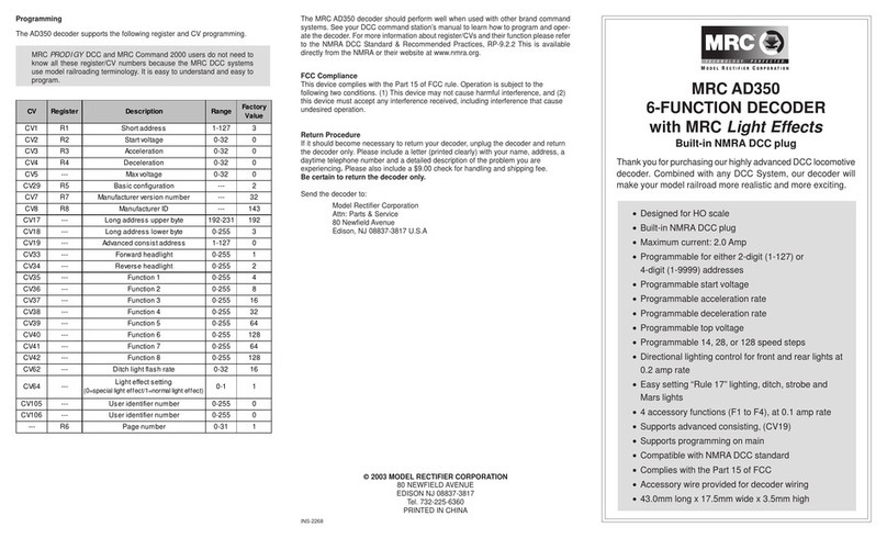
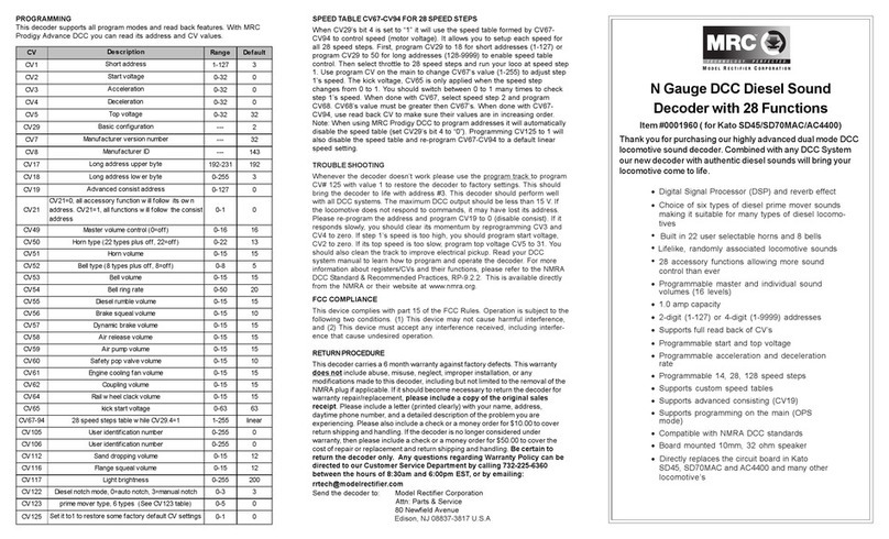
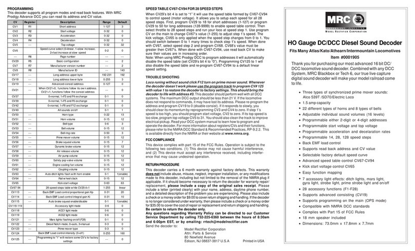
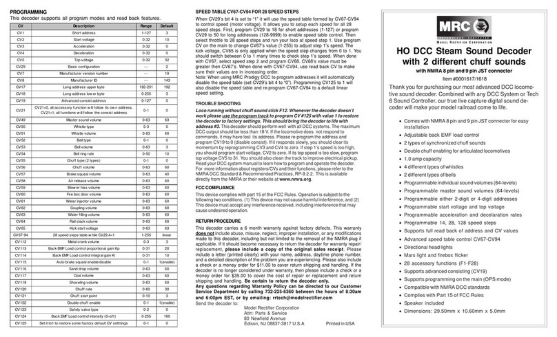
CV Register Description Range Default
CV1 R1 Short address 1-127 3
CV2 R2 Start voltage 0-32 0
CV3 R3 Acceleration 0-32 0
CV4 R4 Deceleration 0-32 0
CV5 --- Top voltage 0-32 32
--- R6 Page number --- ---
CV29 R5 Basic configuration --- 2
CV7 R7 Manufacturer version number --- 32
CV8 R8 Manufacturer ID --- 143
CV17 --- Long address upper byte 192-231 192
CV18 --- Long address lower byte 0-255 3
CV19 --- Advanced consist address 0-127 0
CV105 --- User identification number 0-255 0
CV106 --- User identification number 0-255 0
The 0001641 decoder is designed to fit most Atlas locomotives. The body shell and fuel tank
casting must be removed and the frame halves must be split to remove the original circuit
board. Wrap the whole notch on both frame halves with tape to prevent motor’s contact
(picture 4) from touching the chassis. Otherwise, the decoder will be destroyed if the motor’s
contact touches any unwrapped part of the chassis.

This manual suits for next models

1

Other MRC Media Converter manuals

MRC 0001750 User manual

MRC

MRC 0001750 User manual

MRC 0001711 User manual

MRC

MRC 0001711 User manual

MRC RSW-914 User manual

MRC

MRC RSW-914 User manual

MRC 0001958 User manual

MRC

MRC 0001958 User manual

MRC 0001952 User manual

MRC

MRC 0001952 User manual

MRC 0001628 User manual

MRC

MRC 0001628 User manual

MRC 0001956 User manual

MRC

MRC 0001956 User manual

MRC 1651 User manual

MRC

MRC 1651 User manual

MRC 0001955 User manual

MRC

MRC 0001955 User manual

MRC 0001907 User manual

MRC

MRC 0001907 User manual

MRC 0001659 User manual

MRC

MRC 0001659 User manual

MRC 0001827 User manual

MRC

MRC 0001827 User manual

MRC 0001811 User manual

MRC

MRC 0001811 User manual

MRC 0001663 User manual

MRC

MRC 0001663 User manual

MRC 0001629 User manual

MRC

MRC 0001629 User manual

MRC 0001803 User manual

MRC

MRC 0001803 User manual

MRC 0001910 2 User manual

MRC

MRC 0001910 2 User manual

MRC 0001805 User manual

MRC

MRC 0001805 User manual

MRC AD332 User manual

MRC

MRC AD332 User manual

MRC 0001802 User manual

MRC

MRC 0001802 User manual

MRC 0001611 User manual

MRC

MRC 0001611 User manual

MRC 0001644-2 User manual

MRC

MRC 0001644-2 User manual

MRC AD322 User manual

MRC

MRC AD322 User manual

MRC AD370 User manual

MRC

MRC AD370 User manual

Popular Media Converter manuals by other brands

Vertiv C48/24-1500 user manual

Vertiv

Vertiv C48/24-1500 user manual

M-system 18CE instruction manual

M-system

M-system 18CE instruction manual

TRENDnet TFC-110 Specifications

TRENDnet

TRENDnet TFC-110 Specifications

CTC Union FMC-1000M user manual

CTC Union

CTC Union FMC-1000M user manual

Raisecom RC905-EE1 user manual

Raisecom

Raisecom RC905-EE1 user manual

AMG AMG150-1G-S60-PD Installation Manual - Hardware

AMG

AMG AMG150-1G-S60-PD Installation Manual - Hardware

BARIX EXSTREAMER 205 quick start guide

BARIX

BARIX EXSTREAMER 205 quick start guide

Delta Electronics Delphi S24SA datasheet

Delta Electronics

Delta Electronics Delphi S24SA datasheet

NAD M51 owner's manual

NAD

NAD M51 owner's manual

Tascam iXR owner's manual

Tascam

Tascam iXR owner's manual

True blue power TC120 Installation manual and operating instructions

True blue power

True blue power TC120 Installation manual and operating instructions

IMC Networks iMcV-LIM Operation manual

IMC Networks

IMC Networks iMcV-LIM Operation manual

Pro ceed Digital Surround Decoder user manual

Pro ceed

Pro ceed Digital Surround Decoder user manual

thomann swissonic 497002 quick start guide

thomann

thomann swissonic 497002 quick start guide

Solar Converters EQ 12/24-50 manual

Solar Converters

Solar Converters EQ 12/24-50 manual

DCS Vivaldi Upsampler user manual

DCS

DCS Vivaldi Upsampler user manual

Sony XDBK-103 operating instructions

Sony

Sony XDBK-103 operating instructions

Storz OR1.avm Instructions for use

Storz

Storz OR1.avm Instructions for use

manuals.online logo
manuals.online logoBrands
  • About & Mission
  • Contact us
  • Privacy Policy
  • Terms and Conditions

Copyright 2025 Manuals.Online. All Rights Reserved.