manuals.online logo
Brands
  1. Home
  2. •
  3. Brands
  4. •
  5. MRC
  6. •
  7. Media Converter
  8. •
  9. MRC 0001958 User manual

MRC 0001958 User manual

CV Range Default
CV 1 1-127 3
CV 2 0-32 0
CV 3 0-32 0
CV 4 0-32 0
CV 5 0-32 32
CV 29 --- 2
CV 7 --- 32
CV 8 --- 143
CV17 192-231 192
CV 18 0-255 3
CV 19 0-127 0
CV 21 0-1 0
CV 49 1-16 16
CV 50 0-22 13
CV 51 0-15 12
CV 52 0-6 3
CV 53 0-15 12
CV 54 0-50 3
CV 55 0-15 12
CV 56 0-15 7
CV 57 0-15 12
CV 58 0-15 12
CV 59 0-15 12
CV 60 0-15 12
CV 61 0-15 12
CV 62 0-15 12
CV 64 0-15 12
CV 65 0-63 63
CV67-94 1-255 linear
CV105 0-255 0
CV106 0-255 0
CV112 0-15 12
CV113 0-31 20
CV114 0-31 10
CV115 0-1 1(enable)
CV116 0-15 12
CV117 0-255 200
CV122 0-3 3
CV123 0-5 0
CV124 0-255 160
CV125 0-1 0
Back EMF Load control intensity (0=off )
Set it to1 to restore some f actory default CV settnings
Long address upper byte
Long address low er byte
Advanced consist address
Diesel notch mode, 0=auto-notch, 3=manual notch
Prime mover type, 6 types
Flange squeal volume
Light brightness
User identification number
Sand dropping volume
Auto brake squeal enable/disable
Back EMF Load control proportional gain Kp
Back EMF Load control integral gain Ki
Rail w heel clack volume
Kick start voltage
28 speed steps table w hile CV29.4=1
User identification number
Brake squeal volume
Master volume control
Horn type
Hor n v olu me
Bell type
Safety pop valve volume
Engine cooling fan volume
Coupling volume
CV 21=0, all ac ces sory f unc tion w ill f ollow its ow n address.
CV 21=1, all f unc tions w ill f ollow the c ons ist address
Dynamic brake volume
Air release volume
Air pump volume
Bell volume
Bell ring rate
Diesel rumble volume
Description
Short address
Start voltage
Acceleration
Manufacturer version number
Manufacturer ID
Dec e le ratio n
Top voltage
Basic configuration
Printed in USA
N Gauge DC/DCC
Diesel Sound Decoder
Item #0001958 drop-in for Kato PA1
Thank you for purchasing our highly advanced DCC/DC 16 bit
locomotive sound decoder. Combined with any DCC System or
the MRC Tech 6, our new decoder with authentic diesel sounds
will bring your locomotives to life.
•Six types of synchronized diesel prime mover
with random associated locomotive sounds
•Adjustable back EMF load control with ultra slow
speed control
•1.0 amp capacity
•Programmable for either 2-digit (1-127) or 4-digit
(1-9999) addresses
•Programmable start voltage and top voltage
•Programmable acceleration and deceleration rate
•Programmable 14, 28/ 128 speed steps
•Directional lighting, (FO).
•Programmable user selectable different horns
and bells
•28 accessory functions (F1-F28)
•Supports full read back of CV's
•Supports advanced consisting (CV19)
•Supports programming on the main (OPS mode)
•Compatible with NMRA DCC standards
•Complies with part 15 of FCC regulations
•Programmable individual sound volumes
•13mm speaker included
SPEED TABLE CV67-CV94 FOR 28 SPEED STEPS
When CV29’s bit 4 is set to “1” it will use the speed table formed by CV67-CV94
to control speed (motor voltage). It allows you to setup each speed for all 28
speed steps. First, program CV29 to 18 for short addresses (1-127) or program
CV29 to 50 for long addresses (128-9999) to enable speed table control. Then
select throttle to 28 speed steps and run your loco at speed step 1. Use program
CV on the main to change CV67’s value (1-255) to adjust step 1’s speed. The
kick voltage, CV65 is only applied when the speed step changes from 0 to 1. You
should switch between 0 to 1 many times to check step 1’s speed. When done
with CV67, select speed step 2 and program CV68. CV68’s value must be
greater then CV67’s. When done with CV67-CV94, use read back CV to make
sure their values are in increasing order.
Note: When using MRC Prodigy DCC to program addresses it will automatically
disable the speed table (set CV29’s bit 4 to “0”). Programming CV125 to 1 will
also disable the speed table and re-program CV67-CV94 to a default linear
speed setting.
TROUBLE SHOOTING
This decoder should perform well with all DCC systems. The maximum DCC
output should be less than 15 V. If the locomotive does not respond to com-
mands, it may have lost its address. Please re-program the address and program
CV19 to 0 (disable consist). If it responds slowly, you should clear its momentum
by reprogramming CV3 and CV4 to zero. If step 1’s speed is too high, you should
program start voltage, CV2 to zero. If its top speed is too slow, program top
voltage CV5 to 31. You should also clean the track to improve electrical pickup.
Read your DCC system manual to learn how to program and operate the decoder.
For more information about registers/CVs and their functions, please refer to the
NMRA DCC Standard & Recommended Practices, RP-9.2.2. This is available
directly from the NMRA or their website at www.nmra.org. Whenever the
decoder doesn’t work please use the program track to program CV# 125 with
value 1 to restore the decoder to factory settings. This should bring the decoder
to life with address #3.
FCC COMPLIANCE
This device complies with Part 15 of the FCC Rules. Operation is subject to the
following two conditions. (1) This device may not cause harmful interference,
and (2) This device must accept any interference received, including interfer-
ence that may cause undesired operation.
RETURN PROCEDURE
This decoder carries a 6 month warranty against factory defects. This warranty does
not include abuse, misuse, neglect, improper installation, or any modifications made
to this decoder, including but not limited to the removal of the NMRA plug if applicable.
If it should become necessary to return the decoder for warranty repair/replacement,
please include a copy of the original sales receipt. Please include a letter (printed
clearly) with your name, address, daytime phone number, and a detailed description of
the problem you are experiencing. Please also include a check or a money order for
$10.00 to cover return shipping and handling. If the decoder is no longer considered
under warranty, then please include a check or a money order for $50.00 to cover the
cost of repair or replacement and return shipping and handling. Be certain to return
the decoder only.
Any questions regarding Warranty Policy can be directed to our Customer
Service Department by calling 732-225-6360 between the hours of 8:30am
and 6:00pm EST, or by emailing: rrtech@modelrectifier.com
Send the decoder to: Model Rectifier Corporation
Attn: Parts & Service
80 Newfield Avenue
Edison, NJ 08837-3817 U.S.A
PROGRAMMING
This decoder supports all programming modes and supports read back of all CV’s
with most dcc systems.
Function Idle/Moving
F0 Headlight On/Off [only forward]
F1 Bell on/off
F2 Horn
F3 air release
F4 Coupling 1
F5 Brake release (idle) / brake squeal (moving)
F6 Dynamic brake on/off
F7 Air hose firing/uncoupling lever
F8 3 times will shut down when in idle / Manual notch down
F9 Engine cooling fan / Manual notch up
F10 Rail wheel clack (only moving)
F11 Traction air compressor
F12 Change prime diesel mover type (CV123, 6 types)
F13 Master volume reduce by 1 / air release when reach minimal
F14 Master volume increase by 1/ air release when reach maximal
F15 Air compressor
F16 Flange squeal
F17 Air release
F18 Change bell type (8 types plus off)
F19 Horn type s elect (total 22 different horns plus off)
F20 Associated loco sound
F21 Change bell volume and turn on the bell
F22 Change horn volume
F23 Change diesel rumble volume
F24 Safety valve pop
F25 Air release
F26 Flange noise
F27 Sand drop
F28 Air release
CV123 Prime mover
SD39, SD40, SD40A, SD40-2, SD40T-2, SD45. SDP45, SD45X, SD45-2,
SD45T-2, F45, FP45, DDA40X, GP15T, GP39, GP39-2, GP40, GP40-2
SW1000, SW1001, SW1500, SW1504, MP15DC, MP15AC, MP15T,
GP38, GP38-2, SD38, SD38-2, GP15AC, GP15-1
2 EMD710 SD70AC, SD70M-2
3 ALCO 244
4 ALCO 539T
F2A/B, F3A/B, F7A/B, F9A/B, BL1, BL2, FP7, FL9, FT, GP7, GP9, GP18,
GP28, E6, E7, E8, E9, NW2, NW3, NW4, SW1, SW7, SW8, SW9, SW600,
SW900, SW1200
5 EMD567
0 EMD645E
1 EMD645
Suitable for the locomotive
RS-3, PA1, PB1
S-2, S-4, RS-1, RSC-1, RSD-1, DL-105, DL107, DL-108, DL-109, DL-110
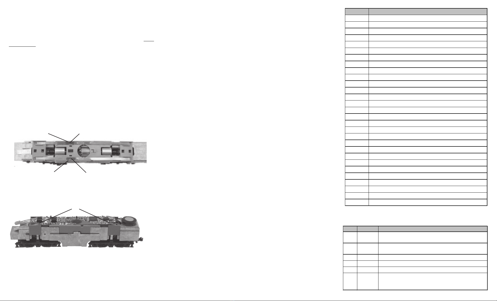
bend the 4 spring contacts on the PCB
Figure 2.
Figure 1.
trim off some plastic apply tape
apply tape
trim off some plastic
INSTALLATION
Your new Sound Decoder will virtually “drop-in” to a your Kato N scale PA1
series diesel locomotive. It may fit in many other N scale locomotives with slight
modification. Refer to the instructions that came with your Kato PA1
locomotive for removal of the body shell. Remove the original circuit board
by very carefully removing the plastic clip and sliding the PCB out. Don’t
lose the clip. There are two wheel pickup contact strips. These strips
must be wrapped with tape approx. 1/4 wide (as shown in the image
below) to prevent them from touching the motor leads. Trim off some
material from the plastic cradle under the motor brush tab area to
compensate for the tape thickness. After applying the tape and trimming
the plastic, reinstall the strips. before installing the new decoder, bend the
spring contacts under the rear of the decoder approx 45 degrees to
provide correct contact. Now, install the decoder in place of the original
PCB and reinstall the plastic clip you removed earlier. Apply a strip of tape
over the clip & down the chassis sides to help hold the decoder in place.
Re-install the body shell. Now your loco is ready to go to work on your
railroad.
DCC OPERATION
The decoders have been factory programmed with address #3, 28/128
speed steps and maximum top voltage. Select the “Run” mode of your
DCC system and select or acquire address #3. Move up the throttle and
the loco should move.
The decoder has 6 types of diesel prime mover sounds. You can use
F12 to change the prime mover sounds. You can also program CV123
to value of 0 to 5 to select the following primer mover for matching your
diesel engine. The CV123 table shows the 6 prime mover sounds and
their associated locomotive types.
The decoder has a start up and shut down feature. If the loco has been
previously shut down, you have to start up the engine by simply press-
ing any numbered function button. To shut down the engine you must
bring the loco to idle and then press F8 three times.
This decoder has 22 different horns. You can use F19 or program CV50
to select these 22 horns. You can also use F18 or program CV52 to
select different 8 bell sounds.
Most of the sounds have their own volume control CV. There is also a
master sound volume control CV49. Also F13 will reduce the master
volume by 1 (you will hear an air release when you reach CV49=1).
Pressing F14 will increase volume by 1 (you will hear an air release
when you reach CV49=16). Programming CV49 to 0 will shut the sound
off.
The decoder is defualt to automatic notching. You can program CV122
to 3 to set manual notching for realistic operation. And then use F9 to
notch up and use F8 to notch down. This simulates the way a real
locomotive operates.
This decoder is equipped with adjustable back EMF closed loop speed
control. Its proportional gain (CV113), integral gain (CV114) and derivative
gain (fixed) are pre-tuned for most locomotives. We recommend that you
do not change these settings. Too much gain may cause the motor to
oscilate (become unstable). Too little gain may cause slow response.
Please get some basic knowledge of PID feedback control before trying to
adjust CV113/114.
There are many more program features available with this decoder.
Please refer to the CV Chart to explore other features of the decoder.
Note: Bell, Dynamic Brake and Rail Wheel Clack cannot play at the same
time. If you activate the Bell sound [F1], while either the Dynamic Brake or
Rail Wheel Clack sounds are activated, the Bell sound will override the
other 2 sounds. Rail Wheel Clack cannot play while the loco is in idle.
When you turn off Dynamic Brake and Rail Wheel Clack sound there will
be one second delay.
DC OPERATION
With DC operation only the last programmed prime mover sound will
play, and you can’t control bells, horns, etc. We recommend you to use
MRC Tech 6 power pack, [item no. 0001200], for your DC operation. It
will enable the full range of sounds on a DC system.

Other MRC Media Converter manuals

MRC 0001802 User manual

MRC

MRC 0001802 User manual

MRC AD322 User manual

MRC

MRC AD322 User manual

MRC 0001644-2 User manual

MRC

MRC 0001644-2 User manual

MRC 0001922 User manual

MRC

MRC 0001922 User manual

MRC 0001663 User manual

MRC

MRC 0001663 User manual

MRC 0001657 User manual

MRC

MRC 0001657 User manual

MRC Sheer Brilliance 0001638 User manual

MRC

MRC Sheer Brilliance 0001638 User manual

MRC 0001656 User manual

MRC

MRC 0001656 User manual

MRC 0001628 User manual

MRC

MRC 0001628 User manual

MRC 0001645 User manual

MRC

MRC 0001645 User manual

MRC 0001916 User manual

MRC

MRC 0001916 User manual

MRC 0001641 User manual

MRC

MRC 0001641 User manual

MRC 0001907 User manual

MRC

MRC 0001907 User manual

MRC 1650 User manual

MRC

MRC 1650 User manual

MRC 0001922 User manual

MRC

MRC 0001922 User manual

MRC 0001639 User manual

MRC

MRC 0001639 User manual

MRC 0001821 User manual

MRC

MRC 0001821 User manual

MRC 0001629 User manual

MRC

MRC 0001629 User manual

MRC 0001902 User manual

MRC

MRC 0001902 User manual

MRC 1651 User manual

MRC

MRC 1651 User manual

MRC 0001819 User manual

MRC

MRC 0001819 User manual

MRC 0001910 2 User manual

MRC

MRC 0001910 2 User manual

MRC 0001817 User manual

MRC

MRC 0001817 User manual

MRC 0001750 User manual

MRC

MRC 0001750 User manual

Popular Media Converter manuals by other brands

Precision Power PowerClass DAC348 owner's manual

Precision Power

Precision Power PowerClass DAC348 owner's manual

MSB Technology The Reference DAC user guide

MSB Technology

MSB Technology The Reference DAC user guide

Extron electronics DSC 3G-HD A Setup guide

Extron electronics

Extron electronics DSC 3G-HD A Setup guide

Antrica SpotBox4K user manual

Antrica

Antrica SpotBox4K user manual

Transition Networks CPSVT26XX Specifications

Transition Networks

Transition Networks CPSVT26XX Specifications

Amperes DA2208 instruction manual

Amperes

Amperes DA2208 instruction manual

StarTech.com UVCHDCAP quick start guide

StarTech.com

StarTech.com UVCHDCAP quick start guide

CYP AU-11SA-4K22 Operation manual

CYP

CYP AU-11SA-4K22 Operation manual

Stahl 9786 Series Handbook

Stahl

Stahl 9786 Series Handbook

Interlogix ACL800FL-CONV-W-RS485 installation manual

Interlogix

Interlogix ACL800FL-CONV-W-RS485 installation manual

NetcamViewer Monitor quick start guide

NetcamViewer

NetcamViewer Monitor quick start guide

Comnet CWFE2SCM2 quick start guide

Comnet

Comnet CWFE2SCM2 quick start guide

ZeeVee ZvPro 800 Configuration guide

ZeeVee

ZeeVee ZvPro 800 Configuration guide

Transition Networks TR-CF-01 user guide

Transition Networks

Transition Networks TR-CF-01 user guide

RGBlink VSP 168S user manual

RGBlink

RGBlink VSP 168S user manual

Atlona AT-HDR-M2C installation guide

Atlona

Atlona AT-HDR-M2C installation guide

Castwin DME-9724HM Operation manual

Castwin

Castwin DME-9724HM Operation manual

Panduit ATLONA AT-HDVS-RX Faq

Panduit

Panduit ATLONA AT-HDVS-RX Faq

manuals.online logo
manuals.online logoBrands
  • About & Mission
  • Contact us
  • Privacy Policy
  • Terms and Conditions

Copyright 2025 Manuals.Online. All Rights Reserved.