MRC 0001656 User manual

HO Gauge Synchronized
Steam Sound Decoder with
28 Accessory Functions
Item #0001656
Thank you for purchasing our highly advanced DCC loco-
motive sound decoder. Combined with any DCC System,
our new decoder with authentic steam sound truly will
make your model railroad come to life.
•Synchronized steam chuff with random sounds
•8 selectable chuff sounds (4 regular/ 4 articulated)
•User selectable 14 different whistles and 4 bells
•28 accessory functions allowing more sound
control than ever
•Programmable individual sound volumes
• 1.5 amp capacity
•Programmable for either 2-digit (1-127) or 4-digit
(1-9999) addresses
•Programmable start voltage
•Programmable acceleration rate
•Programmable deceleration rate
•Programmable top voltage
•Programmable 14, 28, 128 speed steps
•Selectable factory default speed curve
•Directional lighting control for front and rear lights at
0.2 amp rate.
•Realistic firebox flicker and accessory lighting
•Programmable chuff rate and chuff starting point
•Supports advanced consisting (CV19)
•Supports programming on the main, (Ops mode)
•Compatible with NMRA DCC standard
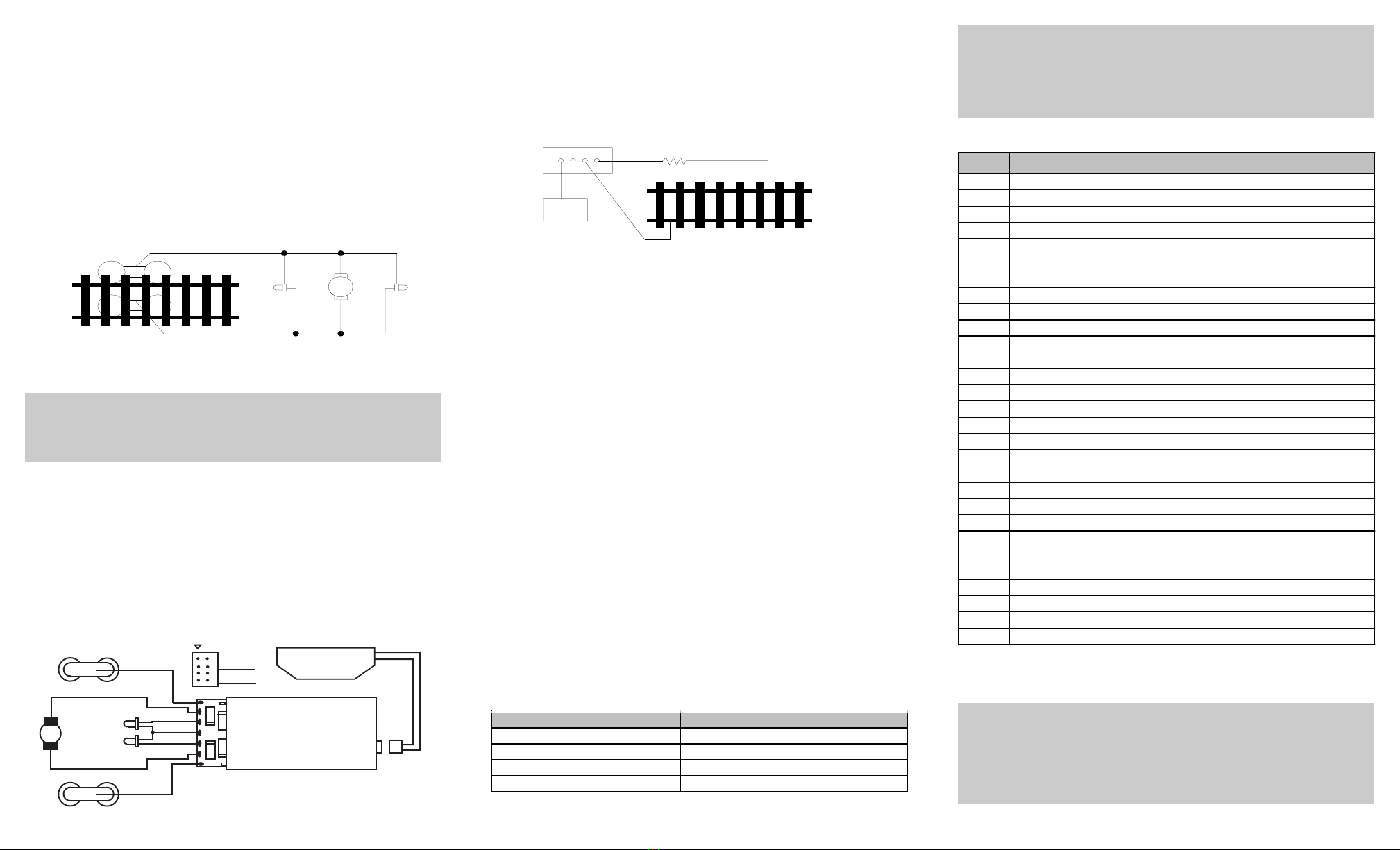
•NMRA 8 pin plug included for easy installation
•Complies with the part 15 of FCC
•28mm speaker included
•Dimensions: 45.0mm x 18.0mm x 6.2mm
TROUBLE SHOOTING
This sound decoder should perform well with all DCC systems. See your DCC
system manual to learn how to program and operate the decoder. For more
information about register/CVs and their functions, please refer to the NMRA
DCC Standard & Recommended practices, RP-9.2.2 this is available directly from
the NMRA or their website at www.nmra.org.
Due to the nature of all sound decoders, the CV read back may not work.
Whenever the decoder doesn’t work it may lose its address. Please use program
track to re-program the loco address or program CV# 125 with value 1 to
restore the decoder to factory setting. This should bring the decoder to life.
FCC COMPLIANCE
This device complies with the part 15 of FCC rule. Operation is subject to the
following two conditions. (1) This device may not cause harmful interference,
and (2) This device must accept any interference received, including interfer-
ence that cause undesired operation.
RETURN PROCEDURE
If it should become necessary to return your decoder, unplug the decoder and
return the decoder only. Please include a letter (printed clearly) with your name,
address, a daytime telephone number, and a detailed description of the problem
you are experiencing. Please also include a $19.00 check for shipping and
handling. Be certain to return only the decoder.
Warranty does not include abuse, neglect, or using this product for
anything other than it’s intended purpose. Warranty coverage will be
handled on a case by case basis, and other charges may apply for
Send the decoder to:
Model Rectifier Corporation
Attn: Parts & Service
80 Newfield Avenue
Edison, NJ 08837-3817 U.S.A
PROGRAMMING FOR DCC OPERATION – DIGITAL MODE
This decoder supports all program methods including register, paged mode,
direct CV programming, and programming on the main (OPS mode)
2007 MODEL RECTIFIER CORPORATION
80 NEWFIELD AVENUE
EDISON, NJ 08837-3817 Printed in USA
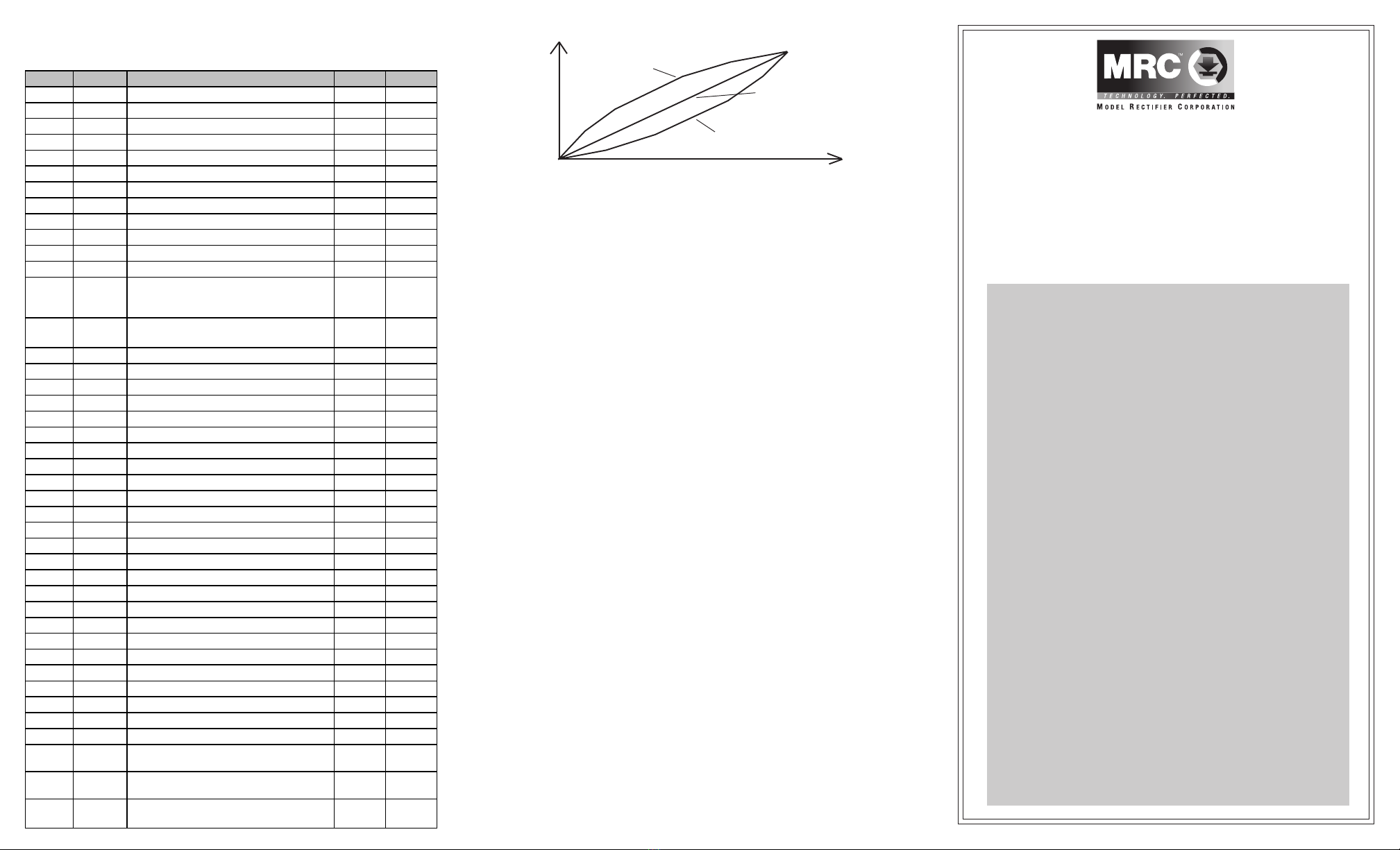
Speed curve of different value of CV #124
Output
CV #124 =1
CV #124 =2
CV #124 = 0, Linear
CV Register Description Range Default
CV1 R1 Short address 1-127 3
CV2 R2 Start voltage 0-32 0
CV3 R3 Acceleration 0-32 8
CV4 R4 Deceleration 0-32 8
CV5 --- Top voltage 0-32 32
--- R6 Page number --- ---
CV29 R5 Basic configuration --- 2
CV7 R7 Manufacturer version number --- 32
CV8 R8 Manufacturer ID --- 143
CV17 --- Long address upper byte 192-231 192
CV18 --- Long address lower byte 0-255 3
CV19 --- Advanced consist address 0-127 0
CV49 Master volum e control(0=off, 1=low,
2=mid,3=max) 0-3 2
CV50 --- Whistle type 0-13 0
CV51 --- Whistle volume 0-3 3
CV52 --- Bell type 0-3 0
CV53 --- Bell volume 0-3 3
CV54 --- Bell ring rate 0-50 10
CV55 --- Chuff type 0-3 0
CV56 --- Chuff volume 0-3 3
CV57 --- Brake squeal volume 0-3 1
CV58 --- Air release volume 0-3 3
CV59 --- Blower hiss volume 0-3 3
CV60 --- Fire box door volume 0-3 3
CV61 --- Injector volume 0-3 3
CV62 --- Coupling volume 0-3 3
CV63 --- Air pump volume 0-3 0
CV105 --- User identification number 0-255 0
CV106 --- User identification number 0-255 0
CV112 --- Conductor volume 0-3 3
CV115 --- Auto brake squeal enable/disable 0-1 1(enable)
CV116 --- Shoveling volume 0-3 3
CV117 Air pump type 0-2 0
CV118 Accessary light effect 0-3 0
CV119 --- Air hose fire volume 0-3 3
CV120 --- Chuff rate 0-30 12
CV121 --- Chuff start point 0-7 3
CV122 --- Double chuff enable 0-1 1(enable)
CV123 --- Back emf on/off(1=on, you must have a motor
to get chuff sound) 0-1 0
CV124 --- Speed curve select(0=linear, 1=slow increase
at slow speed, 2=fast increase at slow speed) 0-2 0
CV125 --- Program it to1 w ill restore CV's 1,2,3,4,5 to
factory default settng --- 0
CV21 --- 0
When CV21=0, all accessory function w ill
follow its ow n address. When CV21=1, all
functions w ill follow the consist address
0-1

INSTALLATION
If your loco has a NMRA 8 pin receptacle, simply remove the dummy plug and
match first pin and plug in the decoder. Otherwise it is quite a challenge to install
a decoder into a loco. You should have some basic electrical knowledge and
soldering skills. If you do not have the above requirements, please ask the dealer
for help in installation.
Figure 1 shows the electrical circuit of most standard locos. The terminals of the
motor and light(s) are directly connected to the wheel pickup. Each type of loco
has its own method of electrical pickup and distribution. The connection between
the wheels, motor and light(s) could be wires, clips, the body or chassis, PC
board or any other type of conductor. First, figure out your loco’s electrical
wiring and how to disconnect (isolate) the motor and light(s).
Note: The ‘X’ marks indicate
where to disconnect (isolate).
The decoder will be inserted between the wheel pickup and the motor.
Each manufacturer and loco may have different ways of decoder
installation. There is no standard rule for installing decoders. It is
always better to consult the loco manufacturer on how to install a
decoder in that particular loco.
Figure 2 shows how to wire the decoder. After disconnecting the motor
terminals from the pickup, connect the red wire to the right side pickup and the
black wire to the left side pickup. Connect the orange wire to the motor terminal
that was originally connected to the right pickup. Connect the gray wire to the
motor’s other terminal. Connect the front light to the blue wire and the white wire.
Connect the rear light to the blue wire and the yellow wire.
The blue wire is the common terminal for lights and accessory functions. You
may use the black wire or the red wire to replace the blue wire. This is useful
when isolating one of the light terminals from the pickup is difficult. Wiring the
bulb this way will make the light dimmer. If your loco has only a front light, you
should connect the white and the yellow wires together.
MAKING A TEST TRACK
Before you begin decoder installation, we strongly recommend building a test
track with a 27 ohm resistor to limit current. Only test your installed decoder on
the test track. The test track may prevent damage from an incorrectly installed
decoder.
Note: The program track is NOT a test track. The program track does not use a
current limiting resistor. So it will not protect an incorrectly installed decoder.
TESTING
The decoders has been factory programmed with address #3, 28/128 speed
steps and maximum top voltage. Never run the installed decoder on your
layout without first successfully running on test track. Otherwise, you
may damage the decoder if it is not wired correctly or if you have not properly
isolated the motor and lights.
To test, place the loco on the test track. Select the “Run” mode of your DCC
system and select or acquire address #3. Move up the throttle and the loco
should move forward. Push the light button [F0] and the front headlight should
come on. Change the direction of the loco and the loco should change direction
and the rear headlight (if equipped) should come on. The loco cannot reach full
speed, due to the resistor. If all above occurs, you passed the test. Congratula-
tions!
Do not run the loco for an extended period of time on the test track or the resistor
will overheat.
If your installed decoder does not pass the test, find the problem, correct it and
test it again. As long as you test the decoder on the test track there is little chance
of damaging the decoder. That is why the test track is so important. Also do not
corrent limiting resistor. Sound decoders need full power to the program track to
install all programming instructions.
LIGHT EFFECTS
There are 4 solder tabs on the bottom of the decoder for the accessory lighting
features marked “ACC1” and “ACC2”, with the two innermost tabs used as the
common. “ACC1” is for the adjustable light effects, [see CV 118 chart]. “ACC2” is
used for the firebox flicker effect. “ACC2” is non-adjustable, and is controlled on/
off with F3, which also controls the accessory lights.
LIGHT EFFECT PROGRAMMING CHART FOR CV#118
All the decoder’s light outputs are track output voltage (around
14V) supplied by your DCC system. They are designed for 12V
light bulbs. Please contact your loco manufacturer for lights’
operation voltage. If you have a 1.5V bulb use 1k ohm resistor or
LED, you should connect a 2k ohm resistor in series to one of the
leads to limit current.
STEAM SOUNDS / ACCESSORY FUNCTION CHART
*NOTE- Functions F25 through F28 are fine tuning adjustments while the loco is
running.
Due to limitations in some types of DCC systems or older DCC
systems, some of the sound/accessory functions may not be able
to be accessed. Also, you might be limited to factory default CV
settings. This decoder supports the new N.M.R.A. protocols that
use up to function 28, (F28). Right now only MRC prodigy2 has 28
functions.
Figure 1. Connection of standard locomotive
Right side pickup
Front
light Motor Rear
light
Left side pickup
X
X
X
X
X
X
Figure 2. 0001656 decoder wiring diagram
1
orange
black
red
orange
gray
yellow
white
right
blue
headlight
rear light
black
left
black
28mm speaker
with cap
DCC base unit
Power supply
Test track
27 ohm resistor
Figure 3. Diagram of test track
CV118 ACC#1 Light e ffe ct
0 Gyra light
1 Mars light
2 Strobe light
3Steady on/off,(used f or interior cab light)
Function Idle/Moving
F0 Directional Lights on/off
F1 Bell on/off
F2 Whis tle
F3 short Air release and accessary light on/off
F4 Coupling
F5 Brake squeal
F6 Conductor
F7 Fire box door open/close
F8 Sand drop
F9 Revers er
F10 Water
F11 Blower hiss
F12 Master volume: max, mid, min, off 4 levels
F13 Coal auger
F14 Air Hos e fire
F15 long air release
F16 Shoveling
F17 air pump
F18 bell type
F19 Whistle type select*
F20 Bell ring rate
F21 Bell volme
F22 Whistle volume control
F23 Chuff volume control
F24 Chuff type
F25 Chuff rateslow down (CV120 decrease 1)with associated loco sound
F26 Chuff rate speed up (CV120 increase 1) with associated loco sound
F27 Start moving chuff rate slow down (CV121decrease 1) with associated loco sound
F28 Start moving chuff rate speed up (CV121 increase 1) with associated loco sound
Other MRC Media Converter manuals