MSI 610BF User manual

Chapter 1
1-1 Preface.....................................................................................................1
1-2 Key Feature..............................................................................................1
Chapter 2
Hardware Installation....................................................................................3
2-1 Unpacking.................................................................................................3
2-2 The Diagram of 610BF 612BF.................................................................4
2-3 Quick Reference for Jumpers, Connectors & Expansion Socket.............5
2-4 Installation Steps......................................................................................6
2-5 Jumper Settings........................................................................................6
2-6 System Memory (DRAM)..........................................................................8
2-7 Central Processing Unit (CPU).................................................................8
2-8 Expansion Cards......................................................................................9
2-9 External Connectors.................................................................................10
Chapter 3
AWARD BIOS SETUP...................................................................................1
3-1 STANDARD CMOS SETUP.....................................................................17
3-2 BIOS FEATURES SETUP........................................................................20
3-3 Advanced Chipset Features Setup..........................................................22
3-4 Integrated Periperals................................................................................24
3-5 POWER MANAGE MENT SETUP ...........................................................27
3-6 PNP PCI CONFIGURATION SETUP........................................................29
3-7 PC Health Status.......................................................................................31
3-8 Frequency Voltage Control........................................................................31
3-9 Defaults Menu............................................................................................32
3-10 Supervisor User Password Setting...........................................................32
3-11 EXIT Selecting.........................................................................................33
3-12 POST Messages.....................................................................................33
3-13 POST Codes............................................................................................37
Chapter 4
10BF/ 12BF Driver Installation.............................................................43
4-1 Software Installation ....................................................................................43
4-2 Keyboard Password Hot-Key PS 2 Mouse Power On..................................44
i
TABLE OF CONTENT

Chapter 1
1-1 Preface
Thank you for chosen 610BF 612BF mainboard. It is a multifunction motherboard with most
flexibility you can find in today’s computer market. The motherboard integrate Celeron TM
(PPGA) processor interface into a compact PC AT compatible system along with PCI local bus
and the most recent interface AMR (Audio Modem Riser card). Moreover, this motherboard
using newest DDM (Dynamic Display Memory) architecture to increase systems display
performance and many other new feature that meets future specification.
1-2 Key Feature
The 610BF 612BF are design for the PC user who wants highest possible quality and value in
a small package . This motherboard include:
Support Jumpless solution,can setting Front Side Bus Frequency (CPU Host Clock)
,and CPU ratio in BIOS SETUP “Frequency / Volotage Control“.
Built-In High performance 3D AGP VGA:
Support 1MB share memory for VGA.
Include 4MB Display Cache (For 612BF only).
3D Hyper Pipelined Architecture.
3D Graphics Visual Enhancements.
3D Graphics Texturing Enhancements.
Up to 1600x1200 in 8-bit Color at 85Hz Refresh.
H W Motion Compensation Assistance for S W MPEG2 Decode.
Software DVD at 30fps.
Built-In High performance 3D Audio:
Fully Compliant AC97 Analog I O Component.
48-Terminal TQFP package.
Multibit △ Converter Arhitecture for improved S N ratio greater than 90dB.
16-Bit Stereo Full-Duplex Codec.
4 Analog Line-Level Stereo Input.
High Quality CD Input with Ground Sense.
Stereo Line Level Output.
Multi-Speed Support : Provide 66 75 83 95 100 112 117 124 133MHz Front Side Bus
Frequency to support Intel Celeron PPGA on a ZIF socket 370 interface.
Chipset: Intel 810L Chiset for 610BF; Intel 810 DC-100 Chipset for 612BF.
DRAM Memory Support: support two 168-pin DIMMS(3.3V)from a memory size between
8MB to 256MB using 16Mb 64Mb technology ( 512MB using 128Mb technology ).
AMR and PCI expansion Slots: Provide one AMR slot, four PCI slot.
Super Multi-I/O: Provides two high-Speed UART compatible serial ports and one parallel
port with EPP and ECP capabilities. Two floppy drives of either 5.25” or 3.5” (1.44MB or
2.88MB) are also supported without an external card.
1

PCI Bus Master IDE Controller and ULTR DMA 33, 33/66 (for 612B only) : On-board PCI
Bus Master IDE controller with two connectors that supports four IDE devices in two
channels, provides faster data transfer rates, and supports Enhanced IDE devices such as
Tape Backup, CD-ROM 、ZIP、LS-120 Drives. This controller also supports PIO Modes and
Bus Master IDE DMA 33 66 MB S.
ACPI supporting for OS Directed Power Management
Keyboard /PS/2 Mouse Power On: When use ATX power supply and JP6 1-2 closed,
choose power on function by password in BIOS , can control power supply on by keyboard
instead of power button .
Ring-in Wake up: When Ring-In the system can wake up from SMI Mode.
Ring-in Power On: When Ring-In the system can power on automatic by this function.
Wake on Lan: When Wake on Lan the system can power on automatic by this function.
RTC Power On: Enabled RTC Power On function, you can setting RTC alarm to power on
the system at the time length you setting .
Power Button: Press the button will place the system power on off.
Support Software Power OFF Function.
Power Support: Efficient PWM switching power instead of traditional Linear Voltage
Regulator to prevent power component from being burned-out.
Meets PC99 Requirements.
Optional IRDA and PS/2: This motherboard supports an dedicated 16C550 standard
UART,supporting infrared communication module for wireless interface and PS 2 mouse
cable set.
USB Port Connector: This motherboard supports two USB port connectors for USB devices.
PC Health Monitoring : To track PC CPU temperature, system voltage and fan speed.
When current temperature over warning temperature system will have alarm to warning.
AC recovery ON/O control by BIOS
Baby AT Form Factor: Dimensions 22cm x 22cm.
Chapter 2
Hardware Installation
2

2-1 Unpacking
This mainboard package should contain the following:
The 610BF 612BF mainboard
USER’S MANUAL for mainboard
Cable set for IDE x1, Floppy x1 ,COM x1
CD for Drivers PACK
The mainboard contains sensitive electronic components which can be easily damaged by
electron-static, so the mainboard should be left in its original packing until it is installed.
Unpacking and installation should be done on a grounded anti-static mat.
The operator should be wearing an anti static wristband, grounded at the same point as the
anti-static mat.
Inspect the mainboard carton for obvious damage. Shipping and handling may cause damage
to your board. Be sure there are no shipping and handling damages on the board before
proceeding.
After opening the mainboard carton, extract the system board and place it only on a grounded
anti-static surface component side up. Again inspect the board for damage.
Press down on all of the socket IC’s to make sure that they are properly inserted. Do this only
on with the board placed on a firm flat surface.
Warning: Do not apply power to the board if it has been damaged.
You are now ready to install your mainboard. The mounting hole pattern on the mainboard
matches the IBM-AT system board.
It is assumed that the chassis is designed for a standard IBM XT AT main board mounting.
Place the chassis on the anti-static mat and remove the cover.
Take the plastic clips, Nylon stand-off and screws for mounting the system board, and keep
them separate.
2-2 10BF/ 12BF Motherboard Diagram
3

Figure 2-1
2.3 Quick Reference for Jumpers, Connectors &
Expansion Socket
4

Jumpers
Jumper Name Description Page
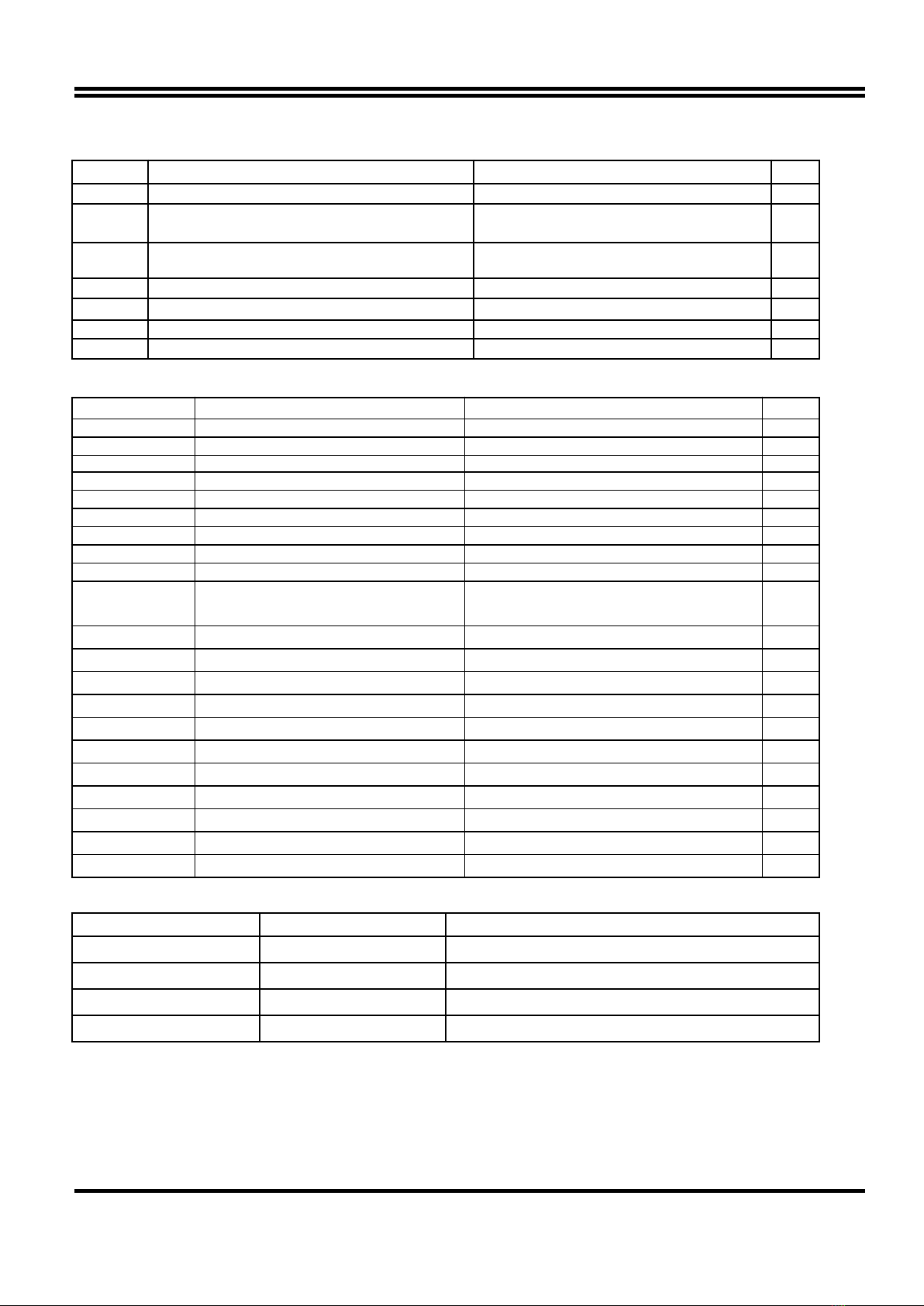
JP1 CPU Bus Frequency Selection 1-2 :100MHZ , 2-3:66MHz p. 6
JP3 V I O Voltage 1- 2 :For V I O 3.45V (Default)
3-4 :For V I O 3.52V p.7
JP6 Keyboard Power on Function (K.B.Voltage) 1-2 : 5VSB for ATX Power Supply
2-3 : VCC p. 8
JP7 Case cover open detection 2-Pin Block p. 7
JP9 Clear Keyboard Power On Password setting 1-2 Default ; 2-3 Clear Password p. 7
JP12 Codec Master Slave Mode Control 1-2 Master ; 2-3 slave p. 7
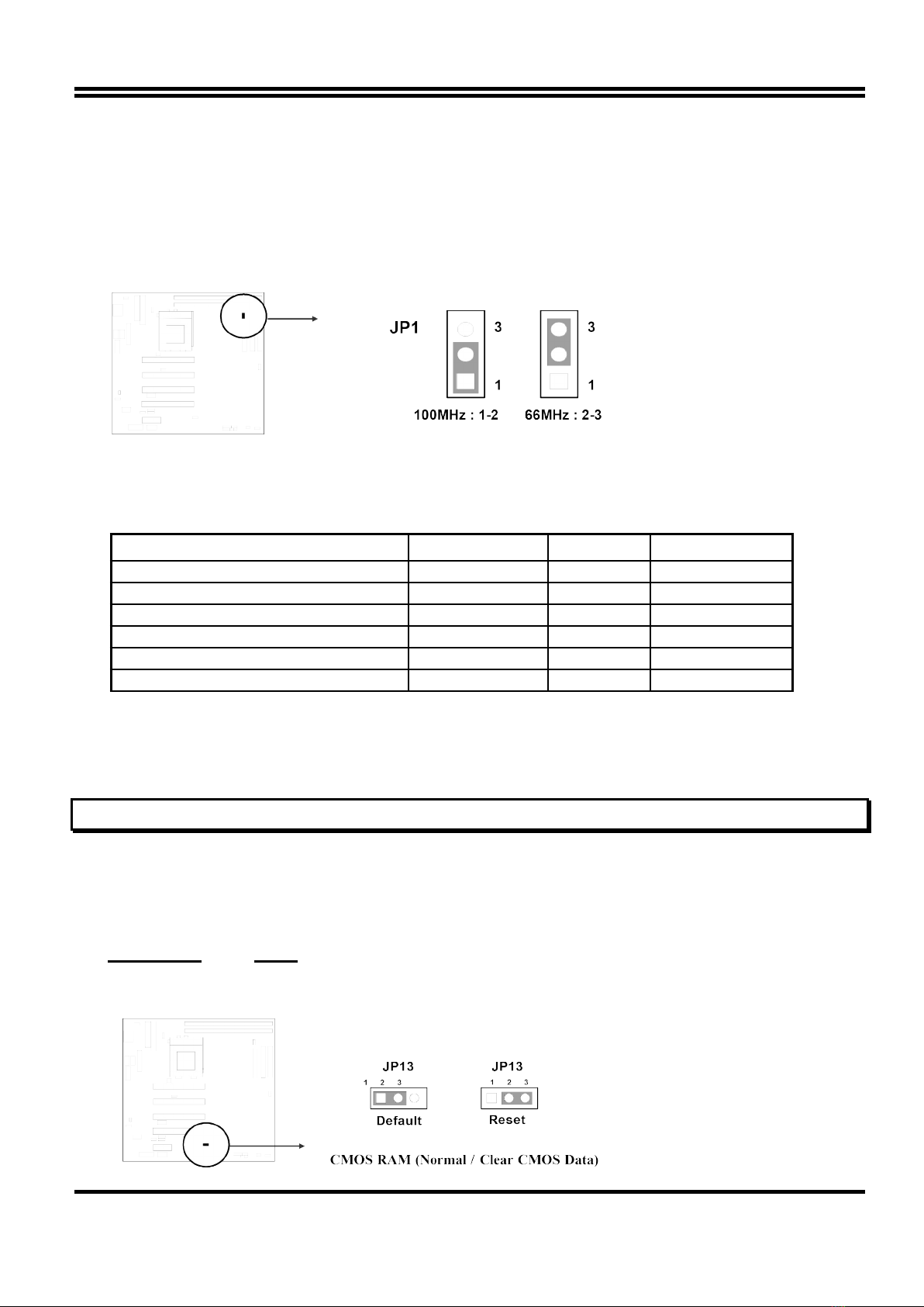
JP13 CMOS RAM Clear 1-2 Default for R.T.C. ; 2-3 Reset R.T.C. p. 6
Connectors
Connector Name Description Page
JKB1 Keyboard Connector 5-Pin Female p.10
USB PORT USB Port Connector 10-Pin Block p.13
JMS1 PS 2 MouseConnector 6-Pin Block p.11
COM1,COM2 Serial Port COMA&COMB 10-Pin Block p.11
LPT1 Parallel Port Connector 26-Pin Block p.11
FDD1 Floppy Driver Connector 34-Pin Block p.11
IDE1 Primary IDE Connector 40-Pin Block p.12
IDE2 Secondary IDE Connector 40-Pin Block p.12
VGA1 VGA Connector 16-pin Block p.14
FAN1
FAN2,FAN3
FAN Connector 1-2 12V Power Connector
2-3 ACPI FAN power control Connector
p.13
IR1 Infrared Module Connector 10-Pin Block p.13
P1 AT Power Connector 12-Pin Block p.10
ATPW1 ATX power Connector 20-Pin Block p.10
IDELED IDE activity LED 2-Pin Connector p.12
JP15 Front Panel Connector 16-Pin Block p.13
PWRBTN ATX power button 2-pin Connector Connector p.14
Audio Port Audio connector 10-pin Connector p.14
Game Port Game port connector 16-pin connector p.14
J5 CD-Audio Sony 4-pin Block p.15
J6 CD-Audio Panasonic 4-pin Block p.15
WOL1 Wake On Lan 3-pin Block P.15
Expansion Sockets
Socket/Slot Name Description
DIMM1,DIMM2, DIMM Module Socket 168-Pins DIMM SDRAM Module Expansion Socket
Zip Socket370 CPU Socket Celeron PPGA CPU Socket
AMR1 AMR SLOT Modem Riser Card
PCI1, PCI2,PCI3 ,PCI4 PCI Slot 32-bits PCI Local Bus Expansion slots
2-4 Installation Steps
Before using your computer, you must follow the steps as follows:
1. Set Jumpers on the Motherboard
2. Install the CPU
5

3. Install DRAM Modules
4. Install Expansion card
5. Connect Cables, Wires, and Power Supply
2-5 Jumper Settings
1. CPU Bus requency Selection : JP1
※Users also can setting the CPU Bus frequency and CPU ratio in the “ requency / Voltage
Control “of BIOS SETUP.
Table for the Socket370 Cpu
CPU Type CPU Clock Ratio CPU requency
Celeron-300 300A 66 MHz 4.5X 300 MHz
Celeron-333 66 MHz 5.0X 333 MHz
Celeron-366 66 MHz 5.5X 366 MHz
Celeron-400 66 MHz 6.0X 400 MHz
Celeron-433 66 MHz 6.5X 433 MHz
Celeron-466 66 MHz 7.0X 466 MHz
※Before install CPU please check the CPU Sepecification , and setting the correct CPU Bus
requency ( ront Side Bus) and ratio in the “CHIPSET EATURES SETUP” of BIOS
SETUP.
2. CMOS RAM Clear: JP13 (Yellow color selector)
WA NING: Make sure your computer is POWE OFF when you CLEA CMOS.
Connect a jumper Cap over this jumper for a few seconds, will clears information stored in
the CMOS RAM Chip that input by user, such as hard disk information and passwords.
After CLEAR CMOS, you must enter the BIOS setup (by holding down <DEL> during
power-up) to re-enter BIOS information (see BIOS SETUP).
Selections JP13
Normal 1-2 Default for R.T.C.
Clear CMOS 2-3 Reset R.T.C.
6

Note: You need clear keyboard Power On Password setting(JP9) before you clear CMOS data if you do
not remember your assword.
3. Codec Master / Slave Mode Control: JP12
4. Case cover open detection: JP7
5. Clear Keyboard Power On Password setting: JP9
. V I/O Voltage: JP3
7. Keyboard Power on Function: JP
This function only support when use ATX power supply . When choose 1-2 closed
and use ATX power supply , you can choice power on system by power button or
keyboard in “Power On Function” item of “Integrated Peripherals Setup”.
7

2- System Memory (DRAM)
This main board supports two 168-pins DIMM modules, the Max Memory Size is
256MB(512MB using 128Mb technology).
DIMM 1 DIMM 2 System can be
Accept or Not
168-pin DIMM Accept
168-pin DIMM 168-pin DIMM Accept
168-pin DIMM Accept
2-7 Central Processing Unit (CPU)
2-7-1 The mainboard provides a 370-pin ZIF Socket 370. The CPU on motherboard must have
a fan attached to prevent overheating.
WA NING: Without a fan or heat sink, the CPU will overheat and cause damage to both the CPU
and the motherboard.
To install a CPU, first turn off your system and remove its cover. Locate the ZIF socket and
open it by first pulling the lever sideways away from the socket then upwards to a 90-degree
right angle. Insert the CPU with the white dot as your guide. The white dot should point
towards the end of the level. The CPU has a corner pin for three of the four corners, the CPU
will only fit in the one orientation as shown as follow. With the added weight of the CPU fan, no
force is required to insert the CPU. Once completely inserted, hold down on the fan and close
the socket’s lever.
IMPO TANT: You can setting the CPU ratio and Host Frequwncy in the BIOS setup on page 30
2-8 Expansion Cards
You must read the documentation come with expansion card for any hardware or software
settings that may be required to setup your specific card.
8

Installation Procedure:
1. Read the documentation from your expansion card.
2. Set any necessary jumpers on your expansion card.
3. Remove your computer’s cover.
4. Remove the bracket on the slot you intend to use.
5. Carefully align the card’s connectors and press firmly.
6. Secure the card on the slot with the screw you remove in step 4.
7. Replace the computer’s cover.
8. Setup the BIOS if necessary.
9. Install the necessary software drivers for your expansion card.
Assigning IRQs for Expansion Cards
Some expansion cards may require an IRQ to operate. Generally an IRQ must be exclusively
assigned to only one device. In an standard design there are 16 IRQs available but most of
them are occupied by the system and leaves 6 free for expansion cards.
With most recent device, the BIOS automatically assign an IRQ number to PCI expansion
cards. Please make sure there are no any of two devices use same IRQs, otherwise your
computer may experience some problems when those two devices are in use at the same time.
Assigning DMA Channels for Expansion Cards
Some devices may also need to use a DMA (Direct Memory Access) channel. DMA
assignments for this motherboard are handled the same way as the IRQ assignment process
described above. You can select a DMA channel in the PCI and PNP configuration section of
the BIOS Setup utility.
2-9 External Connectors
1. Power Connector: ATX Power Connector (12-pin block): P1
This connector connects to a standard AT power supply. To connect the leads from the
power supply, ensure first that the power supply is not plugged. Most power supplies
9

provide two plugs (P8 and P9), each containing six wires, two of which are black. Orient
the connectors so that the black wires are located in the middle.
Using a slight angle, align the plastic guide pins on the lead to their receptacles on the
connector. Once aligned, press the lead onto the connector until the lead locks into place.
2. Power Connector: ATX Power Connector (20-pin block): ATPW1
ATX Power Supply connector. This is a new defined 20-pins connector that usually comes
with ATX case. The ATX Power Supply allows to use soft power on momentary switch that
connect from the front panel switch to 2-pins Power On jumper pole on the motherboard.
When the power switch on the back of the ATX power supply turned on, the full power will
not come into the system board until the front panel switch is momentarily pressed. Press
this switch again will turn off the power to the system board.
3. Keyboard Connector (5-pin female): JKB1
This connection is for a standard IBM-compatible keyboard. May also be known as a 101
enhanced keyboard.
4. PS/2 Mouse Connector (5-pin block): JMS1
If you are using a PS 2 mouse, you must purchase an optional PS 2 mouse set which
connects to the 5-pins block and mounts to an open slot on your computer‘s case.
10
* Please don’t turn off / on ower su ly too
quickly ,we recommend at least wait 4sec
before turn on the ower , to rotect the
system

5. Parallel Printer Connector (2 -pin Block): LPT1
Connection for the enclosed parallel port ribbon cable with mounting bracket. Connect the
ribbon cable to this connection and mount the bracket to the case on an open slot. It will
then be available for a parallel printer cable.
NOTE: Serial printers must be connected to the serial port. You can enable the parallel port and choose the
I Q through BIOS Setup.
. Serial port COMA and COMB Connector (Two 10-pin blocks): COM1, COM2
These connectors support the provided serial port ribbon cables with mounting bracket.
Connect the ribbon cables to these connectors and mount the bracket to the case on an
open slot. The two serial ports on the mounting bracket will then be used for pointing
devices or other serial devices. See BIOS configuration of “Onboard Serial Port”
7. Floppy drive Connector (34-pin block): FDD1
This connector supports the provided floppy drive ribbon cable. After connecting the single
plug end to motherboard, connect the two plugs at other end to the floppy drives.
11

8. Primary IDE Connector (40-pin block): IDE1
This connector supports the provided IDE hard disk ribbon cable. After connecting the
single plug end to motherboard, connect the two plugs at other end to your hard disk(s). If
you install two hard disks, you must configure the second drive to Slave mode by setting its
jumpers accordingly. Please refer to the documentation of your hard disk for the jumper
settings.
9. Secondary IDE Connector (40-pin block): IDE2
This connector connects to the next set of Master and Slave hard disks. Follow the same
procedure described for the primary IDE connector. You may also configure two hard disks
to be both , Masters using one ribbon cable on the primary IDE connector and another
ribbon cable on the secondary IDE connector.
1. IDE activity LED: IDELED
This connector connects to the hard disk activity indicator light on the case.
11. Front Panel connector: This 16-pin connector to connect to case front panel switch.
A. Turbo LED switch: TBLED
The motherboard‘s turbo function is always on. The turbo LED will remain constantly lit
while the system power is on. You may also to connect the Power LED from the
system case to this lead. See the figure below.
B. Reset switch lead: RST
This 2-pin connector connects to the case-mounted reset switch for rebooting your
computer without having to turn off your power switch. This is a preferred method of
rebooting in order to prolong the life of the system‘s power supply. See the figure
below.
C. Keyboard lock switch lead & Power LED: KEYLOCK & PWLED
12

This 5-pin connector connects to the case-mounted key switch for locking the keyboard
for security purposes and Power LED together.
D. Speaker connector: SPKR
This 4-pin connector connects to the case-mounted speaker. See the figure below.
12. IR infrared module connector: IR1
This connector supports the optional wireless transmitting and receiving infrared module.
This module mounts to small opening on system cases that support this feature you must
also configure the setting through BIOS setup. Use the five pins as shown on the Back
View and connect a ribbon cable from the module to the motherboard according to the pin
definitions.
13. USB Port connector: USB PORT
14. FAN connector: FAN1,FAN2,FAN3
15. ATX Power button: PWRBTN
13

When using ATX power, the system power can be controlled by a momentary switch
connected to PS-ON Pushing the button once will switch ON OFF the system. The system
Power LED will shows the status of the system’s power.
Selections
One touch Power ON OFF
1 . VGA connector: VGA1
This connector supports the provided VGA cable with mounting bracket. Connect the
ribbon cable to connector and mount the bracket to the case on an open slot .
17. Audio connector: Audio Port
18. Game Port connector: GAME PORT
※ This conector able to support two Gome Ports.
19. CD-ROM Audio connector: J5,J
14

20. Wake On Lan connector: WOL1
※ Wake On Lan function worked only when power supply support 5VSB more than
750mA current.
Chapter 3
AWARD BIOS SETUP
Once you enter the AwardBIOS™ CMOS Setu Utility, the Main Menu will a ear on the screen. The
Main Menu allows you to select from several setu functions and two exit choices. Use the arrow keys to
select among the items and ress <Enter> to acce t and enter the sub-menu.
CMOS Setup Utility - Copyright ( C ) 1984-1998
Standard CMOS Feature Frequency/Voltage Control
15

Advanced BIOS Feature
Advanced Chipset Feature
Integrated Peripherals
Power Management Setup
PnP/PCI Configurations
PC Health Status
Load Optimal Defaults
Load Standard Defaults
Set Supervisor Password
Set User Password
Save & Exit Setup
Exit Without Saving
Esc : QUIT ↑↓→← : Select Item
10 : Save & Exit Setup
Time, Date, Hard Disk Type….
Figure 3-1
Note that a brief description of each highlighted selection appears at
the bottom of the screen.
Setup Items: The main menu includes the following main setup categories. Recall that
some systems may not include all entries.
Standard CMOS Features: Use this menu for basic system configuration. See Section 3-
1 for the details.
Advanced BIOS Features: Use this menu to set the Advanced Features available on your
system. See Section 3-2 for the details.
Advanced Chipset Features: Use this menu to change the values in the chipset registers
and optimize your system's performance. See section 3-3 for the details.
Integrated Peripherals: Use this menu to specify your settings for integrated peripherals.
See section 3-4 for the details.
Power Management Setup: Use this menu to specify your settings for power
management. See section 3-5 for the details.
PnP / PCI Configuration: This entry appears if your system supports PnP PCI. See
section 3-6 for the details.
PC Health Status: Use this menu to show the temperature, FAN Speed,Voltage of the PC
Health. See section 3-7 for detail.
Frequency/Voltage Control: Use this menu to specify your settings for frequency voltage
control. See section 3-8 for the details.
Load Optimal Defaults: Use this menu to load the Optimal default values for the higher
performance for your system to operate. See section 3-8 for the details.
Load Standard Defaults: Use this menu to load the BIOS default values that are factory
settings for normal stable performance system opeations. While Award has designed the
custom BIOS to nomal stable performance, the factory has the right to change these
defalts to meet their needs. See section 3-9 for the details.
Supervisor / User Password: Use this menu to set User and Supervisor Passwords. See
16

section 3-10 for the details.
Save & Exit Setup: Save CMOS value changes to CMOS and exit setup. See section 3-
11 for the details.
Exit Without Save: Abandon all CMOS value changes and exit setup. See section 3-11
for the details.
3-1 STANDARD CMOS SETUP
The items in Standard CMOS Setup Menu are divided into 10 categories. Each category
includes no, one or more than one setup items. Use the arrow keys to highlight the item
and then use the <PgUp> or <PgDn> keys to select the value you want in each item.
Standard CMOS Features
Date: Mon, Feb 8 1999
Time: 16:19:2
IDE Primary Master 2557 MB
IDE Primary Slave None
IDE Secondary Master None
IDE Secondary Slave None
Drive A 1.44M, 3.5 in. None
Drive B Video EGA/VGA
Halt On All Errors
Based Memory 64 K
Extended Memory 64512K
Total Memory 65536K
Item Help
Menu Level
Change the day, month,
year and century
Move Enter: Select +/-/PU/PD: Value F10:Save ESC: Exit F1:General Hel
F5:Previous Values F6:O timal defaults F7:Standard Defaults
Figure 3-2
Item Options Description
Date Month DD YYYY Set the system date. Note
that the ‘Day’ automatically
changes when you set the
date
Time HH : MM : SS Set the system time
IDE Primary Master Options are in its sub menu
(described in Table 3)
Press <Enter> to enter the
sub menu of detailed
options
IDE Primary Slave Options are in its sub menu
(described in Table 3)
Press <Enter> to enter the
sub menu of detailed
options
IDE Secondary Master Options are in its sub menu Press <Enter> to enter the
sub menu of detailed
17

(described in Table 3) options
IDE Secondary Master Options are in its sub menu
(described in Table 3)
Press <Enter> to enter the
sub menu of detailed
options
Drive A
Drive B
None
360K, 5.25 in
1.2M, 5.25 in
720K, 3.5 in
1.44M, 3.5 in
2.88M, 3.5 in
Select the type of floppy
disk drive installed in your
system
Video EGA VGA
CGA 40
CGA 80
MONO
Select the default video
device
Halt On All Errors
No Errors
All, but Keyboard
All, but Diskette
All, but Disk Key
Select the situation in
which you want the BIOS
to stop the POST process
and notify you
Base Memory N A Displays the amount of
conventional memory
detected during boot up
Extended Memory N A Displays the amount of
extended memory
detected during boot up
Total Memory N A Displays the total memory
available in the system
IDE Adapters: The IDE adapters control the hard disk drive. Use a separate sub menu to
configure each hard disk drive.
Figure3-2-1 shows the IDE rimary master sub menu.
CMOS Setu Utility – Co yright © 1984-1998 Award Software
IDE Primary Master
IDE HDD Auto-Detection Press Enter
IDE Primary Master Auto 2557 MB
Access Mode Auto
Cylinder 4956
Head 16
Precomp 0
Landing Zone 4955
Sector 63
Item Help
Menu Level
To auto-detect the HDD’s size,
head... on this channel
Move Enter: Select +/-/PU/PD: Value F10:Save ESC: Exit F1:General Hel
18

F5:Previous Values F6:O timal defaults F7:Standard Defaults
igure3-1-1 IDE Primary Master sub menu
Use the legend keys to navigate through this menu and exit to the main menu. Use Table 3 to
configure the hard disk.
Item Options Description
IDE HDD Auto-
detection
Press Enter Press Enter to auto-detect the HDD on this channel.
If detection is successful, it fills the remaining fields on
this menu.
IDE Primary
Master
None
Auto
Manual
Selecting ‘manual’ lets you set the remaining fields on
this screen. Selects the type of fixed disk. "User
Type" will let you select the number of cylinders,
heads, etc. Note: RECOMP=65535 means NONE !
Capacity Auto Display your
disk drive size
Disk drive capacity (Approximated). Note that this
size is usually slightly greater than the size of a
formatted disk given by a disk checking program.
Access Mode Normal
LBA
Large
Auto
Choose the access mode for this hard disk
The following options are selectable only if the ‘IDE Primary Master’ item is set to ‘Manual’
Cylinder Min = 0
Max = 65535
Set the number of cylinders for this hard disk.
Head Min = 0
Max = 255
Set the number of read write heads
Precomp Min = 0
Max = 65535
**** Warning: Setting a value of 65535 means no hard
disk
Landing zone Min = 0
Max = 65535
****
Sector Min = 0
Max = 255
Number of sectors per track
Table 1 Hard disk selections
3-2 BIOS FEATURES SETUP
This section allows you to configure your system for basic operation. You have the opportunity to select the
system’s default speed, boot-up sequence, keyboard operation, shadowing and security.
CMOS Setup Utility – Copyright © 1984 – 1998 Award Software
Advanced BIOS Features
19
This manual suits for next models
1
Table of contents
Other MSI Motherboard manuals

MSI
MSI K8MM2 User manual

MSI
MSI B460M PRO-VDH WIFI User manual

MSI
MSI MS-7520 ECLIPSE Series User manual

MSI
MSI MPG B650I EDGE WIFI User manual

MSI
MSI MS-7071 User manual

MSI
MSI K9A PLATINUM - Motherboard - ATX User manual

MSI
MSI RX480M2 MS-7093 User manual

MSI
MSI Z170A PC MATE User manual

MSI
MSI MS-9105 User manual

MSI
MSI K8MM-ILSR User manual

MSI
MSI A320M GRENADE User manual

MSI
MSI Z97 GAMING 7 User manual

MSI
MSI Z87M-G43 Series User manual

MSI
MSI MS-6523 User manual

MSI
MSI P35 Neo Combo Series User manual

MSI
MSI X58A-GD65 series User manual

MSI
MSI G52-74111X2 User manual

MSI
MSI P45 Neo Series User manual

MSI
MSI PRO B760-P WIFI User manual

MSI
MSI 945GCM5 Series User manual