Aaeon EMB-Q170A User manual

Industrial Motherboard
EMB-Q170A

ii
E11970
First Edition
August 2016
Copyright Notice
This document is copyrighted, 2016. All rights are reserved. The original
manufacturer reserves the right to make improvements to the products described
in this manual at any time without notice.
No part of this manual may be reproduced, copied, translated, or transmitted
in any form or by any means without the prior written permission of the original
manufacturer. Information provided in this manual is intended to be accurate and
reliable. However, the original manufacturer assumes no responsibility for its use,
or for any infringements upon the rights of third parties that may result from its use.
The material in this document is for product information only and is subject to
change without notice. While reasonable efforts have been made in the preparation
of this document to assure its accuracy, the original manufacturer assumes no
liabilities resulting from errors or omissions in this document, or from the use of the
information contained herein.
The original manufacturer reserves the right to make changes in the product
design without notice to its users.
Acknowledgments
All other products’ name or trademarks are properties of their respective owners.
• AMI is a trademark of American Megatrends Inc.
• Intel®, Core™ are trademarks of Intel® Corporation.
• Microsoft Windows®is a registered trademark of Microsoft Corp.
• IBM, PC/AT, PS/2, and VGA are trademarks of International Business
Machines Corporation.
The original manufacturer reserves the right to make changes in the product
design without notice to its users.
All other product names or trademarks are properties of their respective owners.

iii
Contents
Chapter 1: Product overview
1.1 Package contents......................................................................... 1-1
1.2 Features ........................................................................................ 1-1
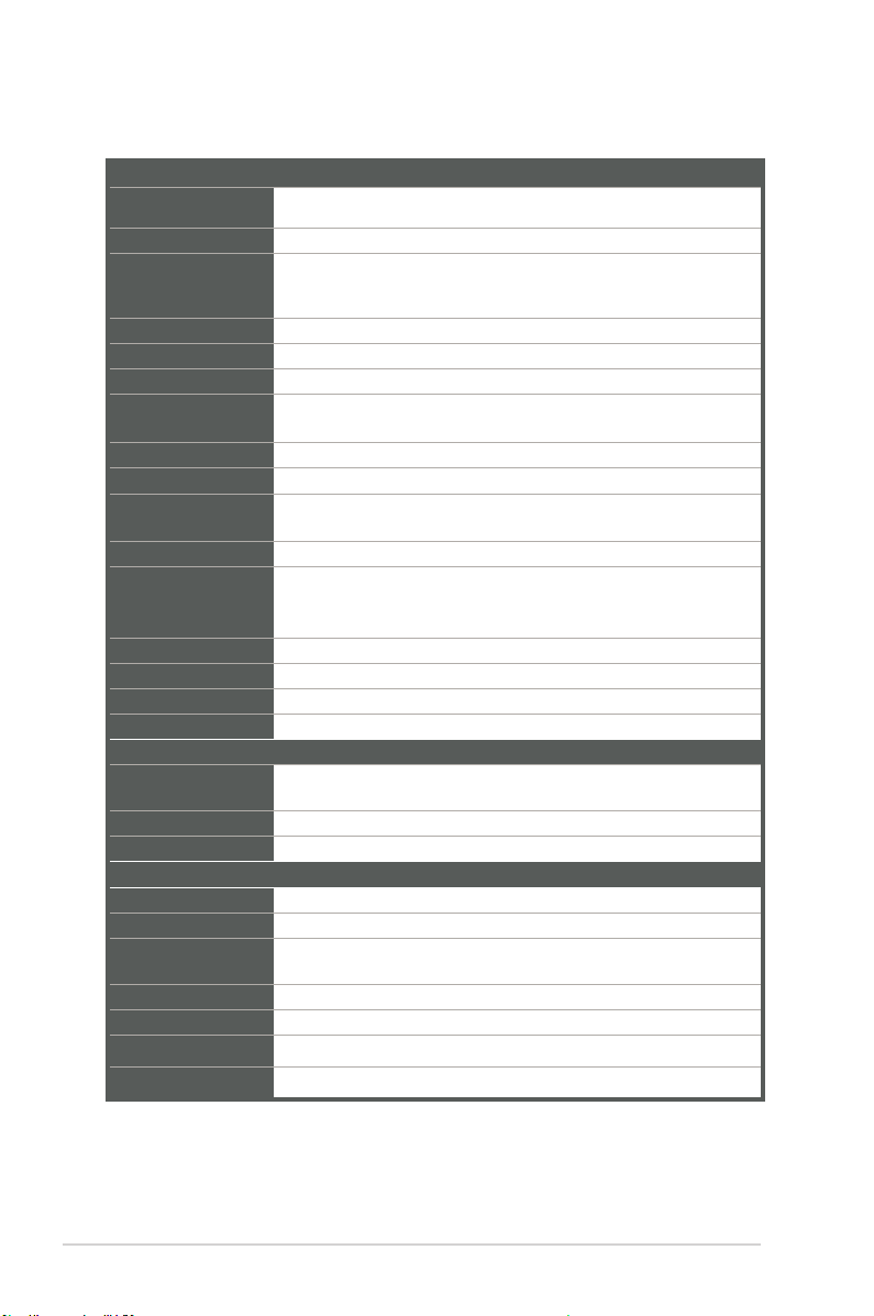
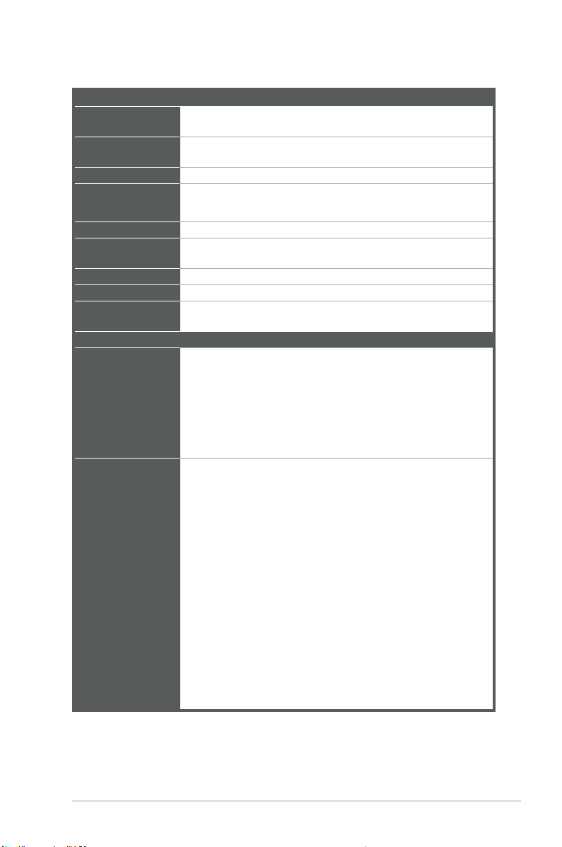
1.3 Specications............................................................................... 1-2
Chapter 2: Motherboard information
2.1 Before you proceed ..................................................................... 2-1
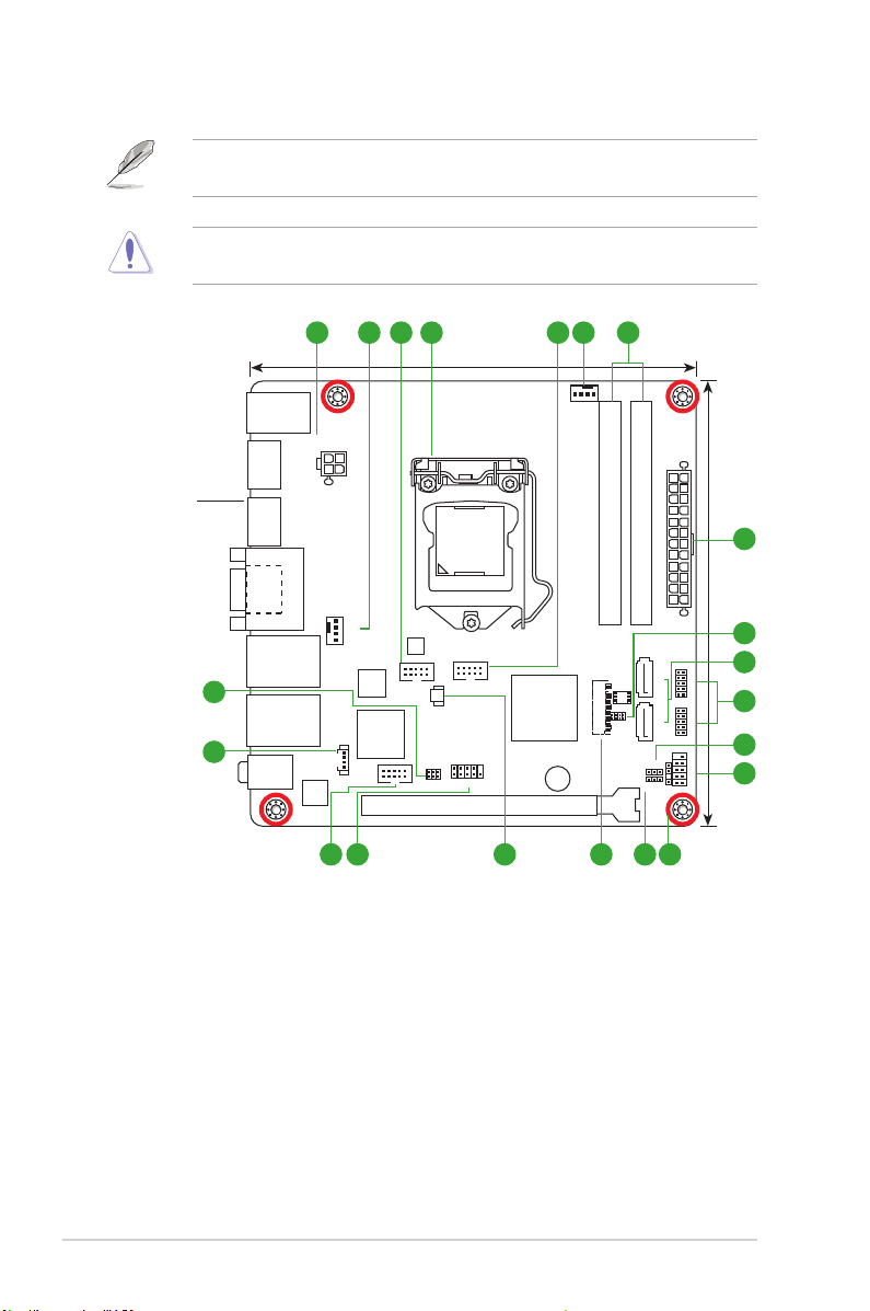
2.2 Motherboard layout...................................................................... 2-2
2.3 Screw size..................................................................................... 2-4
2.3.1 Component side.............................................................. 2-4
2.3.2 Solder side ...................................................................... 2-5
2.4 Central Processing Unit (CPU) ................................................... 2-6
2.4.1 Installing the CPU ........................................................... 2-7
2.4.2 CPU heatsink and fan assembly installation................... 2-9
2.5 System memory ......................................................................... 2-11
2.6 Jumpers ...................................................................................... 2-12
2.7 Connectors ................................................................................. 2-15
2.7.1 Rear panel connectors.................................................. 2-15
2.7.2 Internal connectors ....................................................... 2-16
Chapter 3: BIOS setup
3.1 BIOS setup.................................................................................... 3-1
3.2 Main menu .................................................................................... 3-2
3.2.1 System Date [Day MM/DD/YYYY] .................................. 3-2
3.2.2 System Time [HH:MM:SS] .............................................. 3-2
3.3 Advanced menu ........................................................................... 3-2
3.3.1 CPUConguration .......................................................... 3-2
3.3.2 Trusted Computing ......................................................... 3-3
3.3.3 SATAConguration ........................................................ 3-4
3.3.4 AMTConguration .......................................................... 3-4
3.3.5 PCH-FWConguration ................................................... 3-4
3.3.6 SIOConguration ........................................................... 3-5
3.3.7 NCT6791D HW Monitor .................................................. 3-5
3.3.8 USBConguration .......................................................... 3-7
3.3.9 DigitalIOPortConguration ........................................... 3-7
3.3.10 Power Management........................................................ 3-8

iv
3.4 Chipset menu ............................................................................... 3-9
3.4.1 SystemAgent(SA)Conguration ................................... 3-9
3.4.2 PCH-IOConguration ..................................................... 3-9
3.5 Security menu ............................................................................ 3-10
3.5.1 Administrator Password ................................................ 3-10
3.5.2 User Password.............................................................. 3-10
3.6 Boot menu .................................................................................. 3-11
3.6.1 BootConguration ........................................................ 3-11
3.6.2 Boot Option Priorities .................................................... 3-11
3.7 Save & Exit menu....................................................................... 3-12
Appendix
Notices.......................................................................................................A-1

1-1
Chapter 1: General information
1.1 Package contents
Check your industrial motherboard package for the following items.
1 x Industrial Motherboard
1 x SATA cable
1 x I/O Shield
1 x Support CD
If any of the above items is damaged or missing, contact your distributor or
sales representative immediately.
1.2 Features
• Intel®6th Generation Core™ i7/ i5 /i3, Pentium®LGA 1151 socket processor,
Max. 65W TDPs
• 2 x SO-DIMM, max. 32GB, 260-pin DDR4 2133/1867 MHz, Non-ECC, Un-
buffered Memory
• 2 x SATA 6.0 Gb/s, 4 x USB3.0, 6 x USB2.0
• Realtek®ALC887 with Amp.
• Multi Display: DP+DP, DP+VGA, DP+DP+VGA, DP+DP+DP
• Dual Ethernet LAN: 1 x Intel®PCIe Gb LAN 219LM for vPro, 1 x Intel®PCIe Gb
LAN 211AT
• 1 x PCIe [x16] slot, 1 x M.2 M-key slot (22 x 80mm) for PCIe x4 / SATA at the
bottom side
Chapter 1
Product overview

EMB-Q170A
1-2
1.3 Specications
(continued on the next page)
SYSTEM
CPU Intel®6th Generation Core™ i7 / i5 / i3, Pentium®LGA 1151 socket
processor, Max. 65W TDPs
Chipset Intel®Q170 Express Chipset
Memory 2 x SO-DIMMs, Max. 32GB, DDR4 2133/1867 MHz, Non-ECC (Vertical
Type)
Dual channel memory architecture
Graphics Chipset Intel®HD Graphics
I/O Chipset NCT6791D
Storage 2 x SATA 6.0Gb/s ports
LAN 1 x Intel®PCIe Gb LAN 219LM for vPro
1 x Intel®PCIe Gb LAN 211AT
Audio Realtek®ALC887 with Amp.
TPM InneonSLB9665TT2.0(optional,default:no)
Expansion slots 1 x PCIe [x16] slot (Gen 3)
1 x M.2 slot(M-key), 22 x 80mm(SATA, PCIe x4) at the bottom side
BIOS 128Mb Flash ROM, AMI BIOS
H/W Status Monitor Monitors CPU/system temperature
Monitors Vcore, 5V/12V voltages
Monitors CPU/chassis fan speed
Watchdog Timer 1~255 steps by software program
Smart Fan Control CPU Fan(3.3V/5V PWM control) / Chassis Fan
Wake On LAN / PXE Yes ( WOL, PXE)
Power States S3, S4, S5
Graphics
Graphics Multi
Display DP+DP, DP+VGA, DP+DP+VGA, DP+DP+DP
VGA Resolution Up to 1920 x 1200 @ 60 Hz
DP Up to 4096 x 2304 @ 60 Hz, with Digital Audio (Standard 1.2)
Environment, Power, and ME
Battery Lithium battery
Power requirement ATX
Operating
temperature 32oF~140oF (0oC~60oC)
Operating humidity 0%~90% relative humidity, non-condensing
Certicate CE/FCC, class A
Form factor Mini-ITX form factor:
6.7 in. x 6.7 in. (17.0 cm x 17.0 cm)
Weight 1.1 lb (0.5 Kg)

1-3
Chapter 1: General information
I/O
Storage
2 x SATA 6.0Gb/s, support RAID 0/1/5/10
1 x M.2 slot(M-key), 22 x 80mm (SATA, PCIe x4) at the bottom side
USB
4 x USB 3.0 ports (4 ports at the Rear I/O)
6 x USB 2.0 ports (2 ports at the Rear I/O, 4 ports at mid board)
Display I/O
1 x VGA, 3 x DP
Audio I/O
Mic-in, Line-out, 1 x internal speaker (When a headphone or a
speaker is plugged into the Line-out port, the internal speaker
becomes mute)
LAN I/O 2 x RJ-45 ports on rear I/O
Serial ports
1 x RS-232 (mid board)
1 x RS-232/422/485 supports 5V/12V/RI option (mid board)
PS/2 port
1 x Keyboard/mouse combo port
DIO 8-bit Digital I/O interface (4-in / 4-out)
Fan
1 x CPU Fan connector (4-pin)
1 x Chassis Fan connector (4-pin)
I/O Placement
Back panel I/O ports
1 x PS/2 keyboard/mouse combo port
2 x USB 2.0 ports
3 x DisplayPort
1 x VGA port
2 x LAN (RJ-45) ports
4 x USB 3.0 ports
1 x Audio jack (Line-Out), lime
1 x Audio jack (Mic-in), pink
Internal I/O
connectors
1 x PCIe [x16] slot
1 x M.2 slot(M-key), 22 x 80mm(SATA, PCIe x4) at the bottom side
2 x SATA 6.0 connectors
2 x USB 2.0 connectors support additional 4 USB ports (2.00mm)
2 x Boxer headers for COM (COM1: RS-232/422/485 supports 5V/12V/RI,
COM2: RS-232)
1 x Digital I/O connector (4-in / 4-out)
1 x 4-pin (2x2) internal power connector
1 x 24-pin EATX power connector
1 x 4-pin CPU Fan connector
1 x
4-pin
Chassis Fan connector
2 x System panel connectors (F_PANEL1, F_PANEL2)
1xInternalspeaker(2W/4Ω)
1 x Chassis intrusion jumper
1 x Onboard buzzer
1 x BIOS programmable connector
1 x AT/ATX mode selection jumper (default: No)
1 x CMOS jumper
(continued on the next page)

EMB-Q170A
1-4
Others
Supported OS Windows
®
7 32-bit / 64-bit (does not support xHCI and IDE)
Windows
®
8.1 64-bit
Windows
®
10 64-bit
Linux Fedora
Accessories 1 x SATA cable
1 x I/O shield
1 x Support DVD
NOTE: Specicationsaresubjecttochangewithoutnotice.

2-1
Chapter 2: Motherboard information
Chapter 2
Motherboard information
2.1 Before you proceed
Take note of the following precautions before you install motherboard components
or change any motherboard settings.
CAUTION!
• Unplugthepowercordfromthewallsocketbeforetouchingany
component.
• Beforehandlingcomponents,useagroundedwriststraportouchasafely
groundedobjectorametalobject,suchasthepowersupplycase,toavoid
damaging them due to static electricity.
• HoldcomponentsbytheedgestoavoidtouchingtheICsonthem.
• Wheneveryouuninstallanycomponent,placeitonagroundedantistatic
pad or in the bag that came with the component.
• Beforeyouinstallorremoveanycomponent,ensurethattheATXpower
supply is switched off or the power cord is detached from the power
supply.Failuretodosomaycauseseveredamagetothemotherboard,
peripherals,orcomponents.

EMB-Q170A
2-2
EMB-Q170A
EATX_PWR2
Super
I/O
CLRTC1
AT_ATX
17.0cm(6.7in)
17.0cm(6.7in)
EATX_PWR1
DDR4_DIMM_A1 (64bit, 260-pin module)
DDR4_DIMM_B1 (64bit, 260-pin module)
SATA6G_1
128Mb
BIOS
SATA6G_2
SPI_1
M.2(SOCKET3)
DP2
DP1 VGA1
DP3
KBMS_USB2_56
AUDIO1
LAN1_USB3_12
LAN2_USB3_34
F_PANEL1
F_PANEL2
USB78 USB910
CPU_FAN1
CHA_FAN1
DIO1
LAN
211AT
LAN
219LM
COM2
COM1
BATTERY1
LGA1151
PCIEX16_1
BZ1
COM1_V1
AMP_CON1
Intel®
Q170
ALC
887
2 64 51 2 3
9
10
8
7
11
1
15 14 1213115
17
16
CHASSIS1
2.2 Motherboard layout
Place this side
towards the rear
of the chassis
NOTE: Place four screws into the holes indicated by circles to secure the
motherboard to the chassis.
CAUTION!Donotovertightenthescrews!Doingsocandamagethe
motherboard.

2-3
Chapter 2: Motherboard information
Connectors/Jumpers/Slots Page
1. ATXpowerconnectors(24-pinEATXPWR1,4-pinEATX_PWR2) 2-16
2. CPUandchassisfanconnectors(4-pinCPU_FAN1,4-pinCHA_FAN1) 2-17
3. DigitalI/Oconnector(10-pinDIO1) 2-21
4. Intel® LGA1151CPUsocket 2-6
5. Serialportconnectors(10-pinCOM1~2) 2-20
6. DDR4SO-DIMMslots 2-11
7. BIOSprogrammableconnector(8-pinSPI_1) 2-21
8. SerialATA6.0Gb/sconnectors(7-pinSATA6G_1~2) 2-17
9. USB2.0connectors(10-pinUSB78andUSB910) 2-18
10. AT/ATXmodeselection(3-pinAT_ATX) 2-13
11. Systempanelconnectors(10-1pinF_PANEL1~2) 2-19
12. Chassisintrusionjumper(4-1pinCHASSIS1) 2-14
13. ClearRTCRAM(3-pinCLRTC1) 2-12
14. M.2M-Key(Bottom) 2-21
15. Batteryconnector(2-pinBATTERY1) 2-16
16. Speakeroutconnector(AMP_CON1) 2-18
17. COM1Ring/+5V/+12Vselection(COM1_V1) 2-13

EMB-Q170A
2-4
2.3 Screw size
2.3.1 Component side
170.18
170.18
15.59
38.43
60.43
85.93
83.91
148.59
29.40
99.31
104.09
126.09
161.01
112.00
146.53
121.15
5.21
16.15
84.95
83.55
92.42
120.46
133.92
109.20
126.60
57.02
125.48
153.67
152.78
149.61
152.27
150.50
0.00
34.37
14.32
10.92
18.74
32.39
10.49
6.75
84.58
123.83
137.67
149.35
160.83
165.08
79.95
59.63
45.45
52.01
77.72
113.41
142.24
71.85
0.00
31.57
12.09
32.09
54.09
79.59
107.59
129.59
148.59
170.18
31.57
0.00
151.77
159.77
165.35

2-5
Chapter 2: Motherboard information
2.3.2 Solder side
170.18
6.35
163.83
20.13
31.21
92.23
125.60
6.35
163.83
20.13
95.14
115.60
135.60
109.97
140.47
95.14
0.00
10.16
33.02
47.08
66.58
58.66
84.58
91.79
102.58
122.08
136.91
165.10 165.10
135.03
170.18
0.00

EMB-Q170A
2-6
2.4 Central Processing Unit (CPU)
ThismotherboardcomeswithanIntel®6thGenerationCore™i7/i5/i3,Pentium®
LGA1151socketprocessor.
IMPORTANT:UnplugallpowercablesbeforeinstallingtheCPU.
CAUTION!
• Uponpurchaseofthemotherboard,ensurethatthePnPcapison
thesocketandthesocketcontactsarenotbent.Contactyourretailer
immediatelyifthePnPcapismissing,orifyouseeanydamagetothe
PnPcap/socketcontacts/motherboardcomponents.Themanufacturerwill
shoulderthecostofrepaironlyifthedamageisshipment/transit-related.
• Keepthecapafterinstallingthemotherboard.Themanufacturerwill
processReturnMerchandiseAuthorization(RMA)requestsonlyifthe
motherboardcomeswiththecapontheLGA1151socket.
• Theproductwarrantydoesnotcoverdamagetothesocketcontacts
resultingfromincorrectCPUinstallation/removal,ormisplacement/loss/
incorrectremovalofthePnPcap.
EMB-Q170A
EMB-Q170A CPU socket LGA1151

2-7
Chapter 2: Motherboard information
2.4.1 Installing the CPU
1
A
B
2 3
CAUTION! EnsurethatyouinstallthecorrectCPUdesignedforLGA1151
only.DONOTinstallaCPUdesignedforLGA1155andLGA1156socketson
theLGA1151socket.

EMB-Q170A
2-8
A
B
C
4
5

2-9
Chapter 2: Motherboard information
2.4.2 CPU heatsink and fan assembly installation
CAUTION!ApplytheThermal
InterfaceMaterialtotheCPU
heatsinkandCPUbeforeyou
install the heatsink and fan if
necessary.
To install the CPU heatsink and fan assembly
B
A
A
B
1
2
3 4

EMB-Q170A
2-10
A
B
B
A
To uninstall the CPU heatsink and fan assembly
2
1

2-11
Chapter 2: Motherboard information
2.5 System memory
ThismotherboardcomeswithtwoDoubleDataRate4(DDR4)SmallOutlineDual
InlineMemoryModules(SO-DIMM)sockets.Thegureillustratesthelocationof
theDDR4SO-DIMMsockets:
Installing a DIMM
To install a SO-DIMM
EMB-Q170A
EMB-Q170A 260-pin DDR4 SO-DIMM sockets
DIMM_A1
DIMM_B1
1
B
A
B
B
AA
A
2
To remove a SO-DIMM

EMB-Q170A
2-12
2.6 Jumpers
1. Clear RTC RAM (3-pin CLRTC1)
ThisjumperallowsyoutocleartheRealTimeClock(RTC)RAMinCMOS.
YoucancleartheCMOSmemoryofsystemsetupparametersbyerasing
theCMOSRTCRAMdata.TheonboardbuttoncellbatterypowerstheRAM
datainCMOS,whichincludesystemsetupinformationsuchassystem
passwords.
To erase the RTC RAM:
1. TurnOFFthecomputerandunplugthepowercord.
2. Movethejumpercapfrompins1-2(default)topins2-3.Keepthecapon
pins2-3forabout5~10seconds,thenmovethecapbacktopins1-2.
3. PlugthepowercordandturnONthecomputer.
4. Holddownthe<Del>keyduringthebootprocessandenterBIOSsetup
to reenter data.
CAUTION!ExceptwhenclearingtheRTCRAM,neverremovethecapon
CLRTCjumperdefaultposition.Removingthecapwillcausesystemboot
failure!
NOTES:
• Ifthestepsabovedonothelp,removetheonboardbatteryandmovethe
jumperagaintocleartheCMOSRTCRAMdata.AfterclearingtheCMOS,
reinstall the battery.
• YoudonotneedtocleartheRTCwhenthesystemhangsdueto
overclocking.Forsystemfailureduetooverclocking,usetheCPU
ParameterRecall(C.P.R)feature.Shutdownandrebootthesystemsothe
BIOScanautomaticallyresetparametersettingstodefaultvalues.
EMB-Q170A
EMB-Q170A Clear RTC RAM
1 2 2 3
Normal
(Default)
Clear
RTC
CLRTC1
Table of contents
Other Aaeon Motherboard manuals

Aaeon
Aaeon IMBA-880 User manual

Aaeon
Aaeon EMB-LN9T Rev.B User manual

Aaeon
Aaeon Gene-6320 User manual

Aaeon
Aaeon PICO-BT01 User manual

Aaeon
Aaeon HSB-910I User manual

Aaeon
Aaeon IMBA-Q77 User manual

Aaeon
Aaeon GENE-HD05 User manual

Aaeon
Aaeon EMB-BT1 User manual

Aaeon
Aaeon MIX-Q370D1 User manual

Aaeon
Aaeon PICO-KBU4 User manual

Aaeon
Aaeon PICO-APL4 User manual

Aaeon
Aaeon EMB-945T User manual

Aaeon
Aaeon ITP11 User manual

Aaeon
Aaeon Raptor MicroATX User manual

Aaeon
Aaeon GENE-LN05 User manual

Aaeon
Aaeon IMBM-H81B User manual

Aaeon
Aaeon ECB-915A User manual

Aaeon
Aaeon EMB-APL1 User manual

Aaeon
Aaeon PCM-5893L User manual

Aaeon
Aaeon EMB-BT4 User manual