MSI 865GM2-LS - Motherboard - Micro ATX User manual

i
Version 1.1
G52-M6743X4
865GM2 / 865PEM2
MS-6743 (v1.X) Micro ATX Mainboard

ii
Manual Rev: 1.1
Release Date: May 2003
FCC-B Radio Frequency Interference Statement
This equipment has been tested and found to comply with the limits for a class
B digital device, pursuant to part 15 of the FCC rules. These limits are designed
to provide reasonable protection against harmful interference when the equip-
ment is operated in a commercial environment. This equipment generates, uses
and can radiate radio frequency energy and, if not installed and used in accor-
dance with the instruction manual, may cause harmful interference to radio
communications. Operation of this equipment in a residential area is likely to
cause harmful interference, in which case the user will be required to correct
the interference at his own expense.
Notice 1
The changes or modifications not expressly approved by the party respon-
sible for compliance could void the user’s authority to operate the equipment.
Notice 2
Shielded interface cables and A.C. power cord, if any, must be used in order to
comply with the emission limits.
VOIR LA NOTICE D’INSTALLATION AVANT DE RACCORDER AU
RESEAU.
Micro-Star International MS-6743
Tested to comply
with FCC Standard
For Home or Office Use

iii
Copyright Notice
The material in this document is the intellectual property of MICRO-STAR
INTERNATIONAL. We take every care in the preparation of this document,
but no guarantee is given as to the correctness of its contents. Our products
are under continual improvement and we reserve the right to make changes
without notice.
Trademarks
All trademarks are the properties of their respective owners.
AMD, Athlon™, Athlon™ XP, Thoroughbred™, and Duron™ are registered
trademarks of AMD Corporation.
Intel®and Pentium®are registered trademarks of Intel Corporation.
PS/2 and OS®/2 are registered trademarks of International Business Machines
Corporation.
Microsoft is a registered trademark of Microsoft Corporation. Windows®98/
2000/NT/XP are registered trademarks of Microsoft Corporation.
NVIDIA, the NVIDIA logo, DualNet, and nForce are registered trademarks or
trademarks of NVIDIA Corporation in the United States and/or other countries.
Netware®is a registered trademark of Novell, Inc.
Award®is a registered trademark of Phoenix Technologies Ltd.
AMI®is a registered trademark of American Megatrends Inc.
Kensington and MicroSaver are registered trademarks of the Kensington Tech-
nology Group.
PCMCIA and CardBus are registered trademarks of the Personal Computer
Memory Card International Association.
Revision History
Revision Revision History Date
V1.0 First release for PCB 1.x April 2003
V1.1 Add 1394 connetor May 2003
BIOS, add CPU Smart Fan
Temperature and CPU Fan
Tolerance Value

iv
1. Always read the safety instructions carefully.
2. Keep this User’s Manual for future reference.
3. Keep this equipment away from humidity.
4. Lay this equipment on a reliable flat surface before setting it up.
5. The openings on the enclosure are for air convection hence protects the
equipment from overheating. DO NOT COVER THE OPENINGS.
6. Make sure the voltage of the power source and adjust properly 110/220V
before connecting the equipment to the power inlet.
7. Place the power cord such a way that people can not step on it. Do not
place anything over the power cord.
8. Always Unplug the Power Cord before inserting any add-on card or module.
9. All cautions and warnings on the equipment should be noted.
10. Never pour any liquid into the opening that could damage or cause electri-
cal shock.
11. If any of the following situations arises, get the equipment checked by a
service personnel:
zThe power cord or plug is damaged.
zLiquid has penetrated into the equipment.
zThe equipment has been exposed to moisture.
zThe equipment has not work well or you can not get it work according
to User’s Manual.
zThe equipment has dropped and damaged.
zThe equipment has obvious sign of breakage.
12. DO NOT LEAVE THIS EQUIPMENT IN AN ENVIRONMENT
UNCONDITIONED,STORAGETEMPERATUREABOVE600
C(1400F),IT
MAY DAMAGE THE EQUIPMENT.
Safety Instructions
CAUTION: Danger of explosion if battery is incorrectly replaced.
Replace only with the same or equivalent type recommended by the
manufacturer.

v
CONTENTS
FCC-B Radio Frequency Interference Statement .......................................... iii
Copyright Notice .......................................................................................... iii
Revision History ........................................................................................... iii
Technical Support ......................................................................................... iii
Safety Instructions ....................................................................................... v
Chapter 1. Getting Started ........................................................................ 1-1
Mainboard Specifications .................................................................... 1-2
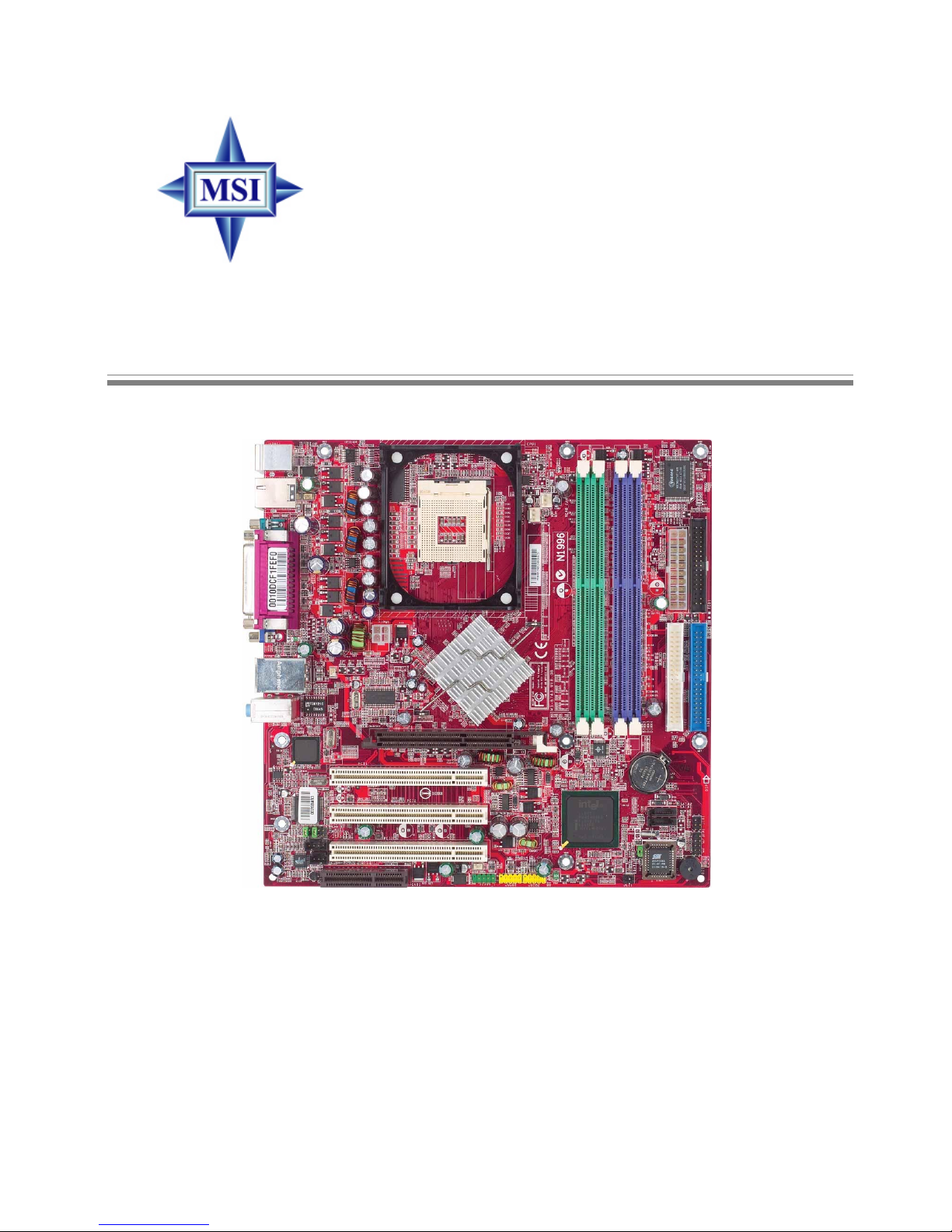
Mainboard Layout ............................................................................... 1-4
MSI Special Features ........................................................................... 1-5
Live BIOS™/Live Driver™ ............................................................ 1-5
Live Monitor™ .............................................................................. 1-6
PC Alert™ 4 ................................................................................... 1-7
Chapter 2. Hardware Setup ....................................................................... 2-1
Quick Components Guide .................................................................... 2-2
Central Processing Unit: CPU .............................................................. 2-3
CPU Core Speed Derivation Procedure ......................................... 2-3
CPU Installation Procedures for Socket 478 .................................. 2-4
Installing the CPU Fan .................................................................. 2-5
Memory ................................................................................................ 2-7
Introduction to DDR SDRAM ....................................................... 2-7
DIMM Module Combination ......................................................... 2-8
Installing DDR Modules ............................................................... 2-8
Power Supply ....................................................................................... 2-9
ATX 20-Pin Power Connector: ATX1 ............................................ 2-9
ATX 12V Power Connector: JPW1 ................................................ 2-9
Back Panel .......................................................................................... 2-10
Mouse Connector ....................................................................... 2-11
Keyboard Connector ................................................................... 2-11
RJ-45 LAN Jack (Optional) .......................................................... 2-12

vi
USB Connectors .......................................................................... 2-12
VGA Connector ........................................................................... 2-13
Audio Port Connectors ............................................................... 2-13
IEEE1394 Port (Optional) ............................................................ 2-14
Serial Port Connectors: COMA/B ................................................ 2-14
Parallel Port Connectors: LPT1 .................................................... 2-15
Connectors ......................................................................................... 2-16
Front Disk Drive Connector: FDD1 ............................................. 2-16
Hard Disk Connectors: IDE1 & IDE2 ........................................... 2-17
Fan Power Connectors: CPU_FAN/SYSTEM_FAN .................... 2-18
CD-In Connector: JCD1 ............................................................... 2-19
SPDIF Connector: JSPD1(Optional) ............................................ 2-19
IrDA Infrared Module Header: JIR1 (865PE only) ....................... 2-20
Chassis Intrusion Switch Connector: JCI1 .................................. 2-20
Front Panel Connector: JFP1 ....................................................... 2-21
Serial ATA Connectors: SATA1/SATA2 ..................................... 2-22
Front Panel Audio Connector: JAUD1 ........................................ 2-24
Front USB Connectors: JUSB1/JUSB2 ........................................ 2-25
IEEE 1394 Connector: J1394_1 ..................................................... 2-26
Jumpers .............................................................................................. 2-28
Clear CMOS Jumper: JBAT1 ........................................................ 2-28
Slots ................................................................................................... 2-29
AGP (Accelerated Graphics Port) Slots ....................................... 2-29
PCI (Peripheral Component Interconnect) Slots .......................... 2-29
CNR (Communication Network Riser) Slots ................................ 2-29
PCI Interrupt Request Routing .................................................... 2-30
Chapter 3. BIOS Setup .............................................................................. 3-1
Entering Setup ...................................................................................... 3-2
Control Keys ................................................................................. 3-2

vii
Getting Help .................................................................................. 3-3
The Main Menu ................................................................................... 3-4
Standard CMOS Features .................................................................... 3-6
Advanced BIOS Features .................................................................... 3-9
Advanced Chipset Features ............................................................... 3-13
Integrated Peripherals ........................................................................ 3-16
Power Management Setup ................................................................. 3-23
PNP/PCI Configurations ..................................................................... 3-27
PC Health Status ................................................................................ 3-29
Frequency/Voltage Control ................................................................ 3-31
Load High Performance/BIOS Setup Defaults .................................... 3-33
Set Supervisor/User Password ........................................................... 3-34
Appendix: Using 2-, 4- or 6-Channel Audio Function ............................... A-1
Installing C-Media Driver .................................................................... A-2
Hardware Configuration ...................................................................... A-4
Software Configuration ....................................................................... A-5
Using 2-, 4- or 6-Channel Audio Function ........................................ A-18
Troubleshooting ........................................................................................ T-1
Glossary .................................................................................................... G-1

1-1
Getting Started
Chapter 1. Getting
Started
Thank you for purchasing the MS-6743 v1.X M-ATX
mainboard. The MS-6743 is based on Intel®Springdale-G/PE
& Intel®ICH5 chipsets for optimal system efficiency. Designed
to fit the advanced Intel®Pentium 4 processor in the 478-pin
package, MS-6743 delivers a high performance and professional
desktop platform solution.
Getting Started

1-2
MS-6743 M-ATX Mainboard
Mainboard Specifications
CPU
hSupports Socket 478 for Intel®Pentium 4 (Socket 478) processor
hSupports 533MHz or 800MHz FSB
hSupports 3.06GHz or higher speed P4 processor
Chipsets
hIntel®Springdale-865G/865PE chipset
- Supports AGP 8x/4x at 0.8V (AGP 3.0) or 4x at 1.5V (not supports 3.3V)
- Integrated graphic controller (865G only)
- Supports 133/166/200MHz memory FSB
- Supports 400/533/800MHz Intel NetBurst micro-architecture bus.
hIntel®ICH5 chipset (421 mBGA)
- AC’97 2.3 interface
- 8 USB 2.0/1.1 ports
- 2 channel Ultra ATA/100 Bus Master IDE controller
- SMBus 2.0 support
- 2 serial ATA Host Controllers
- Integrated LAN controller
MainMemory
hSupports four 64-bit wide DDR data channels
hAvailable bandwidth up to 3.2GB/s (DDR 400) for single-channel mode
and 8.4 GB/s (DDR 400) for dual-channel mode
hSupports 128Mb, 256Mb or 512Mb DDR technologies
hSupports only x8, x16 DDR devices with 4-bank
Slots
hOne AGP supports 8x/4x at 0.8V (AGP 3.0) or 4x at 1.5V (not support 3.3V)
hThree PCI 2.2 32-bit Master PCI Bus slots.
hSupports 3.3v/5v PCI bus Interface.
hOne CNR slot
On-BoardIDE
hAn IDE controller on the ICH5 chipset provides IDE HDD/CD-ROM with
PIO, Bus Master and Ultra DMA66/100/133 operation modes.
hCan connect up to four IDE devices.

1-3
Getting Started
On-Board Peripherals
hOn-Board Peripherals include:
- 1 floppy port supports 2 FDD with 360K, 720K, 1.2M, 1.44M and 2.88
Mbytes.
- 1 serial port, 1 VGA port (865G) or 2 serial ports (865PE)
- 1 parallel port supports SPP/EPP/ECP mode
- 8 USB 2.0/1.1 ports (Rear * 4 / Front * 4)
- 1 Line-In/Line-Out/Mic
- 1 RJ45 connector (Optional)
- 2 1394 ports (Rear*1 / Front*1) (Optional)
Audio
hAC97 link controller integrated in ICH5
h6 channels software audio codec C-Media 9739A
- Compliant with AC97 v2.2 spec.
- Meet PC2001 audio performance requirement
- Can support SPDIF Out via bracket only
On-BoardLAN
hIntel 82562EZ
- Integrated 10/100 Ethernet MAC and PHY in one chip
- Supports 10Mb/s and 100Mb/s auto-negotiation operation
- Compliant with PCI v2.2, and LAN on Motherboard (LOM) standard
On-Board 1394
hNECPD72874
BIOS
hThe mainboard BIOS provides “Plug & Play” BIOS which detects the pe-
ripheral devices and expansion cards of the board automatically.
hThe mainboard provides a Desktop Management Interface (DMI) function
which records your mainboard specifications.
Dimension
hM-ATX Form Factor: 24.5 cm (L) x 24.5 cm (W)
Mounting
h6 mounting holes

1-4
MS-6743 M-ATX Mainboard
Mainboard Layout
MS-6743 v1.X M-ATX Mainboard
DDR1
DDR3
DDR2
DDR4
AGP Slot
T: mouse
B: keyboard
T:
Line-Out
B:Mic
Line-In
M:
JSPD1
CNR
JAUD1
JCD1
Codec
NEC
D72874GC
BATT
+
BIOS
Winbond
83627HF-AW
ICH5
Intel
Springdale
865PE/G
IDE1
IDE2
FDD1
PCI Slot 1
PCI Slot 2
PCI Slot 3
CPU_FAN
SYSTEM_FAN
JFP1
JIR1
JPW1
Intel
82562EZ
ATX
PowerSupply
J1394_1
JBAT1
JCI1
JUSB1
SATA2
SATA1
JUSB2

1-5
Getting Started
Live BIOS™/Live Driver™
The Live BIOS™/Live Driver™ is a tool used to detect and
update your BIOS/drivers online so that you don’t need to search
for the correct BIOS/driver version throughout the Web site. To
use the function, you need to install the “MSI Live Update 2”
application. After installation, the “MSI Live Update 2” icon (as
shown on the right) will appear on the screen.
Double click the “MSI Live Update 2” icon, and the follow-
ing screen will appear:
Five buttons are placed on the leftmost pane of the screen. Click the desired
button to start the update process.
zz
zz
zLive BIOS – Updates the BIOS online.
zz
zz
zLive Driver – Updates the drivers online.
zz
zz
zLive VGA BIOS – Updates the VGA BIOS online.
zz
zz
zLive VGA Driver – Updates the VGA driver online.
zz
zz
zLive Utility – Updates the utilities online.
If the product you purchased does not support any of the functions listed
above, a “sorry” message is displayed. For more information on the update
instructions, insert the companion CD and refer to the “Live Update Guide”
under the “Manual” Tab.
MSI Special Features

1-6
MS-6743 M-ATX Mainboard
Live Monitor™
The Live Monitor™ is a tool used to schedule the search
for the latest BIOS/drivers version on the MSI Web site. To use
the function, you need to install the “MSI Live Update 2”
application. After installation, the “MSI Live Monitor” icon (as
shown on the right) will appear on the screen. Double click this
icon to run the application.
Double click the “MSI Live Monitor” icon at the lower-right corner
of the taskbar, and the following dialog box will appear. You can specify how
often the system will automatically search for the BIOS/drivers version, or
change the LAN settings right from the dialog box.
You can right-click the MSI Live Monitor icon to perform the functions
listed below:
zz
zz
zAuto Search – Searches for the BIOS/drivers version you need immediately.
zz
zz
zView Last Result – Allows you to view the last search result if there is any.
zz
zz
zPreference – Configures the Search function, including the Search schedule.
zz
zz
zExit – Exits the Live Monitor™ application.
zz
zz
zFAQ – Provides a link to a database which contents various possible questions
about MSI's products for users to inquire.

1-7
Getting Started
PC Alert™ 4
The PC AlertTM 4 is a utility you can find in the CD-ROM disk. The utility
is just like your PC doctor that can detect the following PC hardware status
during real time operation:
Ømonitor CPU & system temperatures
Ømonitor fan speeds
Ømonitor system voltages
If one of the items above is abnormal, the program main screen will be
immediately shown on the screen, with the abnormal item highlighted in red.
This will continue to be shown until the condition returns to the normal status.
Users can use the Adjusting Keys to change the minimum and maximum
threshold of each item for the system to send out a warning message. Click
Temperature to select the temperature modes of either Fahrenheit (oF) or Cel-
sius (oC). The PC Alert™ 4 icon on the Status Area will show the current CPU
temperature.
Temperature
Modes
Adjusting Keys
COOLER XP

1-8
MS-6743 M-ATX Mainboard
To better protect the CPU from overheating, a new feature, COOLER
XP, has been added to decrease the temperature of AMD Athlon™ XP CPU.
To do so, simply click COOLER XP and the screen will show the Cute skin (as
shown below) with information about the CPU and chipset. Right-click the
mouse to select the skin you want to switch to.
Cute
MSI Reminds You...
1. The new feature COOLER XP will work only if your mainboard
supports AMD Athlon™ XP CPU.
2. Items shown on PC Alert 4 vary depending on your system’s
status.
3. Whenever the minimum or maximum threshold of each item has
been changed, please close the PC Alert 4 program for the new
settings to take effect.

2-1
Hardware Setup
Chapter 2. Hardware
Setup
This chapter tells you how to install the CPU, memory
modules, and expansion cards, as well as how to setup the jump-
ers on the mainboard. Also, it provides the instructions on con-
necting the peripheral devices, such as the mouse, keyboard,
etc.
While doing the installation, be careful in holding the com-
ponents and follow the installation procedures.
Hardware Setup

2-2
MS-6743 M-ATX Mainboard
Quick Components Guide
JCD1, p.2-19
JPW1, p.2-9 CPU, p.2-3
Back Panel
I/O, p.2-10
CPU_FAN1, p.2-18
FDD1, p.2-16
STAT2
SATA1, p.2-22
CNR1, p.2-29
JCI1, p.2-20
JSPD1, p.2-19
JFP1, p.2-21
JIR1, p.2-20
DDR DIMMs, p.2-7
ATX1, p.2-9
JAUD1, p.2-24
JUSB1, p.2-25
AGP slot, p.2-29
J1394_1, p.2-26
JBAT1, p.2-28
JUSB2, p.2-25
PCI slots, p.2-29
IDE1
IDE2, p.2-17
SYSTEM_FAN1, p.2-18

2-3
Hardware Setup
Central Processing Unit: CPU
CPU Core Speed Derivation Procedure
CPU Clock multiplied by Core/Bus ratio equals the CPU core speed.
For example:
If CPU Clock = 100MHz
Core/Bus ratio = 14
then CPU core speed = Host Clock x Core/Bus ratio
= 100MHz x 14
= 1.4 GHz
The mainboard supports Intel®Pentium®4/Celeron Northwood/Prescott
processor in the 478 pin package. The mainboard uses a CPU socket called
PGA478 for easy CPU installation. When you are installing the CPU, make
sure the CPU has a heat sink and a cooling fan attached on the top to
prevent overheating. If you do not find the heat sink and cooling fan, contact
your dealer to purchase and install them before turning on the computer.

2-4
MS-6743 M-ATX Mainboard
1. Please turn off the power and
unplug the power cord before
installing the CPU.
2. Pull the lever sideways away
from the socket. Make sure
to raise the lever up to a 90-
degree angle.
3. Look for the cut edge. The cut
edge should point towards the
lever pivot. The CPU can only
fit in the correct orientation.
4. If the CPU is correctly
installed, the pins should be
completely embedded into the
socket and can not be seen.
Please note that any violation
of the correct installation
procedures may cause
permanent damages to your
mainboard.
5. Press the CPU down firmly
into the socket and close the
lever. As the CPU is likely to
move while the lever is being
closed, always close the lever
with your fingers pressing
tightly on top of the CPU to
make sure the CPU is
properly and completely
embedded into the socket.
CPU Installation Procedures for Socket 478
Open Lever
Sliding
Plate
Dot / Cut edge
Close
Lever
Press down
the CPU
90 degree
Dot / Cut edge
Correct CPU placement
Dot / Cut edge
Incorrect CPU placement
X
O

2-5
Hardware Setup
Installing the CPU Fan
As processor technology pushes to faster speeds and higher performance,
thermal management becomes increasingly important. To dissipate heat, you
need to attach the CPU cooling fan and heatsink on top of the CPU. Follow
the instructions below to install the Heatsink/Fan:
2. Position the heatsink onto the reten-
tion mechanism.
1. Locate the CPU and its retention
mechanism on the motherboard.
3. Mount the fan on top of the heatsink.
Press down the fan until its four clips
get wedged in the holes of the reten-
tion mechanism.
4. Press the two levers down to fasten
the fan. Each lever can be pressed
down in only ONE direction.
retention mechanism
levers
This manual suits for next models
3
Table of contents
Other MSI Motherboard manuals

MSI
MSI K9A2GM User manual

MSI
MSI Z270I GAMING PRO CARBON AC User manual

MSI
MSI MPG X570 GAMING PLUS User manual

MSI
MSI MAG B550 TOMAHAWK User manual

MSI
MSI Z87-GD65 GAMING User manual

MSI
MSI P35 Diamond MS-7356 User manual

MSI
MSI B560-A PRO User manual

MSI
MSI MS-6182 User manual

MSI
MSI MEG Z390 GODLIKE User manual

MSI
MSI Z87 MPOWER MAX User manual

MSI
MSI K7T266Pro2-A User manual

MSI
MSI P45-8D Series User manual

MSI
MSI 945G Neo User manual

MSI
MSI MS-6114 User manual

MSI
MSI H170A GAMING PRO User manual

MSI
MSI X99A WORKSTATION User manual

MSI
MSI 7B93-001R User manual

MSI
MSI MEG B550 UNIFY User manual

MSI
MSI B450 GAMING PRO CARBON User manual

MSI
MSI MEG Z490I UNIFY User manual