MSI MS-6764 User manual

i
KT2 Combo
Version 1.0
G52-M6764X1-K01
MS-6764 (v1.X) ATX Mainboard

ii
Manual Rev: 1.0
Release Date: January 2003
FCC-B Radio Frequency Interference Statement
This equipment has been tested and found to comply with the limits for a class
B digital device, pursuant to part 15 of the FCC rules. These limits are designed
to provide reasonable protection against harmful interference when the equip-
ment is operated in a commercial environment. This equipment generates, uses
and can radiate radio frequency energy and, if not installed and used in accor-
dance with the instruction manual, may cause harmful interference to radio
communications. Operation of this equipment in a residential area is likely to
cause harmful interference, in which case the user will be required to correct
the interference at his own expense.
Notice 1
The changes or modifications not expressly approved by the party respon-
sible for compliance could void the user’s authority to operate the equipment.
Notice 2
Shielded interface cables and A.C. power cord, if any, must be used in order to
comply with the emission limits.
VOIR LA NOTICE D’INSTALLATION AVANT DE RACCORDER AU
RESEAU.
Micro-StarInternational MS-6764
Testedtocomply
withFCCStandard
ForHomeorOfficeUse

iii
CopyrightNotice
The material in this document is the intellectual property of MICRO-STAR
INTERNATIONAL. We take every care in the preparation of this document,
but no guarantee is given as to the correctness of its contents. Our products
are under continual improvement and we reserve the right to make changes
without notice.
Trademarks
All trademarks are the properties of their respective owners.
AMD, Athlon™, Athlon™ XP, Thoroughbred™, and Duron™ are registered
trademarks of AMD Corporation.
Intel®and Pentium®are registered trademarks of Intel Corporation.
PS/2 and OS®/2 are registered trademarks of International Business Machines
Corporation.
Microsoft is a registered trademark of Microsoft Corporation. Windows®98/
2000/NT/XP are registered trademarks of Microsoft Corporation.
NVIDIA, the NVIDIA logo, DualNet, and nForce are registered trademarks or
trademarks of NVIDIA Corporation in the United States and/or other countries.
Netware®is a registered trademark of Novell, Inc.
Award®is a registered trademark of Phoenix Technologies Ltd.
AMI®is a registered trademark of American Megatrends Inc.
Kensington and MicroSaver are registered trademarks of the Kensington Tech-
nology Group.
PCMCIA and CardBus are registered trademarks of the Personal Computer
Memory Card International Association.
Revision History
Revision Revision History Date
V1.0 First release with VIA®KT266A January 2003
&VIA® VT8235

iv
1. Always read the safety instructions carefully.
2. Keep this User’s Manual for future reference.
3. Keep this equipment away from humidity.
4. Lay this equipment on a reliable flat surface before setting it up.
5. The openings on the enclosure are for air convection hence protects the
equipment from overheating. Do not cover the openings.
6. Make sure the voltage of the power source and adjust properly 110/220V
before connecting the equipment to the power inlet.
7. Place the power cord such a way that people can not step on it. Do not
place anything over the power cord.
8. Always UnplugthePower Cordbeforeinsertingany add-oncardormodule.
9. All cautions and warnings on the equipment should be noted.
10. Never pour any liquid into the opening that could damage or cause electri-
cal shock.
11. If any of the following situations arises, get the equipment checked by a
service personnel:
zThe power cord or plug is damaged.
zLiquid has penetrated into the equipment.
zThe equipment has been exposed to moisture.
zThe equipment has not work well or you can not get it work according
to User’s Manual.
zThe equipment has dropped and damaged.
zThe equipment has obvious sign of breakage.
12. Do not leave this equipment in an environment unconditioned, storage
temperatureabove600C(1400F),itmaydamagetheequipment.
Safety Instructions
CAUTION: Danger of explosion if battery is incorrectly replaced.
Replace only with the same or equivalent type recommended by the
manufacturer.

v
CONTENTS
FCC-B Radio Frequency Interference Statement ...........................................ii
Copyright Notice ..........................................................................................iii
Revision History ........................................................................................... iii
Safety Instructions .......................................................................................iv
Chapter1.GettingStarted ........................................................................ 1-1
Mainboard Specifications .................................................................... 1-2
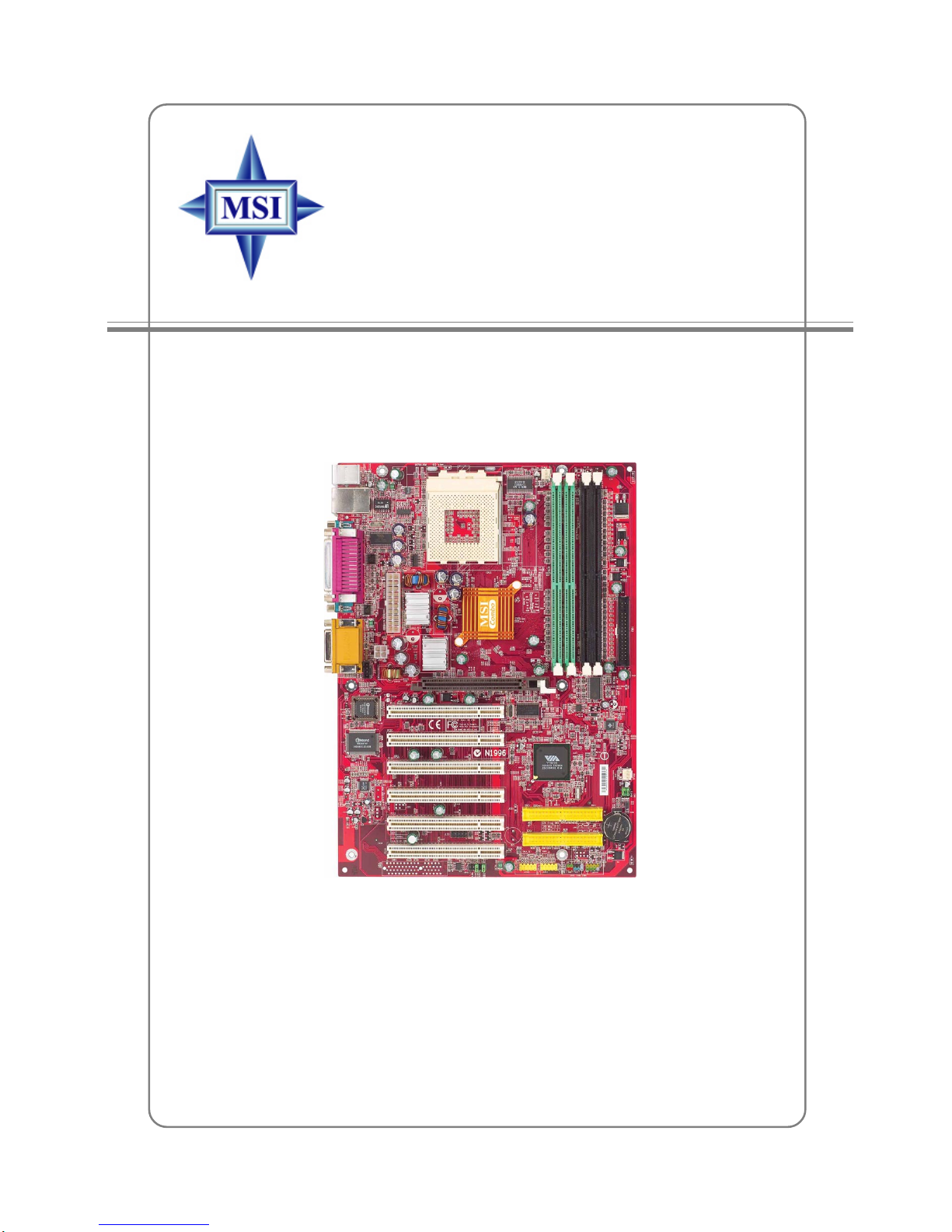
Mainboard Layout ...............................................................................1-4
MSI Special Features ...........................................................................1-5
FuzzyLogic™4 .............................................................................1-5
LiveBIOS™/LiveDriver™ ............................................................1-6
Live Monitor™ ..............................................................................1-7
D-Bracket(Optional) ..................................................................... 1-8
PCAlert™4 ................................................................................. 1-10
CPU Thermal Protection .............................................................. 1-12
Chapter2.HardwareSetup ....................................................................... 2-1
Quick Components Guide ....................................................................2-3
Central Processing Unit: CPU ..............................................................2-3
CPU Core Speed Derivation Procedure .........................................2-3
CPU Installation Procedures for Socket 462 ..................................2-4
Installing AMD Athlon CPU (Socket 462) Cooler Set ...................2-5
Memory................................................................................................2-6
Introduction to DDR SDRAM.......................................................2-6
DDR DIMM Module Combination ................................................2-7
Installing DDR Modules ...............................................................2-7
SDR DIMM Module Combination ................................................2-8
Installing SDR Modules ................................................................2-8
Power Supply .......................................................................................2-9
ATX 20-Pin Power Connector: JWR1 ............................................2-9
ATX 12V Power Connector: JPR1..................................................2-9

vi
BackPanel .......................................................................................... 2-10
Mouse Connector ....................................................................... 2-10
Keyboard Connector ................................................................... 2-11
USB 2.0 Connectors .................................................................... 2-11
Serial Port Connectors: COM A & COM B.................................. 2-12
RJ-45LANJack (Optional) .......................................................... 2-12
Parallel Port Connector: LPT1...................................................... 2-13
Joystick/Midi Connectors ........................................................... 2-14
Audio Port Connectors ............................................................... 2-14
Connectors......................................................................................... 2-15
Floppy Disk Drive Connector: FDD1........................................... 2-15
Hard Disk Connectors: IDE1 & IDE2 ........................................... 2-16
Fan Power Connectors: CPUFAN1/SYSFAN1 ............................. 2-17
CD-In Connector: J10 .................................................................. 2-18
Chassis Intrusion Switch Connector: J3...................................... 2-18
Front Panel Connectors: JFP1 & JFP2 ......................................... 2-19
Front Panel Audio Connector: JAUD1 ........................................ 2-20
D-BracketConnector:JLED......................................................... 2-21
Front USB Connectors: JUSB2/JUSB3 ........................................ 2-22
Jumpers .............................................................................................. 2-24
Clear CMOSJumper: JBAT1 ........................................................ 2-24
FSB Clock Override Jumper: SW3 ............................................... 2-25
Slots ................................................................................................... 2-26
AGP (Accelerated Graphics Port) Slot......................................... 2-26
PCI (Peripheral Component Interconnect) Slots.......................... 2-26
PCI Interrupt Request Routing .................................................... 2-27
Chapter3.BIOS Setup.............................................................................. 3-1
Entering Setup......................................................................................3-2
Selecting the First Boot Device .....................................................3-2

vii
Control Keys ................................................................................. 3-3
Getting Help ..................................................................................3-3
The Main Menu ...................................................................................3-4
Standard CMOS Features ....................................................................3-6
Advanced BIOS Features ....................................................................3-8
Advanced Chipset Features............................................................... 3-12
Power Management Features............................................................. 3-17
PNP/PCI Configurations..................................................................... 3-21
Integrated Peripherals ........................................................................ 3-23
PC Health Status ................................................................................ 3-27
Frequency/Voltage Control ................................................................ 3-28
Set Supervisor/User Password........................................................... 3-30
Load Optimal/High Performance Defaults .......................................... 3-31
Appendix:Using4-or6-ChannelAudioFunction ...................................A-1
Installing the Audio driver ..................................................................A-2
Using 4-/6- Channel Audio Function ..................................................A-4
Testing the connected speakers........................................................A-14
PlayingKaraOK ................................................................................A-16
Troubleshooting ........................................................................................ T-1
Glossary ....................................................................................................G-1

1-1
Getting Started
Chapter 1. Getting
Started
Thank you for purchasing KT2 Combo (MS-6764 v1.
X) ATX mainboard. The KT2 Combo is based on VIA®KT266A
&VT8235 chipsets and provides six USB 2.0 ports for high-
speed data transmission. Designed to fit the advanced AMD®
Athlon™,Athlon™ XPor Duron™ processors, the KT2 Combo
delivers a high performance and professional desktop platform
solution.
Getting Started

1-2
MS-6764 ATX Mainboard
Mainboard Specifications
CPU
hSupports Socket A (Socket-462) for AMD®Athlon™/Athlon™ XP /Duron™
processors.
hSupports 600MHz up to 2600+ MHz processor and higher.
Chipset
hVIA®KT266A chipset (522 BGA)
- FSB @200/266MHz.
- AGP 4X and PCI advanced high performance memory controller.
hVIA®VT8235 chipset (376 BGA)
- High Bandwidth V-link Client controller
- Integrated Faster Ethernet LPC
- Integrated Hardware Sound Blaster/Direct Sound AC97 audio
- Ultra DMA 66/100/133 master mode PCI EIDE controller
- Integrated USB2.0 Host Controller
- ACPI
MainMemory
hSupport two 184-pin unbuffered PC2100/PC1600 DDR SDRAM or two 168-
pin unbuffered PC100/133 SDRAM
hSupports up to 2GB memory size
Slots
hOne AGP (Accelerated Graphics Port) slot
- AGP specification compliant
- Supports AGP 2.0 4x
hSix 32-bit Master PCI Bus slots
hSupports 3.3V/5V PCI bus Interface
On-Board IDE
hAn IDE controller on the VIA® VT8235 chipset provides IDE HDD/CD-
ROM with PIO, Bus Master and Ultra DMA 66/100/133 operation modes
hCan connect up to 4 IDE devices
On-Board Peripherals
hOn-Board Peripherals include:
- 1 floppy port supports 2 FDDs with 360K, 720K, 1.2M, 1.44M and
2.88Mbytes

1-3
Getting Started
- 2 serial ports (COM A + COM B)
- 1 parallel port supports SPP/EPP/ECP mode
- 1 IrDA connector for SIR/ASKIR/HPSIR
- 1 audio/game port
- SPDIF output (1 x 3) with housing (Optional)
- 6 USB 2.0 ports (Rear * 2/ Front * 4)
Audio
hChip integrated (6-channel S/W audio)
- Direct Sound AC97 Audio
- 6-channel analog output
BIOS
hThe mainboard BIOS provides “Plug & Play” BIOS which detects the pe-
ripheral devices and expansion cards of the board automatically.
hThe mainboard provides a Desktop Management Interface (DMI) function
which records your mainboard specifications.
Dimension
hATX Form Factor: 30.4 cm (L) x 22 cm (W).
Mounting
h6 mounting holes.
Others
hSuspend to RAM/Disk (S3/S4).
hPC2001 compliant.
hVoltage independent adjustment in CPU, DDR, AGP.
hSupports DMI (Desktop Management Interface) through BIOS.
hSupports PCI 2.2.
hSuspends to RAM/Disk.

1-4
MS-6764 ATX Mainboard
Mainboard Layout
KT2 Combo (MS-6764 v1.X) ATX Mainboard
BATT
+
VT8235
VIA
KT266A
DDR1
DDR2
J3
ATX
PowerSupply
JAUD1
SOCKET 462
BIOS
PCI Slot 5
PCI Slot 6
PCI Slot 4
PCI Slot 3
PCI Slot 2
PCI Slot 1
SW3
JBAT1
JFP1 JFP2
JUSB2 JUSB3
JLED
T:LAN jack (Optional)
B:USB ports
Top : Parallel Port
Bottom:
COM A
COM B
Top : mouse
Bottom: keyboard
J10
CFAN1
JPW1
IDE 2
IDE 1
SFAN1
Winbond
W83697HF
Codec
Top :
Game port
Bottom:
Line-Out
Line-In
Mic
FDD1
AGP Slot
DIMM3
DIMM4

1-5
Getting Started
Features:
ØMSI Logo links to the MSI Web site
ØCPU Speed allows users to adjust the CPU speed through CPU
Multiplier and FSB
ØVoltage allows user to adjust the voltage of CPU/Memory/AGP
ØMSI Info provides information about the mainboard, BIOS and OS
ØCPU Info provides detailed information about the CPU
ØCPU Fan Speed shows the current running speed of CPU Fan
ØCPU Temp. shows the current CPU temperature
Fuzzy Logic™4
The Fuzzy Logic™ 4 utility is a user friendly tool that allows users to
view and adjust the current system status. To overclock the CPU FSB (Front
Side Bus) frequency under the Windows operating system, click FSB and use
the right and left arrow keys to select the desired FSB, and then click Apply to
apply the new setup value. To enable the system running at the specified FSB
every time when you click Turbo, click Save to save the desired FSB first. If
you want to know the maximal CPU overclocking value, click Auto to start
testing. The CPU FSB will automatically increase the testing value until the PC
reboots. After rebooting, click Turbo to apply the test result. Click Default to
restore the default values.
MSI Reminds You...
To adjust the options under CPU Speed and Voltage, use the right
and left arrow keys to select the desired value and then click Apply
to run the setup value.
MSI Special Features

1-6
MS-6764 ATX Mainboard
Live BIOS™/Live Driver™
The Live BIOS™/Live Driver™ is a tool used to detect
and update your BIOS/drivers online so that you don’t need
to search for the correct BIOS/driver version throughout the
whole Web site. To use the function, you need to install the
“MSI Live Update Series 2” application. After the installation,
the “MSI Live Update Series 2” icon (as shown on the right)
will appear on the screen.
Double click the “MSI Live Update Series 2” icon, and the following
screen will appear:
Five buttons are placed on the leftmost pane of the screen. Click the desired
button to start the update process.
ØLive BIOS – Updates the BIOS online.
ØLive Driver – Updates the drivers online.
ØLive VGA BIOS – Updates the VGA BIOS online.
ØLive VGA Driver – Updates the VGA driver online.
ØLive Utility – Updates the utilities online.
If the product you purchased does not support any of the functions listed
above, a “sorry” message is displayed. For more information on the update
instructions, insert the companion CD and refer to the “Live Update Series
Guide” under the “Manual” Tab.

1-7
Getting Started
You can right-click the MSI Live Monitor icon to perform the functions
listed below:
ØAuto Search – Searches for the BIOS/drivers version you need immediately.
ØView Last Result – Allows you to view the last search result if there is any.
ØPreference – Configures the Search function, including the Search schedule.
ØExit – Exits the Live Monitor™ application.
Live Monitor™
The Live Monitor™ is a tool used to schedule the search
for the latest BIOS/drivers version on the MSI Web site. To use
the function, you need to install the “MSI Live Update Series 2”
application. After the installation, the “MSI Live Monitor” icon
(as shown on the right) will appear on the screen. Double click
this icon to run the application.
Double click the “MSI Live Monitor” icon at the lower-right corner
of the taskbar, and the following dialog box will appear. You can specify how
often the system will automatically search for the BIOS/drivers version, or
change the LAN settings right from the dialog box.

1-8
MS-6764 ATX Mainboard
D-BracketTM2 Description
System Power ON
- The D-LED will hang here if the processor is damaged or
not installed properly.
Early Chipset Initialization
Memory Detection Test
- Testing onboard memory size. The D-LED will hang if
the memory module is damaged or not installed properly.
Decompressing BIOS image to RAM for fast booting.
Initializing Keyboard Controller.
Testing VGA BIOS
- This will start writing VGA sign-on message to the screen.
1 2
3 4
Red Green
D-Bracket™ 2
1 2
3 4
D-Bracket™ 2 (Optional)
D-Bracket™ 2 is an external USB bracket integrating four Diagnostic
LEDs, which use graphic signal display to help users understand their system.
The LEDs provide up to 16 combinations of signals to debug the system. The
4 LEDs can debug all problems that fail the system, such as VGA, RAM or
other failures. This special feature is very useful for the overclocking users.
These users can use the feature to detect if there are any problems or failures.
D-Bracket™ 2 supports both USB 1.1 & 2.0 spec.

1-9
Getting Started
D-BracketTM2 Description
Processor Initialization
- This will show information regarding the processor (like
brand name, system bus, etc…)
Testing RTC (Real Time Clock)
Initializing Video Interface
- This will start detecting CPU clock, checking type of video
onboard. Then, detect and initialize the video adapter.
BIOS Sign On
- This will start showing information about logo, processor
brand name, etc….
Testing Base and Extended Memory
- Testing base memory from 240K to 640K and extended
memory above 1MB using various patterns.
Assign Resources to all ISA.
Initializing Hard Drive Controller
- This will initialize IDE drive and controller.
Initializing Floppy Drive Controller
- This will initializing Floppy Drive and controller.
Boot Attempt
- This will set low stack and boot via INT 19h.
Operating System Booting
1 2
3 4

1-10
MS-6764 ATX Mainboard
PC Alert™ 4
The PC AlertTM 4 is a utility you can find in the CD-ROM disk. The utility
is just like your PC doctor that can detect the following PC hardware status
during real time operation:
Ømonitor CPU & system temperatures
Ømonitor fan speeds
Ømonitor system voltages
If one of the items above is abnormal, the program main screen will be
immediately shown on the screen, with the abnormal item highlighted in red.
This will continue to be shown until the condition returns to the normal status.
Users can use the Adjusting Keys to change the minimum and maximum
threshold of each item for the system to send out a warning message. Click
Temperature to select the temperature modes of either Fahrenheit (oF) or Cel-
sius (oC). The PC Alert4 icon on the Status Area will show the current CPU
temperature.
temperature
modes
Adjusting Keys
COOLER XP

1-11
Getting Started
MSI Reminds You...
The new feature COOLER XP will work only if your mainboard
supports AMD Athlon XP CPU.
Items shown on PC Alert 4 vary depending on your system’s status.
To better protect the CPU from overheating, a new feature, COOLER
XP, has been added to decrease the temperature of AMD Athlon XP CPU. To
do so, simply click COOLER XP and the screen will show the Cute skin (as
shown below) with information about the CPU and chipset. Right-click the
mouse to select the skin you want to switch to.
Cute

1-12
MS-6764 ATX Mainboard
CPU Thermal Protection
Aimed to prevent the CPU from overheating, MSI has developed a CPU
Thermal Protection mechanism for AMD Athlon™ XP CPU platform. This CPU
Thermal Protection mechanism works on a thermal signal sensor. If the
mechanism senses an abnormal temperature rise, it will automatically shut down
the system and the CPU temperature will then drop down and resume normal.
With this unique feature, users can better protect their CPU. Please note that
this feature is for AMD Athlon™ XP CPU only.

2-1
Hardware Setup
Chapter 2. Hardware
Setup
This chapter tells you how to install the CPU, memory
modules, and expansion cards, as well as how to setup the
jumpers on the mainboard. Also, it provides the instructions
on connecting the peripheral devices, such as the mouse,
keyboard, etc.
While doing the installation, be careful in holding the
components and follow the installation procedures.
Hardware Setup
Table of contents
Other MSI Motherboard manuals

MSI
MSI G31M2 Series User manual

MSI
MSI MEG X299 CREATION User manual

MSI
MSI MEG Z390 GODLIKE User manual

MSI
MSI PH67A-C45 Series User manual

MSI
MSI K9N6PGM-F - Motherboard - Micro ATX User manual

MSI
MSI RX480M2 MS-7093 User manual

MSI
MSI MAG B660 TOMAHAWK WIFI User manual

MSI
MSI KT4A-V User manual

MSI
MSI 645E Max-U User manual

MSI
MSI P35 Diamond MS-7356 User manual

MSI
MSI X370 XPOWER GAMING TITANIUM User manual

MSI
MSI K9NBPM2-FID Series User manual

MSI
MSI MS-98H7 User manual

MSI
MSI Z270 GAMING M5 User manual

MSI
MSI H510M PRO User manual

MSI
MSI MS-6198 User manual

MSI
MSI Z97 GAMING 3 User manual

MSI
MSI H170M BAZOOKA User manual

MSI
MSI MAG B460M MORTAR User manual

MSI
MSI B150M GAMING PRO User manual