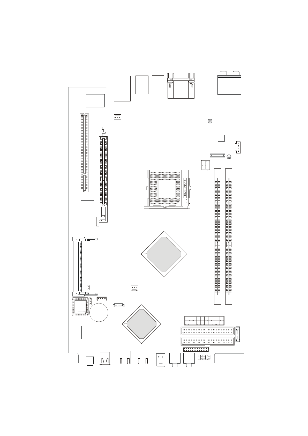
MSI MS-7072 User manual

i
MS-7072 Mainboard

ii
Copyright Notice
The material in this document is the intellectual property of MICRO-STAR
INTERNATIONAL. We take every care in the preparation of this document, but no
guarantee is given as to the correctness of its contents. Our products are under
continual improvement and we reserve the right to make changes without notice.
Trademarks
All trademarks are the properties of their respective owners.
AMD, Athlon™, Athlon™ XP, Thoroughbred™, and Duron™ are registered trade-
marks of AMD Corporation.
Intel®and Pentium®are registered trademarks of Intel Corporation.
PS/2 and OS®/2 are registered trademarks of International Business Machines
Corporation.
Microsoft is a registered trademark of Microsoft Corporation. Windows®98/2000/NT/
XP are registered trademarks of Microsoft Corporation.
NVIDIA, the NVIDIA logo, DualNet, and nForce are registered trademarks or trade-
marks of NVIDIA Corporation in the United States and/or other countries.
Netware®is a registered trademark of Novell, Inc.
Award®is a registered trademark of Phoenix Technologies Ltd.
AMI®is a registered trademark of American Megatrends Inc.
Kensington and MicroSaver are registered trademarks of the Kensington Technology
Group.
PCMCIA and CardBus are registered trademarks of the Personal Computer Memory
Card International Association.

iii
1. Always read the safety instructions carefully.
2. Keep this User’s Manual for future reference.
3. Keep this equipment away from humidity.
4. Lay this equipment on a reliable flat surface before setting it up.
5. The openings on the enclosure are for air convection hence protects the equip-
ment from overheating. Do not cover the openings.
6. Make sure the voltage of the power source and adjust properly 110/220V be-
fore connecting the equipment to the power inlet.
7. Place the power cord such a way that people can not step on it. Do not place
anything over the power cord.
8. Always Unplug the Power Cord before inserting any add-on card or module.
9. All cautions and warnings on the equipment should be noted.
10. Never pour any liquid into the opening that could damage or cause electrical
shock.
11. If any of the following situations arises, get the equipment checked by a service
personnel:
hThe power cord or plug is damaged.
hLiquid has penetrated into the equipment.
hThe equipment has been exposed to moisture.
hThe equipment has not work well or you can not get it work according to
User’s Manual.
hThe equipment has dropped and damaged.
hThe equipment has obvious sign of breakage.
12. Do not leave this equipment in an environment unconditioned, storage
temperature above 600 C (1400F), it may damage the equipment.
Safety Instructions
CAUTION: Danger of explosion if battery is incorrectly replaced.
Replace only with the same or equivalent type recommended by the
manufacturer.

Mainboard HardwareMainboard Hardware
Mainboard Hardware
1.1 Mainboard Layout1.1 Mainboard Layout
1.1 Mainboard Layout
1.2 CPU1.2 CPU
1.2 CPU1.2 CPU
1.2 CPU
1.3 Memory1.3 Memory
1.3 Memory
1.4 Power Supply1.4 Power Supply
1.4 Power Supply
1.5 Front Panel1.5 Front Panel
1.5 Front Panel
1.6 Back Panel1.6 Back Panel
1.6 Back Panel
1.7 Connectors1.7 Connectors
1.7 Connectors
1.8 Jumper1.8 Jumper
1.8 Jumper
1.9 Slots1.9 Slots
1.9 Slots1.9 Slots
1.9 Slots

1-2
Chapter 1
1.1Mainboardlayout
MS-7072 Mainboard
BATT
+
DIMM1 DIMM2
JCMOS
J1
JFP1
CN16
ATX
Power Supply
PCISlot1
MDCT2000
MHT2007
MHT2008
CNT2011
VIA
VT6307
RTL8100C
smsc
LPC47M997-NR
Codec
MINIPCI1
IDE2
IDE1 SATA1
JPW1
SYSFAN1
CPUFAN1
Top:COMPort
Bottom:VGAPort
Top:LANJack
Bottom:USBports
USBports
TV-out(S)connector
SPDIFIN1
AUDIO1
AUDIO2
USBT2003USBT2000
J1394-1 J1394-2
AGPSlot
T:
M:
B:
Line-In
Line-Out
Mic
T:RS-Out
M:CS-Out
B:SPDIFOut
ATI
Radeon
RS350
ATI
IXP300
SB300
BIOS CRT2000
JUSBT20001

1-3
Mainboard Hardware
1.2CPU
This mainboard supports Intel® P4 Northwood up to 3.2GHz and Prescott up to
3.4GHz. The mainboard uses a CPU socket called PGA478 for easy CPU installation.
When you are installing the CPU, make sure the CPU has a heat sink and a cooling fan
attached on the top to prevent overheating. Remember to peel off the sticker before
you install the CPU cooler. For information on how to install the CPU and cooler, refer
to Quick Installation Guide.
The mainboard provides 2 slots for 184-pin DDR SDRAM
DIMM (Double In-Line Memory Module) modules and supports the
memory size up to 2GB. You can install DDR400/DDR333/DDR266
modules into the DDR DIMM slots.
1.3 Memory
DIMM1 DIMM2
Note:
1. Read the instructions on the cooler before you start the installation.
2. Overheating will seriously damage the CPU and system, always make
sure the cooling fan can work properly to protect the CPU from overheating.
DIMM Module Combination
Install at least one DIMM module on the slots. You can install either single- or
double-sided modules in any order to meet your own needs. Memory modules can be
installed in any combination as follows:
S: Single Side
D: Double Side
Slot MemoryModule Total Memory
DIMM1 DDR S/D 64MB~1GB
(Bank 0 & 1)
DIMM2 DDR S/D 64MB~1GB
(Bank 2 & 3)
Maximum System Memory Supported 64MB~2GB

1-4
Chapter 1
1.4 Power Supply
The system is equipped with a 220W (PFC) ATX power supply. The power
cord of power supply has been connected to the connector ATX1 on the mainboard
when shipped out. Except the 20-pin connector ATX1, you can find another 4-pin
power connector JPW1 on the mainboard.
PIN SIGNAL
11 3.3V
12 -12V
13 GND
14 PS_ON
15 GND
16 GND
17 GND
18
19 5V
20 5V
PIN SINGAL
1 3.3V
2 3.3V
3 GND
45V
5 GND
65V
7 GND
8 PW_OK
9 5V_SB
10 12V
ATX1 Pin Definition
ATX1
20
10 1
11 1
3
4
2
JPW1
PIN SINGAL
1 GND
2 GND
3 12V
4 12V
JPW1 Pin Definition

1-5
Mainboard Hardware
1.5 Front panel
The Front Panel is independent and extended from the mainboard. It’s con-
nected to the Front I/O Connector on the mainboard. You can find the following ports
on the Front Panel.
IEEE 1394 Port: J1394-2
The mainboard provides two IEEE 1394 ports. This smaller one is designed
for you to connect the IEEE 1394 device with external power. The IEEE 1394 high-
speed serial bus complements USB by providing enhanced PC connectivity for a
wide range of devices, including consumer electronics audio/video (A/V) appliances,
storage peripherals, other PCs, and portable devices.
Software Support
IEEE 1394 Driver is provided by Windows®98 SE, Windows®XP, Win-
dows®ME and Windows®2000. Just plug in the IEEE 1394 connector into
the port. These Operating Systems will install the driver for IEEE 1394.
IEEE 1394 Port: J1394-1
The bigger 6-pin IEEE 1394 Port on the front panel is designed for you to
connect to IEEE 1394 devices without external power. That means the mainboard can
provide the power for the devices connected to this port.
Optical SPDIF-In Mic-InHead-Phone
USB x 2
J1394-1 J1394-2

1-6
Chapter 1
USB Ports
The mainboard provides a UHCI (Universal Host Controller Interface) Univer-
sal Serial Bus root for attaching USB devices such as keyboard, mouse or other
USB-compatible devices. You can plug the USB device directly into the connector.
PIN SIGNAL DESCRIPTION
1 VCC +5V
2 -Data 0 Negative Data Channel 0
3 +Data 0 Positive Data Channel 0
4 GND Ground
5 VCC +5V
6 -Data 1 Negative Data Channel 1
7 +Data 1 Positive Data Channel 1
8 GND Ground
USB Port Description
Mic-in/Head-Phone
Mic-in is a connector for stereo microphone. Head-Phone is a connector for
Speakers or Headphones.
OPTICAL SPDIF-in
The OPTICAL connector allows you to receive the audio file of SPDIF inter-
face for recording and playing.
The SPDIF (Sony & Philips Digital Interface) is developed jointly by the Sony
and Philips corporations. A standard audio file transfer format, SPDIF allows the
transfer of digital audio signals from one device to another without having to be
converted first to an analog format.

1-7
Mainboard Hardware
1.6 Back panel
The Back Panel provides the following ports:
Serial Port
The mainboard offers a 9-pin male DIN serial port. The port is 16550A high
speed communication ports that sends/receives 16 bytes FIFOs. You can attach a
serial mouse or other serial devices directly to the connector.
9-Pin Male DIN Connector
1 2 3 4 5
6 7 8 9
PIN SIGNAL DESCRIPTION
1 DCD DataCarryDetect
2 SIN SerialInorReceiveData
3 SOUT SerialOutorTransmitData
4 DTR DataTerminal Ready
5 GND Ground
6 DSR DataSetReady
7 RTS RequestToSend
8 CTS ClearToSend
9 RI RingIndicate
Pin Definition
VGA Port USB
CS-Out
SPDIF-Out
(optical)
RS-Out
Line-In
Mic-in
LAN Port
Serial Port
Line-Out

1-8
Chapter 1
VGAPort
The mainboard provides one DB 15-pin female connector to connect a VGA
monitor.
DB 15-Pin Female Connector
5 1
15 11
Pin Signal Description Pin Signal Description
1 RED 2 GREEN
3 BLUE 4 N/C
5 GND 6 GND
7 GND 8 GND
9 +5V 10 GND
11 N/C 12 SDA
13 HorizontalSync 14 VerticalSync
15 SCL
RJ45 LAN Jack
The mainboard provides one standard RJ-45 jack for connection to Local Area Net-
work (LAN). You can connect a network cable to the LAN jack.
Pin Definition
PIN SIGNAL DESCRIPTION
1 TDP TransmitDifferentialPair
2 TDN TransmitDifferentialPair
3 RDP ReceiveDifferential Pair
4 NC NotUsed
5 NC NotUsed
6 RDN ReceiveDifferentialPair
7 NC NotUsed
8 NC NotUsed

1-9
Mainboard Hardware
Audio Port Connectors
The left 3 audio jacks are for 2-channel mode for stereo speaker output: Line Out is
a connector for Speakers or Headphones. Line In is used for external CD player,
Tape player, or other audio devices. Mic is a connector for stereo microphone.
However, there is an advanced audio application provided by CMI9761A to offer
support for 5.1-channel audio operation and can turn rear audio connectors from
2-channel to 4-/5.1-channel audio.
Rear Speaker Out
(in 5.1CH)
Line Out
Line In
MIC
Center/Subwoofer Speaker Out
( in 5.1CH)
S/PDIF Out-Optical

1-10
Chapter 1
1.7 Connectors
IDE1 (Primary IDEConnector) - IDE1 can only connect a HDD.
IDE2 (Secondary IDE Connector) - IDE2 can only connect a CD-ROM drive.
IDE Connectors: IDE1 & IDE2
The mainboard has a 32-bit Enhanced PCI IDE and Ultra DMA 33/66/100 con-
troller that provides PIO mode 0~4, Bus Master, and Ultra DMA/33/66/100 function.
The two connectors on the mainboard allows you to connect to two IDE devices.
SerialATA Connector: SATA1
The mainboard provides the connector to connect the hard disk of Serial ATA
interface.
IDE1
IDE2
SATA1
Pin Definition
Pin Signal Pin Signal
1 GND TXP
3 TXN GND
5 RXN RXP
7 GND
2
4
6

1-11
Mainboard Hardware
Modem Module Connector: MDCT2000 (Optional)
The mainboard provides the connector to connect the modem module. The
modem module is directly inserted into the connector without an extra cable.
CPU Fan Connectors: CPUFAN1/SYSFAN1
The CPUFan1/SYSFAN1 connectors support system cooling fans with +12V
that is controlled by PWM. When connecting the wire to the three-pin head connectors,
always note that the red wire is the positive and should be connected to the +12V
(that is controlled by PWM), the black wire is Ground and should be connected to
GND.
Card Reader Connector: CRT2000
The mainboard provides a connector to connect the USB Card Reader (for
Deluxe Model) on the Front Panel.
MDCT2000
CRT2000
CPUFAN1
SENSOR
FAN Power
GND
SENSOR
FAN Power
GND
SYSFAN1

1-12
Chapter 1
Color LED Connector: LCMT2000
The connector is used to connect the color LED on the front panel.
Pin Definition
Pin Signal
1 SRS
5 MP_RTS
7 MP_DTR
9 IR or RST#
11 CD_SMI#
13 VCC5
15 MP_CTR_PWRON
17 IDE_LED
19 PLED1
21 PLED2
25 BASS_DETECT
Pin Signal
4 OS-SEL
6 MP_RXD
8 MP_TXD
10 FLAT
12 ROCK
14 POPS
16 CLASSIC
18 EQ_CYC
20 VCC5-SB
23 BASS
TV-Tuner Card Connector: CNT2011
The mainboard provides the connector to connect the TV-Tuner card. You
can insert the TV-Tuner card into the PCI Slot 1.
GND
R
LCNT2011
LCMT2000
125
26
2

1-13
Mainboard Hardware
1.8Jumper
There is a CMOS RAM on board that has a power supply from external
battery to keep the data of system configuration. With the CMOS RAM, the system
can automatically boot OS every time it is turned on. That battery has long life time for
at least 2 years. If you want to clear the system configuration, use the JBAT1 (Clear
CMOS Jumper ) to clear data. Follow the instructions below to clear the data:
Clear CMOS Jumper: JBAT1
Clear Data
1
3
Keep Data
1
3
JBAT1
You can clear CMOS by shorting 2-3 pin while the system is off. Then
return to 1-2 pin position. Avoid clearing the CMOS while the system is
on; it will damage the mainboard.

1-14
Chapter 1
1.9 Slots
AGP (Accelerated Graphics Port) Slot
The AGP slot allows you to insert theAGP graphics card. AGP is an interface
specification designed for the throughput demands of 3D graphics. It introduces a
66MHz, 32-bit channel for the graphics controller to directly access main memory and
provides 4x/8x throughputs.
PCI Slot
The PCI slot allows you to insert PCI card or TV Tuner card. When adding or
removing expansion cards, make sure that you unplug the power supply first.
Meanwhile, read the documentation for the expansion card to make any necessary
hardware or software settings.
Mini PCI
Mini PCI Slot
The motherboard provides a mini PCI slot for connecting a mini PCI interface
card.
AGPPCI

Setting BIOS FunctionSetting BIOS Function
Setting BIOS Function
2.1 Entering Setup2.1 Entering Setup
2.1 Entering Setup
2.2 The Main Menu2.2 The Main Menu
2.2 The Main Menu
2.3 Standard CMOS Features2.3 Standard CMOS Features
2.3 Standard CMOS Features
2.4 Advanced BIOS Features2.4 Advanced BIOS Features
2.4 Advanced BIOS Features
2.5 Advanced Chipset Features2.5 Advanced Chipset Features
2.5 Advanced Chipset Features
2.6 Integrated Peripherals2.6 Integrated Peripherals
2.6 Integrated Peripherals
2.7 Power Management Setup2.7 Power Management Setup
2.7 Power Management Setup
2.8 PnP/PCI Configurations2.8 PnP/PCI Configurations
2.8 PnP/PCI Configurations
2.9 PC Health Status2.9 PC Health Status
2.9 PC Health Status
2.10 Load Fail-Safe/Optimized Defaults2.10 Load Fail-Safe/Optimized Defaults
2.10 Load Fail-Safe/Optimized Defaults
2.11 Set Supervisor/User Password2.11 Set Supervisor/User Password
2.11 Set Supervisor/User Password

2-2
Chapter 2
2.1 Entering Setup
Power on the computer and the system will start POST (Power On
Self Test) process. When the message below appears on the screen, press
<DEL> key to enter Setup.
Press DEL to enter SETUP
If the message disappears before you respond and you still wish to
enter Setup, restart the system by turning it OFF and On or pressing the
RESET button. You may also restart the system by simultaneously press-
ing <Ctrl>, <Alt>, and <Delete> keys.
Control Keys
<↑> Move to the previous item
<↓> Move to the next item
<←> Move to the item in the left hand
<→> Move to the item in the right hand
<Enter> Select the item
<Esc> Jumps to the Exit menu or returns to the main
menu from a submenu
<-/PD> Decrease the numeric value or make changes
<+/PU> Increase the numeric value or make changes
<F7> Load Fail-Safe Defaults
<F6> Load Optimal Defaults
<F10> Save all the CMOS changes and exit

2-3
Setting BIOS Function
Getting Help
After entering the Setup menu, the first menu you will see is the
Main Menu.
Main Menu
The main menu lists the setup functions you can make changes
to. You can use the control keys ( ↑↓ )to select the item. The on-line
description of the highlighted setup function is displayed at the bottom
of the screen.
Sub-Menu
If you find a right pointer symbol (as
shown in the right view) appears to
the left of certain fields that means a
sub-menu containing additional op-
tions can be launched from this field.
You can use control keys (↑↓ ) to
highlight the field and press <Enter>
to call up the sub-menu. Then you can
use the control keys to enter values and move from field to field within
a sub-menu. If you want to return to the main menu, just press <Esc >.
8IDE Primary Master
8IDE Primary Slave
8IDE Secondary Master
8IDE Secondary Slave
General Help <F1>
The BIOS setup program provides a General Help screen. You
can call up this screen from any menu by simply pressing <F1>. The
Help screen lists the appropriate keys to use and the possible selections
for the highlighted item. Press <Esc> to exit the Help screen.
Table of contents
Other MSI Motherboard manuals

MSI
MSI 870S-C45 Series User manual

MSI
MSI Q35MDO v2 User manual

MSI
MSI H55M-ED55 Series User manual

MSI
MSI A520M PRO-C DASH User manual

MSI
MSI PRO B760-P WIFI User manual

MSI
MSI MEG X570S ACE MAX User manual

MSI
MSI ATX IR1 User manual

MSI
MSI H81M-P33 Series User manual

MSI
MSI C236A WORKSTATION User manual

MSI
MSI 915GLM4-F User manual

MSI
MSI MAG B660M MORTAR WIFI DDR4 User manual

MSI
MSI 745 Ultra User manual

MSI
MSI MS-98H5 User manual

MSI
MSI Z77 MPower series User manual

MSI
MSI Z170M MORTAR User manual

MSI
MSI PH67A-C45 Series User manual

MSI
MSI X299 TOMAHAWK User manual

MSI
MSI P6NGM series User manual

MSI
MSI B85M-E43 DASH User manual

MSI
MSI B365M PRO-VD User manual