MSI E7320 Master-S User manual

i
EnglishVersion
G52-S9152X1
MS-9152 (v1.X) ATX Server Board
E7320 Master Series

ii
Manual Rev: 1.0
Release Date: August 2004
FCC-A Radio Frequency Interference Statement
This equipment has been tested and found to comply with the limits for a class A digital
device, pursuant to part 15 of the FCC rules. These limits are designed to provide
reasonable protection against harmful interference when the equipment is operated
in a commercial environment. This equipment generates, uses and can radiate radio
frequency energy and, if not installed and used in accordance with the instruction
manual, may cause harmful interference to radio communications. Operation of this
equipment in a residential area is likely to cause harmful interference, in which case
the user will be required to correct the interference at his own expense.
Notice 1
The changes or modifications not expressly approved by the party responsible for
compliance could void the user’s authority to operate the equipment.
Notice 2
Shielded interface cables and A.C. power cord, if any, must be used in order to
comply with the emission limits.
VOIR LA NOTICE D’INSTALLATION AVANT DE RACCORDER AU RESEAU.
Micro-Star International
MS-9152
This device complies with Part 15 of the FCC Rules. Operation is subject to the
following two conditions:
(1) this device may not cause harmful interference, and
(2) this device must accept any interference received, including interference that may
cause undesired operation.

iii
Copyright Notice
The material in this document is the intellectual property of MICRO-STAR
INTERNATIONAL. We take every care in the preparation of this document, but no
guarantee is given as to the correctness of its contents. Our products are under
continual improvement and we reserve the right to make changes without notice.
Trademarks
All trademarks are the properties of their respective owners.
Intel®and Pentium®are registered trademarks of Intel Corporation.
PS/2 and OS®/2 are registered trademarks of International Business Machines
Corporation.
Windows®95/98/2000/2003/NT/XP are registered trademarks of Microsoft Corporation.
Netware®is a registered trademark of Novell, Inc.
Award®is a registered trademark of Phoenix Technologies Ltd.
AMI®is a registered trademark of American Megatrends Inc.
RevisionHistory
Revision Revision History Date
V1.0 First release August 2004
Technical Support
If a problem arises with your system and no solution can be obtained from the user’s
manual, please contact your place of purchase or local distributor. Alternatively,
please try the following help resources for further guidance.
Visit the MSI website for FAQ, technical guide, BIOS updates, driver updates,
and other information: http://www.msi.com.tw/program/service/faq/
faq/esc_faq_list.php

iv
1. Always read the safety instructions carefully.
2. Keep this User’s Manual for future reference.
3. Keep this equipment away from humidity.
4. Lay this equipment on a reliable flat surface before setting it up.
5. The openings on the enclosure are for air convection hence protects the equip-
ment from overheating. DO NOT COVER THE OPENINGS.
6. Make sure the voltage of the power source and adjust properly 110/220V be-
fore connecting the equipment to the power inlet.
7. Place the power cord such a way that people can not step on it. Do not place
anything over the power cord.
8. Always Unplug the Power Cord before inserting any add-on card or module.
9. All cautions and warnings on the equipment should be noted.
10. Never pour any liquid into the opening that could damage or cause electrical
shock.
11. If any of the following situations arises, get the equipment checked by a service
personnel:
hThe power cord or plug is damaged.
hLiquid has penetrated into the equipment.
hThe equipment has been exposed to moisture.
hThe equipment has not work well or you can not get it work according to
User’s Manual.
hThe equipment has dropped and damaged.
hThe equipment has obvious sign of breakage.
12. DONOTLEAVETHISEQUIPMENTINANENVIRONMENTUNCONDITIONED,STOR-
AGETEMPERATUREABOVE600 C(1400F),ITMAYDAMAGETHEEQUIPMENT.
Safety Instructions
CAUTION: Danger of explosion if battery is incorrectly replaced.
Replace only with the same or equivalent type recommended by the
manufacturer.

v
CONTENTS
FCC-A Radio Frequency Interference Statement .......................................................... ii
Copyright Notice ........................................................................................................... iii
Trademarks.................................................................................................................... iii
Revision History ............................................................................................................ iii
Technical Support.......................................................................................................... iii
Safety Instructions ........................................................................................................ v
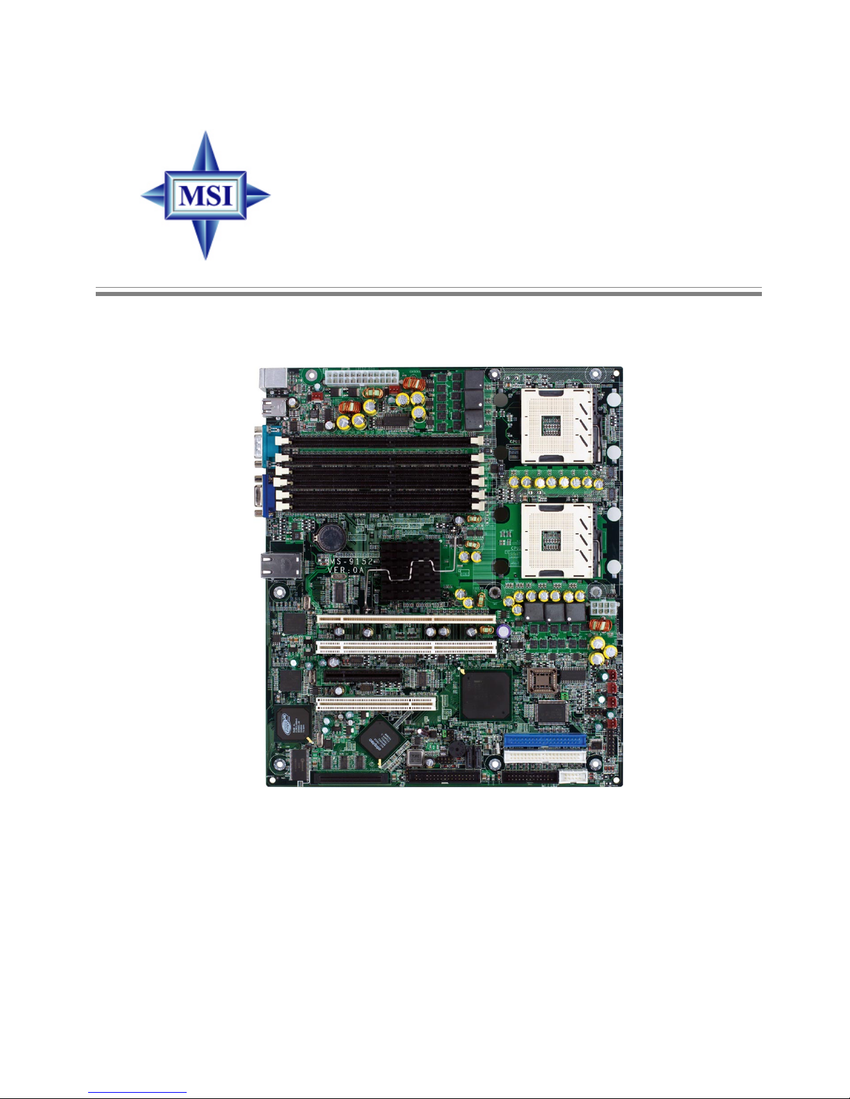
Chapter 1. Getting Started ....................................................................................1-1
Mainboard Specifications ................................................................................... 1-2
Mainboard Layout ............................................................................................... 1-5
MSI Special Features ..........................................................................................1-6
PCAlert™III ................................................................................................. 1-6
Chapter 2. Hardware Setup .................................................................................. 2-1
Quick Components Guide ...................................................................................2-2
Central Processing Unit: CPU.............................................................................. 2-3
CPU Installation Procedures for Socket 604 .............................................. 2-4
Installing the Intel CPU Cooler...................................................................... 2-5
Memory ...............................................................................................................2-6
Memory Bus Features ................................................................................2-6
Memory Population Rules............................................................................ 2-7
Memory Speed/CPU FSB Support Matrix ...................................................2-8
InstallingDDR Modules ................................................................................2-8
Power Supply .....................................................................................................2-9
SSI 24-Pin Power Connector: JPWR1.........................................................2-9
SSI 8-Pin Power Connector: JPWR2........................................................... 2-9
BackPanel.........................................................................................................2-10
Connectors ....................................................................................................... 2-11
Floppy Disk Drive Connector: JFDD........................................................... 2-11
Chassis Intrusion Switch Connector: JCI1 ............................................... 2-11
Fan Power Connectors: CPUFAN1/2/3, POWERFAN1/2/3/4.................... 2-11
Front USB Connector: JUSB1 ...................................................................2-12
ATA100 Hard Disk Connectors: IDE1 & IDE2 ............................................2-12
Serial ATA RAID 0, 1 Connectors: SATA1, SATA2 ...................................2-13
Serial Port Connector: COM 2 ...................................................................2-14
Front Panel Connector: JFP1 ....................................................................2-14
Ultra320 SCSI Connectors: SCSI1 (Optional) ...........................................2-15
SCSI LED Connector: J14 (Optional)........................................................2-15
LAN LED Connectors: J7 & J9...................................................................2-16
System Status LED Header: J11 ...............................................................2-16

vi
Redundancy Power SMBus Connector: J5 .............................................2-16
H/W Monitor SMBus Connector: J6 ..........................................................2-16
Parallel Port Header: CN11 ........................................................................2-17
Jumpers ............................................................................................................2-18
Clear CMOS Jumper: JBAT .......................................................................2-18
System Configure Jumper: J2...................................................................2-18
Slots ..................................................................................................................2-19
PCI (Peripheral Component Interconnect) Slots .......................................2-19
PCI Interrupt Request Routing ...................................................................2-19
Chapter 3. BIOS Setup ............................................................................................ 3-1
Entering Setup .................................................................................................... 3-2
Control Keys ...............................................................................................3-2
Getting Help ................................................................................................. 3-3
General Help <F1> ......................................................................................3-3
The Menu Bar .....................................................................................................3-4
Main .....................................................................................................................3-6
Advanced ...........................................................................................................3-9
Security.............................................................................................................3-16
Power ...............................................................................................................3-18
Boot ...................................................................................................................3-20
PCHealth...........................................................................................................3-21
Exit.....................................................................................................................3-23
Appendix A: SCSI BIOS Setup (Optional) .......................................................... A-1
EnteringSCSIBIOS ............................................................................................ A-2
Control Keys .............................................................................................. A-2
Selecting the SCSI Channel ....................................................................... A-2
Selecting the Management Type................................................................ A-2
Configure/View SCSI Controller Settings.......................................................... A-4
SCSI Bus Interface Definitions ................................................................... A-4
Additional Options ...................................................................................... A-5
BIOS Information ........................................................................................ A-8
DiskUtilities ........................................................................................................ A-8
Appendix B: Adaptec SATA RAID Utility for Intel ICH-HR (Optional) ............. B-1
Introduction ........................................................................................................ B-2
1. Overview ............................................................................................... B-2
2. Operating System Compatibility ............................................................. B-2
3. Storage Requirements ........................................................................... B-2
4. Features................................................................................................. B-2

vii
5. Storage Management Software Overview........................................... B-2
Installing the Driver............................................................................................. B-4
1. Installing the Driver in a New Windows System ................................... B-4
2. Installing the Driver in an Existing Windows System ............................ B-5
3. Installing Red Hat Linux 7.3 or 8.0 ......................................................... B-5
4. Installing SuSE Linux 8.0 or 8.1 ............................................................. B-6
Installing Adaptec Storage Manager – Browser Edition ................................... B-7
1. Overview ............................................................................................... B-7
2. Supported Browsers............................................................................. B-7
3. Typical, Custom, and Compact Installations........................................... B-7
4. Installing Adaptec Storage Manager on Windows ................................ B-8
5. Installing Adaptec Storage Manager on Linux ......................................B-11
Using Adaptec Storage Manager – Browser Edition ...................................... B-12
1. Overview ............................................................................................. B-12
2. Architecture Overview ........................................................................ B-13
3. Logging In ............................................................................................. B-13
4. Installing a Security Certificate ............................................................ B-14
5. Registering Your Software.................................................................. B-14
6. The Basics ........................................................................................... B-15
Adaptec RAID Configuration Utility .................................................................. B-19
1. Using the Array Configuration Utility.................................................... B-19
2. Using the Disk Utilities .......................................................................... B-22
Glossary .......................................................................................................... B-23

1-1
Getting Started
Thank you for choosing the E7320 Master Series (MS-9152 v1.
X) ATX server board. The E7320 Master Series are superior computer
mainboards based on Intel®Lindenhurst-VS & Hance Rapids
chipsets for optimal system efficiency. Designed to fit the advanced
Intel®XeonTM processors in the 604 pin package, the E7320 Master
Series provide a solution for front-end and general purpose server/
workstation in the entry-level and mid-range market segment.
Chapter 1. Getting
Started
Getting Started

1-2
MS-9152 ATX Server Board
Mainboard Specifications
CPU
hDual Intel®Xeon™ processors (800 MHz FSB) in Socket 604
h1MB/2MB L2 Cache
h6.4GB/s Trans Rate
Chipset
hIntel®Lindenhurst-VS MCH (Memory Controller Hub)
- Supports dual processors at 200 MHz (x4 transfers)
- System bus bandwidth of 6.4 GB/s
- Supports direct connect of two DDR channel interface, DDR 266/DDR 333 tech-
nology
hIntel®Hance Rapids ICH (I/O Controller Hub)
- Two port serial ATA controller
- Two channel Ultra ATA/100 bus master IDE controller
- One EHCI USB 2.0 host controller and two UHCI USB 1.1 host controllers(expanded
capabilities for four ports)
- PCI-X 1.0 interface
- PCI-2.2 interface
-I/OAPIC
- SMBus 2.0 controller
Memory Bus Feature
hSupport for up to six DDR-266, DDR-333 compliant registered ECC DIMM providing
up to 24GB (DDR266) of memory
hAvailable bandwidth up to 2.7GB/s (DDR333)
hSupport 128-Mb,256-Mb,512-Mb and 1Gb DDR technologies
Slots
hOne PCI (32-bit/33MHz) slot
hTwo PCI-X (64-bit/66MHz) slots
hOne PCI Express x8 slot (PCI Express Bus specification v1.0a compliant)
HDD Interface
hSCSI interface supported by Adaptec AIC-7901 Ultra-320 SCSI controller (Optional)
- Supports dual-channel Ultra320 LVD SCSI
hSerial ATA RAID interface supported by Intel®Hance Rapids ICH (with 2 SATA
connectors onboard/can connect up to 2 Serial ATA drives)
hUltra ATA/100 Bus Master IDE interface supported by Intel®Hance Rapids ICH (with
2 IDE connectors onboard/can connect up to 4 Ultra ATA drives)
Onboard Peripherals
hOn-Board Peripherals include:
- 1 floppy port supports 1 FDD with 360K, 720K, 1.2M, 1.44M and
2.88Mbytes

1-3
Getting Started
- 2 serial ports (COM1 & COM2)
- 1 VGA port
- 4 USB 2.0 ports (Rear * 2/ Front * 2)
- 2 RJ45 LAN jacks
Network
hBroadcom 5721 Gigabit Ethernet Controller (PCI-Express)
hBroadcom 5705 Gigabit Ethernet Controller (PCI)
Power Management Features
hWake up on LAN (WOL), USB, PCI, Mouse
hRTCalarm
hSupports ACPI S1, S4, and S5 functions
System Management
hMSI iConsole ASF
hSMBus (I2C)
hHardware monitoring
hThermal protection
hChassis intrusion
BIOS
h8MbitFlashEEPROM
hPCI 2.2 compliant, VPD, and DMI
hSMBIOS 2.3, ACPI 2.0
hSupports PXE boot protocol
hAPM 1.2, WOL, WOR
hPC2001 system design compliant
Dimension
hATX Form Factor: 12” x 10.16”
MSI Reminds You...
Enabling the functionality of Hyper-Threading Technology for your
computer system requires ALL of the following platform Components:
*CPU: Intel®Pentium®4 or Xeon™ Processors with HT Technology;
*Chipset: Intel®Chipsets that support HT Technology;
*BIOS: A BIOS that supports HT Technology and has it enabled;
*OS: An operating system that supports HT Technology.
For more information on Hyper-threading Technology, go to:
http://www.intel.com/info/hyperthreading

1-4
MS-9152 ATX Server Board
Mode Refresh Minimum Amount of Memory Required
rate(Hz)
640x480 60
640X480 72
640X480 75
640X480 90
640X480 100
800X600 60
800X600 70
800X600 75
800X600 90
800X600 100
1024X768 60
1024X768 72
1024X768 75
1024X768 90
1024X768 100
1280x1024 43
1280x1024 60
1280x1024 70
1280x1024 72
1600x1200 66
1600x1200 76
8bpp 16bpp 24bpp 32bpp
2MB 2MB 2MB 2MB
2MB 2MB 2MB 2MB
2MB 2MB 2MB 2MB
2MB 2MB 2MB 2MB
2MB 2MB 2MB 2MB
2MB 2MB 2MB 4MB
2MB 2MB 2MB 4MB
2MB 2MB 2MB 4MB
2MB 2MB 2MB 4MB
2MB 2MB 2MB 4MB
2MB 2MB 4MB 4MB
2MB 2MB 4MB 4MB
2MB 2MB 4MB 4MB
2MB 2MB 4MB 4MB
2MB 2MB 4MB 4MB
2MB 4MB 4MB 6MB
2MB 4MB 4MB 6MB
2MB - 4MB 6MB
2MB - 4MB 6MB
4MB 4MB 6MB 8MB
4MB 4MB 6MB -
Table 1. 2D Modes (TFT or CRT)
Shading indicates modes not supported by TFT
Video
hIntegrated ATI Rage XL graphics controller
- Built-in DVD decoding
- Integrated TMDS transmitter with support for Digital Flat Panel (DFP) monitors
- Onboard 8MB Video SDRAM
MSI Reminds You...
Please refer to Table 1 for 2D modes supporting both CRT and LCD.
The table specifies the minimum memory requirements for various
display resolutions, refresh rates and color depths.

1-5
Getting Started
Mainboard Layout
E7320 Master Series (MS-9152 v1.X) ATX Server Board
CPU1
CPU2
JPWR1
BATT
+
Intel
Lindenhurst-VS
PCIX1
PCIX2
USB
Ports
T: Mouse
B: Keyboard
LANCOM1
VGA1
JPWR2
POWERFAN1
PCI E1
PCI 1
IDE2
IDE1
CN11
JFDD
JFP1
JUSB1
J7
J9
J11
SATA1
SATA2
CPUFAN2
CPUFAN3
POWERFAN2
POWERFAN3
POWERFAN4
BIOS
SCSI 1
JBAT
J10
J2
J1
J13
JC11
COM2
mPGA604mPGA604
J5
CPUFAN1
J12
J14
J6
DIMM4
DIMM2
DIMM1
DIMM5
DIMM3
DIMM6

1-6
MS-9152 ATX Server Board
MSI Special Features
PC Alert™ III
The PC AlertTM III is a utility you can find in the CD-ROM disk. The utility is just like
your PC doctor that can detect the following PC
hardware status during real time operation:
Ømonitor CPU & system temperatures
Ømonitor fan speed(s)
Ømonitor system voltage
Ømonitor chassis intrusion
If one of the items above is abnormal, the
program main screen will be immediately shown
on the screen, with the abnormal item highlighted
in red. This will continue to be shown until user
disables the warning.
MSI Reminds You...
Items shown on PC Alert™ III vary depending on your system status.

2-1
Hardware Setup
Chapter 2. Hardware
Setup
Hardware Setup
This chapter provides you with the information about hard-
ware setup procedures. While doing the installation, be careful in
holding the components and follow the installation procedures. For
some components, if you install in the wrong orientation, the compo-
nents will not work properly.
Use a grounded wrist strap before handling computer
components. Static electricity may damage the components.

2-2
MS-9152 ATX Server Board
Quick Components Guide
BIOS
mPGA604mPGA604
CPU, p.2-3
JPWR1, p.2-9
CPUFAN1, p.2-11
Back Panel
I/O, p.2-10
IDE2/1,
p.2-12
DIMM1~6, p.2-6
CPUFAN2/3,
POWERFAN2/
3/4, p.2-11
PCI Slots,
p.2-19
JCI1, p.2-11
SCSI1, p.2-15 JUSB1,
p.2-12
JFP1, p.2-14
J7/9/11,
p.2-16
CN11, p.2-17
JBAT, p.2-18
J14, p.2-15
SATA1/2,
p.2-13
COM2, p.2-14
POWERFAN1, p.2-11
JFDD, p.2-11
JPWR2, p.2-9
J5/6, p.2-16
J2, p.2-18

2-3
Hardware Setup
The mainboard supports Single/Dual Intel®Xeon™ processor(s). The
mainboard uses two CPU sockets called Socket 604 for easy CPU installation. You
can install SINGLE or DUAL CPUs on the board to meet your own needs. Keep the
following points in mind before installing CPU(s):
1. If SINGLE CPU is intended, always install the CPU on the CPU1 socket.
2. To install DUAL CPUs on the board, you must use the same type of CPUs
running at the same FSB frequency.
When you are installing the CPU, make sure the CPU has a Heat Sink and
a cooling fan attached on the top to prevent overheating. If you do not find the
Heat Sink and cooling fan, contact your dealer to purchase and install them before
turning on the computer.
Central Processing Unit: CPU
MSI Reminds You...
Overheating will seriously damage the CPU and system, always make
sure the cooling fan can work properly to protect the CPU from
overheating.
The system temperature needs to remain under 45°C.
We highly recommend that the direction of inlet air should follow the
direction indicated above for better cooling effect.
Replacing the CPU
While replacing the CPU, always turn off the SSI power supply or
unplug the power supply’s power cord from grounded outlet first to
ensure the safety of CPU.
BIOS
mPGA604mPGA604
CPU1
Recommended inlet air
direction

2-4
MS-9152 ATX Server Board
1. Please turn off the power and
unplug the power cord before
installing the CPU.
2. Pull the lever sideways away
from the socket. Make sure to
raise the lever up to a 170-de-
gree angle.
3. Look for the gold arrow. The gold
arrow should point towards the
lever pivot. The CPU can only fit
in the correct orientation.
4. If the CPU is correctly installed,
the pins should be completely
embedded into the socket and
can not be seen. Please note
that any violation of the correct
installation procedures may
cause permanent damages to
your mainboard.
5. Press the CPU down firmly into
the socket and close the lever.
As the CPU is likely to move while
the lever is being closed, al-
ways close the lever with your
fingers pressing tightly on top of
the CPU to make sure the CPU is
properly and completely embed-
ded into the socket.
CPU Installation Procedures for Socket 604
Open Lever
Sliding
Plate
Gold arrow
Gold arrow
Gold arrow Correct CPU placement
Incorrect CPU placement
X
O
Close
Lever Press down
the CPU

2-5
Hardware Setup
Installing the Intel CPU Cooler
CPU cooler backplates
6. Screw to secure the CPU cooler.
5. Connect the CPU fan power cord to
CPUFAN1.
Note: If dual processors are installed,
connect the second CPU fan power
cord to CPUFAN2.
1. Flip over the mainboard and locate the position of the CPU sockets.
2. Stick the backplates to the back of the CPU sockets with holes aligned.
3. Install the CPU(s) following the in-
structions on page 2-4.
4. Apply some heat paste all over the
top of the CPU and place the cooler
onto it.

2-6
MS-9152 ATX Server Board
Memory
The mainboard provides 6 slots for 184-pin DDR DIMM (Double In-Line Memory
Module) modules. You can install PC2100/DDR266 or PC2700/DDR333 DDR SDRAM
modules on the DDR DIMM slots (DIMM 1~6).
Memory Bus Features
Support for direct connect of two DDR channel interfaces, DDR266/DDR333 tech-
nology
Full operation support in single channel mode on either interface
Stacked or unstacked DIMM support for registered DDR266 technology(up to four
DIMMs per channel)
Stacked or unstacked DIMM support for registered DDR333 technology(up to
three DIMMs per channel)
144-bit wide with ECC, DDR266/DDR333 memory interface supports x72, ECC,
registered DDR266/DDR333 DIMMs (using 128 Mb, 256 Mb, 512Mb, and 1 Gb)
Maximum 16 GB support with DDR333 up to two stacked DIMMs (1 Gb x 4 DRAMs)
Maximum 24 GB support with DDR266 up to two stacked DIMMs (1 Gb x 4 DRAMs)
Data bandwidth per channel 2.13 GB/s (DDR266) / 2.7 GB/s (DDR333)
Support for S4EC/D4ED (144,128) x4, Intel x4 Single Device Data Correction (x4
SDDC) ECC in dual channel mode
Support SEC/DED (72,64) ECC on each channel when Intel Single Device Data
Correction (SDDC) is disabled
D
I
M
M
6
B1
D
I
M
M
5
A1
D
I
M
M
4
B2
D
I
M
M
3
A2
D
I
M
M
1
A3
D
I
M
M
2
B3
CKE: 0/1 2/3 4/5
0/1 2/3 4/5
0/0# 2/2#
1/1# 1/1# 2/2#
0/0#
Clock:
C/S: 0/1 4/5 4/5
0/1 2/3 2/3
SPD: A8h AAh ACh
A0h A2h A4h
MCH

2-7
Hardware Setup
Memory Population Rules
The mainboard supports both single- & dual-channel modes. Install at least one
DIMM module on the slots. You can install either single- or double-sided modules to
meet your own needs. In dual-channel mode, make sure that you install memory
modules of the same type and density on DDR DIMMs “in pairs” -- {DIMM1 &
DIMM2}, {DIMM3 & DIMM4}.
Memory modules can be installed in any combination as follows:
DDR333 DIMM Population Rules
DDR266 DIMM Population Rules
DIMM Configuration DIMM 1 DIMM 2 DIMM 3 DIMM 4 DIMM 5 DIMM 6
1 Single Rank Single Single X X X X
1 Dual Rank Dual Dual X X X X
2 Single Ranks Single Single Single Single X X
1 Dual Rank, 1 Single Rank Single Single Dual Dual X X
2 Dual Ranks Dual Dual Dual Dual X X
3 Single Ranks Single Single Single Single Single Single
1 Dual Rank, 2 Single Ranks Single Single Single Single Dual Dual
2 Dual Ranks, 1 Single Rank Single Single Dual Dual Dual Dual
3 Dual Ranks Dual Dual Dual Dual Dual Dual
DIMM Configuration DIMM 1 DIMM 2 DIMM 3 DIMM 4 DIMM 5 DIMM 6
1 Single Rank Single Single X X X X
1 Dual Rank Dual Dual X X X X
2 Single Ranks Single Single Single Single X X
1 Dual Rank, 1 Single Rank Single Single Dual Dual X X
2 Dual Ranks Dual Dual Dual Dual X X
3 Single Ranks Single Single Single Single Single Single
1 Dual Rank, 2 Single Ranks Single Single Single Single Dual Dual
This manual suits for next models
2
Table of contents
Other MSI Server Board manuals

MSI
MSI 5500 Master Series User manual

MSI
MSI MS-91E2 User manual

MSI
MSI K9ND Speedster2 Series User manual

MSI
MSI E7210 Master-FARM User manual

MSI
MSI 945GC Network User manual

MSI
MSI MS-96E3 User manual

MSI
MSI E7320 Master-2S User manual

MSI
MSI MS-S2381 User manual

MSI
MSI E7520 Master2-S2M User manual

MSI
MSI MS-S0131 User manual

MSI
MSI 5520 Master Series User manual

MSI
MSI MS-S0101 User manual

MSI
MSI E7230 Master-FA4R User manual

MSI
MSI MS-S0131 User manual

MSI
MSI 5000V Master-A6 User manual

MSI
MSI 5000P Master2 Series User manual

MSI
MSI K9ND Speedster User manual

MSI
MSI MS-S0221 User manual

MSI
MSI E7210 MasterX-FA2R User manual

MSI
MSI MS-96D9 User manual