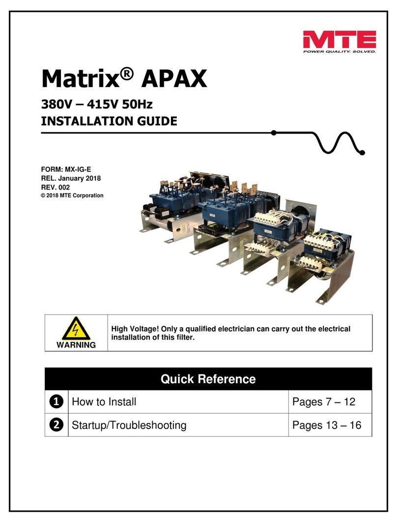
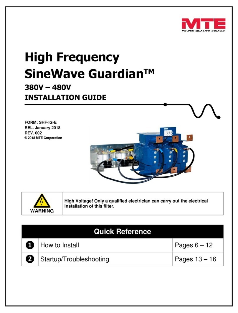
MTE Matrix E-Series Product manual

Matrix®E-Series
380V – 480V
TECHNICAL REFERENCE MANUAL
WARNING
High Voltage! Only a qualified electrician can carry out the electrical
installation of this filter.
Quick Reference
❶
Performance Data Pages 5 - 10
❷
Selection Guide Pages 11 - 14
❸
Installation Guide Pages 15 - 21
❹
Start-up/Troubleshooting Pages 22 - 25

This page intentionally left blank

Matrix®E-Series Technical Reference Manual 380V – 480V
III Form: MAE-TRM-E September 2020 Rev 001
TABLE OF CONTENTS
1. SAFETY .................................................................................................................................................... 1
WARNINGS AND CAUTIONS..........................................................................................................1
PRODUCT SAFETY LABELING.......................................................................................................1
GENERAL SAFETY INSTRUCTIONS................................................................................................2
2. GENERAL INFORMATION ...................................................................................................................... 3
RECEIPT &REPAIR STATEMENT ..................................................................................................3
STANDARDS AND AGENCY APPROVALS........................................................................................4
WARRANTY.................................................................................................................................4
3. MATRIX E-SERIES PERFORMANCE DATA .......................................................................................... 5
PERFORMANCE SPECIFICATIONS .................................................................................................5
FILTER EFFICIENCY,WATT LOSS,AND CAPACITOR CURRENT....................................................... 6
FILTER EFFICIENCY,WATT LOSS,AND CAPACITOR CURRENT....................................................... 7
TYPICAL HARMONIC SPECTRUM ..................................................................................................8
MATRIX E-SERIES %LOAD VS POWER FACTOR ........................................................................... 8
TYPICAL PERFORMANCE WITH UNBALANCED LINE VOLTAGE......................................................... 9
ALTITUDE DERATING ...................................................................................................................9
VOLTAGE DISTORTION DERATING.............................................................................................. 10
4. HOW TO SELECT .................................................................................................................................. 11
SELECTION GUIDE ....................................................................................................................11
MODEL NUMBER CODE SYSTEM:...............................................................................................12
MATRIX E-SERIES 380V –415V SELECTION TABLES ................................................................. 13
MATRIX E-SERIES 480V SELECTION TABLES ............................................................................. 14
5. HOW TO INSTALL ................................................................................................................................. 15
INSTALLATION CHECKLIST .........................................................................................................15
G
ROUNDING
............................................................................................................................16
POWER WIRING CONNECTION ................................................................................................... 17
MATRIX E-SERIES SCHEMATIC DIAGRAM ...................................................................................18
INTERCONNECTION DIAGRAM ....................................................................................................19
MATRIX E-SERIES 380V –415V TORQUE RATINGS ...................................................................20
MATRIX E-SERIES 480V TORQUE RATINGS ...............................................................................21
6. START-UP .............................................................................................................................................. 22
S
AFETY
P
RECAUTIONS
............................................................................................................22
7. TROUBLESHOOTING............................................................................................................................ 23
HARMONIC FILTER FIELD CHECKS .............................................................................................24

Matrix®E-Series Technical Reference Manual 380V – 480V
Form: MAE-TRM-E September 2020 Rev 001 IV
List of Figures
Figure 3-1: Typical Harmonic Spectrum with and without Matrix E-SERIES ................................8
Figure 3-2: Power Factor ..............................................................................................................8
Figure 3-3: Altitude Derating Curve ..............................................................................................9
Figure 3-4: Voltage Distortion Derating Curve ............................................................................10
Figure 5-1: Basic Schematic Diagram ........................................................................................18
Figure 5-2: Open Panel Interconnection .....................................................................................19
List of Tables
Table 3-1: Performance Specifications .........................................................................................5
Table 3-2: Filter Efficiency, Watt Loss, Capacitor Current ............................................................6
Table 3-3: Filter Efficiency, Watt Loss, Capacitor Current ............................................................7
Table 3-4: Typical Performance with Unbalanced Line Voltage ...................................................9
Table 4-1: Matrix E-Series 380V – 415V Open Panel ................................................................13
Table 4-2: Matrix E-Series 480V Open Panel.............................................................................14
Table 5-1: Overtemperature Switch ............................................................................................16
Table 5-2: Torque Ratings 380V – 415V ....................................................................................20
Table 5-3: Torque Ratings 480V.................................................................................................21
Table 7-1: Troubleshooting Guide ..............................................................................................25

Matrix®E-Series Technical Reference Manual 380V – 480V
1 Form: MAE-TRM-E September 2020 REV. 001
1. SAFETY
Warnings and Cautions
The following symbols are used in this manual.
Product Safety Labeling
The following labels are placed on the Matrix E-Series product:
WARNING
High Voltage Warning: warns of situations that dangerously
high voltage is involved. Failure to use proper precautions may
lead to serious injury or death.
WARNING
General Warning: warns of situations that can result in serious
injury or death if proper precautions are not used.
Caution
General Caution: identifies situations that could lead to
malfunction or possible equipment damage.
Label notes to installer to refer to instruction manual first before
installing.
High Voltage: surfaces on product can have high voltage which
can cause injury.
Wait five minutes for capacitors to discharge. Verify safe
voltage level before servicing.
Connect Thermal Switch: connecting the thermal switch can
reduce risk of damage.

Matrix®E-Series Technical Reference Manual 380V – 480V
Form: MAE-TRM-E September 2020 REV. 001 2
General Safety Instructions
WARNING
High Voltage! Only a qualified electrician can carry out the electrical
installation of this filter.
High voltage is used in the operation of this filter. Use Extreme caution to avoid
contact with high voltage when operating, installing or repairing this filter.
Injury or death may result if safety precautions are not observed.
WARNING
The opening of the branch circuit protective device may be an indication that a
fault current has been interrupted. To reduce the risk of fire or electrical shock,
current-carrying parts and other components of the filter should be examined
and replaced if damaged.
An upstream disconnect/protection device must be used as required by the
National Electrical Code (NEC) or governing authority.
Even if the upstream disconnect/protection device is open, the drive
downstream of the filter may feedback high voltage to the filter. The drive
safety instructions must be followed. Injury or death may result if safety
precautions are not observed.
The filter must be grounded with a grounding conductor connected to all
grounding terminals.
Only spare parts obtained from MTE Corporation or an authorized MTE
distributor can be used.
After removing power, allow at least five minutes to elapse and verify that the
capacitors have discharged to a safe level before contacting internal
components. Connect a DC voltmeter across the capacitor terminals and ensure
that the voltage is at a safe level.
Caution
Loose or improperly secured connections may damage or degrade filter
performance. Visually inspect and secure all electrical connections before
power is applied to the filter.
Product should not be mounted on wood or any other combustible surface.
Doing so could lead to fire or damage to the product.
The user of this filter must assure that the input voltage and frequency is
correct for the filter rating and that the voltage applied falls within the rated
operating tolerance envelop specified for the filter. For severe power line
applications where the power feed is likely to experience surges and transients
that exceed the input voltage rating, it is recommended that a TVSS (Transient
Voltage Surge Suppression) or SPD (Surge Protection Device) be deployed
ahead of the filter to reduce the possibility of exceeding the filter rated voltage.
Consult with TVSS or SPD manufacturer to determine the correct protection for
your power line conditions.
Filter must be mounted in the proper orientation per labeling.

Matrix®E-Series Technical Reference Manual 380V – 480V
3 Form: MAE-TRM-E September 2020 REV. 001
2. GENERAL INFORMATION
The purpose of this manual is to aid in the proper installation of the Matrix® E-Series.
For most current product information, please refer to our website:
www.mtecorp.com/products/harmonic-filters/matrix-e-series-harmonic-filter/
This manual is intended for use by personnel experienced in the operation and maintenance of drives.
Because of the high voltages required by the filter, drive and the potential dangers presented by
rotating machinery, it is essential that all personnel involved in the operation and maintenance of this
filter know and practice the necessary safety precautions for this type of equipment. Personnel should
read and understand the instructions contained in this manual before installing, operating or servicing
the filter and drive to which it is connected.
Receipt & Repair Statement
Upon Receipt of this Filter:
The Matrix E-Series Harmonic Filter has been subjected to demanding factory tests before shipment.
Carefully inspect the shipping container for damage that may have occurred in transit. Then unpack the
filter and carefully inspect for any signs of damage. Save the shipping container for future transport of
the filter.
In the event of damage, please contact and file a claim with the freight carrier involved
immediately.
If the equipment is not going to be put into service upon receipt, cover and store the filter in a clean, dry
location. After storage, ensure that the equipment is dry, and that no condensation or dirt has
accumulated on the internal components of the filter before applying power.
Repair/Exchange Procedure
MTE Corporation requires a Return Material Authorization Number and form before we can accept any
filters that qualify for return or repair. If problems or questions arise during installation, setup, or
operation of the filter, please contact MTE for assistance at:
Toll Free: 1-800-455-4MTE (1-800-455-4683)
International Tel: (+1)-262-253-8200
Fax: (+1)-262-253-8222

Matrix®E-Series Technical Reference Manual 380V – 480V
Form: MAE-TRM-E September 2020 REV. 001 4
Standards and Agency Approvals
Standards
CSA-C22.2 No 14-95
CE EN50178:1997
Support in the compliance of IEEE-519
Agency Approvals
UL and cUL listed to UL508 Type MAE
CE Marked
RoHS Compliant
REACH Compliant
Warranty
One year from the date of shipment. See http://www.mtecorp.com/industry-leading-warranty/ for details.

Matrix®E-Series Technical Reference Manual 380V – 480V
5 Form: MAE-TRM-E September 2020 REV. 001
3. MATRIX E-Series PERFORMANCE DATA
Performance Specifications
Table 3-1: Performance Specifications
Service Load Condition
Load: 6-pulse variable torque rectifier only
Input Voltage
380-415V +/- 10%; 50 + 0.75Hz. 3-phase
480V +/- 10%; 60 + 0.75Hz; 3-phase
Current Range
6A – 320A (1.1 KW – 150 KW; 3HP – 250HP)
Maximum THID
With DC Link Choke or Reactor
8% @ full load; 12% @ 40% load
Without DC Link Choke or Reactor
12% @ full load; 17% @ 40% load
System Power Conditions at Rated Current
THVD: <2%
Line Voltage Unbalance: <1%
Source Impedance
Maximum: 6%
Minimum: 1.5%
Maximum output voltage at no load (RMS Peak)
+5%
Minimum output voltage at full load (RMS Peak)
-5%
Service Factor
1.00
Ambient Temperature (Operating)
Open Panel Filters
-40 to +50 degrees C
Storage Temperature
-40 to +90 degrees C
Insertion Loss @ Full Load
<5%
Efficiency
>98%
Altitude without Derating
3,300 Feet above sea level.
Relative Humidity
0 to 95% non-condensing
Current Rating (Overload)
150% for 1-minute duration; once per hour
Over Voltage
Category II
Fan Cooling:
For units 21 Amps and above: Proper cooling airflow must be provided at a minimum of 400
linear feet/min.

Matrix®E-Series Technical Reference Manual 380V – 480V
Form: MAE-TRM-E September 2020 REV. 001 6
Filter Efficiency, Watt Loss, and Capacitor Current
Matrix E-Series 380-415V, 50Hz
Table 3-2: Filter Efficiency, Watt Loss, Capacitor Current
Maximum
Output Amps
RMS
Efficiency
(%)
Typical
Power Dissipation
(Watts)
Typical
Capacitor Current
(Amps RMS)
6
98.5%
65
2.4
8
98.7%
74
3.2
11
98.8%
94
4.4
14
98.9%
106
5.6
21
98.7%
192
8.4
27
98.9%
212
10.8
34
99.1%
205
13.6
44
99.1%
270
17.6
52
99.2%
278
20.8
66
99.2% 359
26.4
83
99.3%
378
33.2
103
99.4%
397
41.2
128
99.5%
480
51.2
165
99.4%
668
66.0
208
99.5%
732
83.0
240
99.5%
768
94.0
320
99.6% 929
125.0
NOTE: Use the IEC AC-3 rating for the corresponding filter capacitor current when selecting a
contactor.

Matrix®E-Series Technical Reference Manual 380V – 480V
7 Form: MAE-TRM-E September 2020 REV. 001
Filter Efficiency, Watt Loss, and Capacitor Current
Matrix E-Series 480V, 60Hz
Table 3-3: Filter Efficiency, Watt Loss, Capacitor Current
Maximum
Output Amps
RMS
Efficiency
(%)
Typical
Power Dissipation
(Watts)
Typical
Capacitor Current
(Amps RMS)
6
98.3%
70
2.2
8
98.4%
79
2.9
11
98.3%
101
4.0
14
98.5%
113
5.0
21
98.6%
205
7.6
27
98.5%
227
9.7
34
98.7%
219
12.2
44
98.8%
289
15.8
52
99.0%
297
18.7
66
99.0% 384 23.8
83
99.1%
404
29.9
103
99.1%
425
37.1
128
99.1%
513
46.1
165
99.2%
714
59.4
208
99.2%
783
74.7
240
99.3%
821
84.6
320
99.3% 994 112.5
NOTE: Use the IEC AC-3 rating for the corresponding filter capacitor current when selecting a
contactor.

Matrix®E-Series Technical Reference Manual 380V – 480V
Form: MAE-TRM-E September 2020 REV. 001 8
Typical Harmonic Spectrum
Figure 3-1: Typical Harmonic Spectrum with and without Matrix E-SERIES
Matrix E-Series % Load vs Power Factor
Figure 3-2: Power Factor

Matrix®E-Series Technical Reference Manual 380V – 480V
9 Form: MAE-TRM-E September 2020 REV. 001
Typical Performance with Unbalanced Line Voltage
Table 3-4: Typical Performance with Unbalanced Line Voltage
All Components at Nominal Values and Worse Case Service Conditions
100% Load
Nominal THID
11.39%
1% Unbalance
11.45%
2% Unbalance
11.50%
3% Unbalance
11.66%
30% Load
Nominal THID
17.83%
1% Unbalance
17.88%
2% Unbalance
17.92%
3% Unbalance
17.94%
Altitude Derating
Figure 3-3: Altitude Derating Curve

Matrix®E-Series Technical Reference Manual 380V – 480V
Form: MAE-TRM-E September 2020 REV. 001 10
Voltage Distortion Derating
Figure 3-4: Voltage Distortion Derating Curve
This plot assists in proper de-rating of a Matrix E-Series harmonic filter in environments with a
preexisting voltage distortion. Example: In a system with 10% voltage distortion, a Matrix filter
will need to be oversized by 5.5% to obtain the same performance as an appropriate filter in a
0% distortion environment.
0.9
0.91
0.92
0.93
0.94
0.95
0.96
0.97
0.98
0.99
1
0246810 12 14
Derating Factor
Voltage Distortion [%]
Voltage Distortion Derating Curve

Matrix®E-Series Technical Reference Manual 380V – 480V
11 Form: MAE-TRM-E September 2020 REV. 001
4. HOW TO SELECT
Selection Guide
The Matrix E-Series harmonic filter is designed for harmonic mitigation of 6-pulse inverter drives
supplying variable torque loads in a wide variety of applications. The suitability of this filter for a specific
application must therefore be determined by the customer. In no event will MTE Corporation assume
responsibility or liability for any direct or consequential damages resulting from the use or application of
this filter, nor will MTE Corporation assume patent liability with respect to the use of information, circuits
or equipment described in this instruction manual.
Matrix E-Series harmonic filters are available in Open Panel configurations.
For inverters feeding isolation transformers select a filter with a current rating equal to or greater than
that of the transformer primary current.
Please verify information below for proper selection:
Line Voltage and Frequency: Input voltage 380V – 415V, 50Hz and 480V, 60Hz. See Table
3-1: Performance Specifications (p5) for specification.
Current Rating: 380V – 480V, 6-320 Amp
Voltage Distortion: See Figure 3-4: Voltage Distortion Derating Curve (p10) for voltage
distortion derating curve.
Temperature: See Table 3-1: Performance Specifications (p5) for specification.
Altitude: 3,300 feet above sea level without derating. See Figure 3-3: Altitude Derating Curve
(p9) for derating curve.

Matrix®E-Series Technical Reference Manual 380V – 480V
Form: MAE-TRM-E September 2020 REV. 001 12
Model Number Code System:
MAE P_ _ _ _ x
Matrix E-Series
Enclosure Type
P = Panel Mount (No Enclosure)
Current Rating
0006 is 6 Amps
0083 is 83 Amps
0320 is 320 Amps
Voltage Frequency Code
C 380 – 415 Volts 50 Hz
D 480 Volts 60 Hz

Matrix®E-Series Technical Reference Manual 380V – 480V
13 Form: MAE-TRM-E September 2020 REV. 001
Matrix E-Series 380V – 415V Selection Tables
Table 4-1: Matrix E-Series 380V – 415V Open Panel
Filter
Amps
Rating
Part
Number
App.
Wt.
(lbs.)
App.
Wt.
(kg)
Reactor Dimensions
(H x W x D)
Capacitor(s) Dimensions
(H x W)
(in.) (mm) (in.) (mm)
6 MAEP0006C 13 6 8.2 x 6.9 x 3.5 208 x 175 x 89 7.5 x 3.0 191 x 76
8 MAEP0008C 18 8 9.8 x 6.9 x 3.5 249 x 175 x 89 7.5 x 3.9 191 x 99
11 MAEP0011C 27 12 9.8 x 6.9 x 4.1 249 x 175 x 104 7.5 x 3.9 191 x 99
14 MAEP0014C 27 12 9.8 x 6.9 x 4.1 249 x 175 x 104 7.5 x 3.9 191 x 99
21 MAEP0021C 30 14 12.0 x 7.1 x 5.4 305 x 180 x 137 7.5 x 4.6 191 x 117
27 MAEP0027C 36 16 12.0 x 7.1 x 5.6 305 x 180 x 142 9.1 x 4.6 231 x 117
34 MAEP0034C 41 19 12.0 x 7.1 x 6.1 305 x 180 x 155 9.1 x 4.6 231 x 117
44 MAEP0044C 43 20 12.0 x 7.1 x 6.1 305 x 180 x 155 10.6 x 4.6 269 x 117
52 MAEP0052C 55 25 14.5 x 9.6 x 6.9 368 x 244 x 175 9.1 x 4.6 /
7.5 x 3.9
231 x 117 /
191 x 99
66 MAEP0066C 60 27 14.6 x 9.6 x 6.7 371 x 244 x 170 10.6 x 4.6 /
9.1 x 4.6
269 x 117 /
231 x 117
83 MAEP0083C 74 34 14.5 x 9.6 x 7.5 368 x 244 x 191 10.6 x 4.6 (2) 269 x 117 (2)
103 MAEP0103C 86 39 14.6 x 9.6 x 8.3 371 x 244 x 211 10.6 x 4.6 (2) 269 x 117 (2)
128 MAEP0128C 97 44 14.9 x 9.6 x 8.8 378 x 244 x 224 10.6 x 4.6 (2) 269 x 117 (2)
165 MAEP0165C 119 54 16.9 x 11.0 x 9.0 429 x 279 x 229 10.6 x 4.6 (3) 269 x 117 (3)
208 MAEP0208C 136 62 17.1 x 11.0 x 9.3 434 x 279 x 236 10.6 x 4.6 (3) 269 x 117 (3)
240 MAEP0240C 166 75 16.8 x 11.0 x 10.5 427 x 279 x 267 7.5 x 3.0 (3) /
10.6 x 4.6
191 x 76 (3) /
269 x 117
320 MAEP0320C 181 82 17.1 x 11.0 x 10.4 434 x 279 x 264 10.6 x 4.6 (4) 269 x 117 (4)
NOTE: Approximate weight of filter above includes weight of reactor and accompany capacitor(s).
NOTE: Reference drawings can be accessed by clicking on the part number.

Matrix®E-Series Technical Reference Manual 380V – 480V
Form: MAE-TRM-E September 2020 REV. 001 14
Matrix E-Series 480V Selection Tables
Table 4-2: Matrix E-Series 480V Open Panel
Filter
Amps
Rating
Part
Number
App.
Wt.
(lbs.)
App.
Wt.
(kg)
Reactor Dimensions
(H x W x D)
Capacitor(s) Dimensions
(H x W)
(in.) (mm) (in.) (mm)
6 MAEP0006D 13 6 8.2 x 6.9 x 3.5 208 x 175 x 89 7.5 x 3.0 191 x 76
8 MAEP0008D 17 8 9.8 x 6.9 x 3.5 249 x 175 x 89 7.5 x 3.0 191 x 76
11 MAEP0011D 24 11 9.8 x 6.9 x 3.8 249 x 175 x 97 7.5 x 3.9 191 x 99
14 MAEP0014D 27 12 9.8 x 6.9 x 4.1 249 x 175 x 104 7.5 x 3.9 191 x 99
21 MAEP0021D 29 13 12.0 x 7.1 x 5.4 305 x 180 x 137 7.5 x 3.9 191 x 99
27 MAEP0027D 33 15 12.0 x 7.1 x 5.6 305 x 180 x 142 7.5 x 3.9 191 x 99
34 MAEP0034D 40 18 12.0 x 7.1 x 6.1 305 x 180 x 155 7.5 x 3.9 /
7.5 x 3.0
191 x 99 /
191 x 76
44 MAEP0044D 43 20 12.0 x 7.1 x 6.1 305 x 180 x 155 7.5 x 3.0 /
9.1 x 4.6
191 x 76 /
231 x 117
52 MAEP0052D 53 24 14.5 x 9.6 x 6.9 368 x 244 x 175 9.1 x 4.6 231 x 117
66 MAEP0066D 56 25 14.6 x 9.6 x 6.7 371 x 244 x 170 7.5 x 3.0 /
10.6 x 4.6
191 x 76 /
269 x 117
83 MAEP0083D 73 33 14.5 x 9.6 x 7.5 368 x 244 x 191 9.1 x 4.6 (2) 231 x 117 (2)
103 MAEP0103D 82 37 14.6 x 9.6 x 8.3 371 x 244 x 211 10.6 x 4.6 /
7.5 x 3.9
269 x 117 /
191 x 99
128 MAEP0128D 97 44 14.9 x 9.6 x 8.8 378 x 244 x 224 10.6 x 4.6 (2) 269 x 117 (2)
165 MAEP0165D 115 52 16.9 x 11.0 x 9.0 429 x 279 x 229 7.5 x 3.0 (2) /
10.6 x 4.6
191 x 76 (2) /
269 x 117
208 MAEP0208D 136 62 17.1 x 11.0 x 9.3 434 x 279 x 236 7.5 x 3.9 (2) /
10.6 x 4.6 (2)
191 x 99 (2) /
269 x 117 (2)
240 MAEP0240D160 73 16.8 x 11.0 x 10.5 427 x 279 x 267 7.5 x 3.0 (2) /
9.1 x 4.6 (2)
191 x 76 (2) /
231 x 117 (2)
320 MAEP0320D 183 83 17.1 x 11.0 x 10.4 434 x 279 x 264 10.6 x 4.6 (4)
/ 7.5 x 3.0
269 x 117 (4)
/ 191 x 76
NOTE: Approximate weight of filter above includes weight of reactor and accompany capacitor(s).
NOTE: Reference drawings can be accessed by clicking on the part number.

Matrix®E-Series Technical Reference Manual 380V – 480V
15 Form: MAE-TRM-E September 2020 REV. 001
5. HOW TO INSTALL
Installation Checklist
WARNING
Prior to installation, please refer to all general warnings on pages 1 & 2. Failure
to practice this can result in bodily injury!
Input and output wiring to the filter should be performed by authorized personnel
in accordance with NEC and all local electrical codes and regulations.
WARNING
The filter is designed for use with copper conductors with a minimum
temperature rating of 75 degrees C.
CAUTION
FAN COOLING
For units 21 Amps and above: Proper cooling airflow must be provided at
a minimum of 400 linear feet/min.
Matrix E-Series filters are supplied in the following configuration(s):
•Open Panel (Modular): Open panel units consist of a reactor and one or more capacitors.
Additional wiring between the reactor and capacitor is required by the customer.
Open panel Matrix E-Series filters are designed for mounting within the customer’s enclosure. When
determining the internal temperature rise and cooling requirements of the enclosure, include the power
dissipation of the filter along with all the other components located in the enclosure. A general guideline
is to allow a side clearance of four (4) inches and a vertical clearance of six (6) inches for proper heat
dissipation and access with the enclosure.
For units 21 Amps and above, proper cooling airflow must be provided at a minimum of 400
linear feet/min.
Do not install in or near a corrosive environment.
Avoid locations where the filter would be subjected to excessive vibrations.
Locate the filter in the lowest temperature regions of the enclosure – generally toward the bottom and
away from high temperature components.
Refer to Article 430 Table 430.91 of the National Electrical code for the selection of the appropriate
enclosure Type Number for your application.

Matrix®E-Series Technical Reference Manual 380V – 480V
Form: MAE-TRM-E September 2020 REV. 001 16
Grounding
NOTE: For cable shield grounding follow the drive manufacturer’s recommendations.
Grounding and Ground Fault Protection
Due to high leakage currents associated with variable frequency drives, ground fault protective devices
do not necessarily operate correctly when placed ahead of a Matrix Filter feeding a drive. When using
this type of device, its function should be tested in the actual installation.
Overtemperature Interlock
An overtemperature interlock circuit should be used in conjunction with thermal switch to turn off the
drive to prevent filter damage due to abnormal operating conditions.
The temperature switch is normally
closed and will open when an internal reactor temperature of 180°C is reached.
See
Table 5-1:
Overtemperature Switch
below for contact rating information and the drive user manual for
interconnection information.
Table 5-1: Overtemperature Switch
NC Switch opens at 180 Deg. +/- 5 Deg. C
Current Amps
Voltage
Contact Load
6
120 AC
Resistive Loads
3 120 AC Inductive Loads
3 240 AC Resistive Loads
2.5 240 AC Inductive Loads
8
12 VDC
Resistive Loads
4
24 VDC
Resistive Loads
MTE highly recommends the use of the overtemperature switch to prevent damage to the filter in rare
instances of overheating from abnormal operating conditions.
WARNING
The filter must always be grounded with a grounding conductor connected to
ground terminals.
This manual suits for next models
35
Table of contents
Other MTE Water Filtration System manuals
Popular Water Filtration System manuals by other brands

Oase
Oase FiltoClear 20000 operating instructions

Glasco UV
Glasco UV GUV-7 Operation & maintenance manual

CentralPURE H2O
CentralPURE H2O CP-1000 installation instructions

Culligan
Culligan 9" Installation, operation and service instructions

VGE
VGE XCLEAR UV-C BUDGET FLEX manual

Hagen
Hagen Fluval 1 Plus manual

Jesco
Jesco C 2700 Operating and maintenance instructions

EHEIM
EHEIM 2006 instructions

Aquasana
Aquasana Rhino Well 1 Water with UV owner's manual

KRUEGER
KRUEGER CRFF-E Installation operation & maintenance

emaux
emaux SSCnano Installation and operation manual

Whirlpool
Whirlpool WHAROS5 Installation and operation manual