Vivreau PURITY 450 Quell ST User manual

1004317-03
english
français
español
Manual
Manuel
Manual
PURITY 450 Quell ST
PURITY 600 Quell ST
PURITY 1200 Quell ST
Water Filter System
Système de ltration d’eau
Sistema de ltro de agua
English Page 02 – 19
1 DenitionofTerms
2 GeneralInformation
3 OperatingandSafetyInformation
4 Installation
5 CommissioningaNewFilter
6 ReplacingtheFilterCartridge
7 FilterCapacity
8 Repair
9 QueryMode
10 Troubleshooting
11 Battery
12 TechnicalData
13 OrderNumbers
Français Page 20 – 38
1 Listedespièces
2 Informationsgénérales
3 Consignesd’utilisationetdesécurité
4 Installation
5 Miseenserviced’unnouveaultre
6 Remplacementdelacartoucheltrante
7 Capacitédultre
8 Entretien
9 Modeinterrogation
10 Dépannage
11 Pile
12 Fichetechnique
13 Numérosdepièce
Español Página 39 – 58
1 Términos
2 Informacióngeneral
3 Indicacionessobrefuncionamiento
yseguridad
4 Instalación
5 Puestaenmarchadeunltronuevo
6 Cambiodelcartucholtrante
7 Capacidaddelltro
8 Mantenimiento
9 Mododeconsulta
10 Solucióndeproblemas
11 Batería
12 Datostécnicos
13 Númerosdepedido
Feb2017
MAVEA LLC
1 World Trade Center | 121 SW Salmon Street, Suite 1100 | Portland, OR 97204, USA
profilters@vivreau.com
https://vivreau.com/professional-filters
Informationintheinstructionforusesubjecttochange•Lainformaciónqueseincluyeenlasinstruccionesdeusopuede
modificarse.Lesinformationsdesinstructionsd’utilisationpourraientêtremodifiées

4
5
12 13
7
6
8
9
10
12
21
20
14
18
16
16
PURITY 450 Quell ST
PURITY 600 Quell ST
PURITY 1200 Quell ST
PURITY 450 Quell ST
PURITY 600 Quell ST
PURITY 1200 Quell ST
536825-001
11
15
17
3
2
1
19
10
20 30
40
50 %
0
1 DenitionofTerms
1PressureVessel
2FilterCartridge
3PressureVesselLid
4Connector(WithoptionalMeasuringDevice)
5DisplayUnit(Optional)
6InletHose
7IntakeValveonInletHose(Chapter11)
8ConnectingTerminalEquipment
9BleedValvewithWaterDischarge
10 ConnectingOutletHose
11 FilterChangeSticker
12 Footrests
13 StepLug
14 DisplayintheDisplayUnit(Optional)
15 Lock
16 MantleHandle
17 ReducingAdapter1"–3/4"
18 ProtectiveCap
19 By-PassSettingScrew
20 LidHandle
21 BleedHose
2 GeneralInformation
2.1 Function and Application
TheVIVREAUPURITYWaterFilterSystemisusedtoremovecarbonatehardness(temporaryhard-
ness/alkalinity)*fromdrinkingwatertopreventlimescaledepositsindownstreamappliances.Using
theowmethod,calciumandmagnesiumions*aswellasheavymetalions*likeleadandcopperare
selectivelyremovedfromtheltereddrinkingwaterviaanionexchanger.Furthermore,theltermate-
rialreducescloudiness*andorganicimpurities*,aswellascontentswhichaffecttasteandodour
(e.g.chlorineresidues)intheltrateandbypasswater.By-passsettingsontheconnectorareusedto
setthecarbonatehardnessreductionbasedonlocalwaterhardnessortherequirements
oftheapplication/appliancetypeinordertoachieveanoptimumwaterquality.Theltersystems
areavailablein3differentltersystemsizes(PURITY450,PURITY600andPURITY1200),eachin
aversionwithoutintegratedmeasuringanddisplayelectronicsorwithmeasuringanddisplay
electronics(AdvancedControlSystem,ACSTechnology).
FiltersystemswithACSTechnologyshowyouthecurrentremainingcapacityandbypass
settingofyourltercartridge,thesettypeandsizeoftheltersystem,andthelastreplacement
dateoftheltercartridge.Thisensuresoptimumltercontrolandwaterltratequality.Further
informationontheltersystemwithACSTechnologycanbefoundinChapter5.2.
TheuniqueIntelliBypassensuresaconstantbypassproportionovertheentireusageperiods,
irrespectiveofthevolumetricowoftheterminaldeviceconcerned.Theresultisaconsistently
highwaterqualityspecicallytailoredtotheapplication-specicrequirementsandthelocal
waterconditions.
TypicalapplicationsforVIVREAUPURITYwaterltersystemsarecoffeeandespresso
machines,hotandcolddrinksvendingmachinesaswellassteamovens(combiovens)andair
humidiers.
Theltersystemisdesignedforinstallationinlimitedspaces,especiallyindrinksmachinesand
kitcheninstallationsandcanbeoperatedhorizontallyandvertically.
2

3
EN
The food quality of VIVREAU water lter products has been inspected and conrmed
by an independent institute.
* Not performance tested or certied by NSF.
2.2 Warranty Provisions
The VIVREAU PURITY lter system is subject to a statutory warranty of 2 years.
A guarantee claim may only be made if all instructions in this manual are followed and observed.
2.3 Storage/Transport
Adhere to the ambient conditions in the Technical Data (Chapter 12) for storage and transport.
The manual should be seen as part of the product and kept for the whole service life of the lter sys-
tem and passed on to subsequent owners.
2.4 Recycling/Disposal
The packaging material of this product is suitable for recycling and can be used again.
Please dispose of all materials according to the local regulations.
By ensuring the correct disposal of this product and its packaging components you are helping
to prevent potential negative impacts on man and the environment that could occur if they were not
disposed of correctly. Please take the units to be disposed of to appropriate recycling at the collection
points designed for this purpose in accordance with the local regulations.
Cartridges can be disposed of according to local regulations.
The battery must not be burnt and must not be disposed of in domestic waste; please hand in the
batteries and the display unit to the collecting points designed for this purpose in line with the local
regulations. See also Chapter 12.
3 Operating and Safety Information
3.1 Qualied Personnel
Installation and maintenance of the lter system may only be carried out by trained or authorised
personnel.
3.2 Correct Use
Correct and safe operation of the product is subject to the procedure for installation,
use and maintenance described in this Manual.
Only solution-specic VIVREAU lter cartridges may be used for the applications listed.
3.3 Liability Exclusion
Installation must be executed in complete accordance with the instructions in this manual.
No company of the VIVREAU LLC and its afliated companies shall be held liable for any damage,
including subsequent damage, arising from incorrect installation or use of the product.

4
EN
3.4 Safety Information
• Only water of drinking water quality may be used as intake water for the VIVREAU water lter
system. The VIVREAU water lter system is only suitable for cold water use within the water
intake temperature stated in Chapter 12. No microbiologically impaired water or water of
unknown quality may be used without appropriate disinfection.
• If there are ofcial instructions to boil tap water, VIVREAU ltered water must also be boiled.
When the requirement to boil water comes to an end, the lter cartridge must be replaced
and the connections cleaned.
• This lter media has been impregnated with silver to preserve the lter media and inhibit the
growth of bacteria that may affect the lter media. The antimicrobial properties of the treated lter
media do not protect users or others against bacteria, viruses, germs, or other disease organisms.
• It is generally recommended to boil tap water for certain groups of people (e.g. people with
weakened immune systems, babies). This also applies to ltered water.
• For hygiene reasons, the lter material of the cartridge is subjected to a special treatment with
silver. A small quantity of silver, which is harmless to health, may be released into the water.
This is in compliance with the World Health Organization (WHO) recommendations for drinking
water. At most, the values stated in the Alimentarius Austriacus code may be exceeded.
• Note for people with kidney disease or dialysis patients: during the lter process, the potassium
content may be increased slightly. If you suffer from kidney disease and/or have to stick
to a special potassium diet, we recommend prior agreement with your doctor.
• The water ltrate is classied in Category 2 according to DIN EN 1717.
• If the VIVREAU lter system is not used for several days (2–3 days), we recommend that
the PURITY Quell lter system be ushed with at least x* liters according to the table below.
VIVREAU LLC recommends that the lter system not be decommissioned for a long period.
After stagnation periods of over 4 weeks, the lter should be ushed with at least x** liters (US
gallons) according to the table below, or else replaced. Please also note that the maximum
usage period of the lter cartridge is 12 months (Chapter 6).
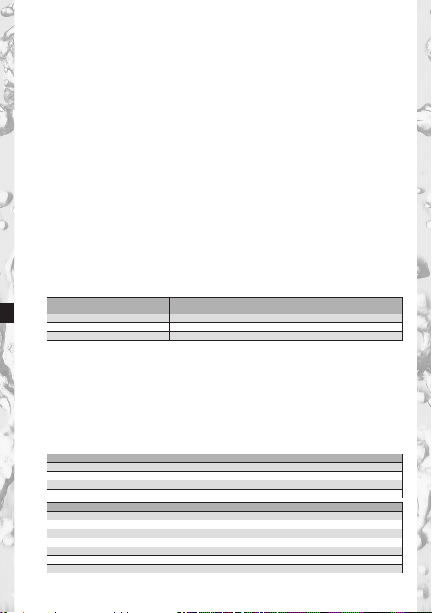
Filter System x* Flushing amount
after 2-3 days stagnation
x** Flushing amount
after 4 weeks stagnation
PURITY 450 6 litres (1.6 US gallons) 30 litres (8.0 US gallons)
PURITY 600 12 litres (3.2 US gallons) 60 litres (15.9 US gallons)
PURITY 1200 24 litres (6.4 US gallons) 120 litres (31.7 US gallons)
• The lter system is not resistant to heavily concentrated cleaning agents (e.g. bleach,
chlorinated solvents, strong oxidising agents) and must not come into contact with them.
• The lter system must not be opened or dismantled during operation.
The lter cartridge must not be opened.
• The pressure vessel and the pressure vessel lid of the lter systems have a service life of up to
ten years (from the date of installation), provided that they are installed and used correctly and the
operating conditions outlined in the Technical Data chapter are adhered to. They must always be
replaced after a maximum of ten years. The hoses must be replaced in rotation after a maximum of
ve years.
Production date:
Production code sticker lter cartridge and packaging. Example B715002010
7 Production year, here: 2017
15 Production week, here: calendar week 15
002 Batch No. lter medium, here in terms of quantity the second batch used
010 Serial number of the lter cartridge, here the tenth cartridge from the second batch
Production code sticker connector head - Example: 1001801 E 119317008764
1001801 VIVREAU identication number
ESupplier ID
7 Production year, here: 2017
19 Production week, here: calendar week 19
3Production day from Monday (1) to Friday (5), here: Wednesday
17 Production year, here: 2017
008764 Serial identication number

5
EN
Production date pressure vessel and pressure vessel lid. Example: 1117
11 Production month, here: November
17 Production year, here: 2017
3.5 Safety Assembly Instructions
• The terminal device operated with the lter must be free of limescale prior to installation.
!Caution: No water softening system may be operated upstream from the lter system.
• Protect the lter system from sunlight and mechanical damage. Do not assemble near sources
of heat and open ames.
• A stop valve must be installed before the lter system intake hose.
• If the water pressure is higher than 6.9 bar (100 psi), a pressure reducer must be installed
before the lter system.
• A non-return valve according to DIN EN 13959 tested by the DVGW has been factory installed
at the water intake of the lter head.
• No copper pipes, galvanised or nickel-plated pipes/connectors may be installed between the
water lter and the consumer. The use of VIVREAU PURITY hose sets is recommended here.
When choosing the material for parts that come into contact with water after the VIVREAU
PURITY lter system i.e. hoses it must be remembered that, due to the process, decarbonised
water contains free carbon dioxide.
• All parts must be installed in accordance with the country-specic guidelines on the installation
of drinking water facilities.
4 Installation
!
Caution: Prior to installation, read the technical data (Chapter 12) and the operating and safety infor-
mation (Chapter 3). After storage at below 0°C (32°F) the product must be stored at the ambient tempera-
ture of the installation location in its original packaging (opened) for a least 24 hours prior to commissioning.
4.1 Scope of Delivery
To install an VIVREAU PURITY Quell ST new lter you need packaging units pressure vessel (1)
(incl. lter cartridge) and pressure vessel lid (3).
Prior to installation, remove entire package contents and check that everything is present:
1 x Pressure Vessel 1
1 x Pressure Vessel Lid 3
1 x Filter Cartridge 2
1 x Manual
1 x temporary hardness test
If parts of the package contents are missing, please contact your local VIVREAU LLC Service
Address.
4.2 Assembling Pressure Vessel and Pressure Vessel Lid
• Stand with both feet on the foot rests 12 .
• Lift pressure vessel 1 and turn it clockwise until the mantle handles 16 are
over the foot rests 12 .
• Remove the transport protective cap 18 from the lter cartridge.
• Check O-ring washer of the lter cartridge 2 for correct seat in the groove
and also check for dirt and damage.
Note: The cartridge seat has been greased in the factory with
a foodsafe lubricant.
• Stand on the foot rests 12
• Put pressure vessel lid 3 in “INSERT” position on pressure vessel 1with
lock 15 in relevant groove.
• Press pressure vessel lid 3 down and turn clockwise until the lock engages.
• Put bleed hose 21 on bleed valve 9 .

6
EN
4.3 Assembling the Inlet and Outlet Hoses (e.g. Coffee Machine)
Note: The inlet and outlet hoses are not included in the standard delivery scope. The use of
VIVREAU PURITY hose sets is recommended (Chapter 13). The bleed valve 9 supplied ensures
that the hose to the consumer (e.g. coffee machine) is closed in the bleed position.
Note: No additional use of at seals.
• Fit hoses with washers at the inlet and outlet of the pressure vessel.
Pay attention to the correct seat of the O-rings at the inlet and outlet.
!Caution: The max. tightening torque at the 1" and 3/8" connections must not exceed 15 Nm!
Only connections with at seals may be used. Conical seals damage the lter head connections and
invalidate any guarantee claims! The low direction marked by arrows on pressure vessel lid 3 must
be observed. During assembly, note the installation dimensions (Chapter 12), bending radii of the
hoses and dimensions of the accessories (e.g. hose sets). The system can be operated vertically
and horizontally. If no original hoses are used, reducing adapter 17 1"–3/4" supplied must be used in
order to ensure correct sealing of the non-return valve (pre-tted in the water inlet).
5 Commissioning a New Filter
5.1 Bypass Setting for Filter Systems without and with Measuring and Display Unit
• Determining the local carbonate hardness with the enclosed temporary hardness test.
Check bypass setting at the bypass setting screw 19 .
Note: The bypass has been set to 30% at the factory and can be adjusted to the local
carbonate hardness and the application (Chapter 7).
5.2 Commissioning the Filter Systems with Measuring and Display Unit
Representation in operating mode
Local Carbonate
Hardness Set
Type/
By-Pass Proportion
Date Field: Installation or
last lter change date
Available residual
capacity in litres
Bar Display
Flow Symbol
Carbonate Hardness
The units of carbonate hardness can be set as required to German °dH (= display setting °KH),
English (°e = Clark) (= display setting °EH), French (°f) (= display setting °FH), American (grains
per gallon) (= display setting gpg) or international hardness values (mg/l CaCO3) (= display setting
mg/L). If the setting for the type of hardness (= unit) is changed while the lter is operating,
the values that were set originally are converted automatically.
Bar chart
Representation of the remaining capacity using bar charts. After installation of a new lter system or
after a lter change, the symbolized lter cartridge is completely lled with 10 bars.
Bypass proportion in percentage
The bypass proportion is dened as the proportion of decarbonized water in the total amount
of ltrate and is indicated as a percentage.

7
EN
Flow symbol
When water is removed via the lter system, a graphic wave is shown on the display.
Available remaining capacity of the lter cartridge
The remaining capacity of the lter cartridge is shown in liters or in US gallons, depending
on which has been selected.
When water is removed, it counts backwards in 1 liter or 1 US gallon stages. If the cartridge
is already exhausted, the capacity is indicated as being negative by ashing.
With a remaining capacity of 20 % the last two bars in the bar chart start to ash.
With a remaining capacity of 10 % the last bar in the bar chart ashes with the two change arrows.
From a remaining capacity of 0 % the negative bars and the change arrows ash alternately
with the remaining capacity shown in negative.
Date Field: Installation or
last lter change date
Local Carbonate
Hardness Set
Type/
By-Pass Proportion
Bar Display
Available residual
capacity in litres
Change arrow
If the monthly limit has been reached up to a month before expiry of the set time limit, it is signalled
by the date eld ashing.
If the monthly limit is 100 % reached, it is signalled by alternate ashing of the date eld and the
change arrows. If the remaining capacity and the monthly limit are exceeded, the negative remaining
capacity and the date eld ash alternately with the change arrows.
Date of the lter commissioning or last lter cartridge change
The date of lter commissioning or last lter cartridge change is indicated as follows:
American units of measurement
Example: 10.28.08
International units of measurement
Example: 28.10.08
10 Month, here October 28 Day, here the 28th day
28 Day, here the 28th day 10 Month, here October
08 Year, here 2008 08 Year, here 2008
Selecting the units of measurement
You can choose between European, American and international units of measurement on the dis-
play. For European units of measurement: depending on the type of lter system (STD, STM, or FIN),
select the specied unit of measurement for water hardness °KH, °EH, °FH, or ° DH. The unit of volume
and date format are then automatically displayed in liters and DD/MM/YY respectively.
For American units of measurement, select gpg (unit of measurement for water hardness); the unit of
volume and the date format are then automatically displayed in US gallons and MM/DD/YY respectively.
For international units of measurement, select mg/L (unit of measurement for water hardness); the unit of
volume and the date format are then automatically displayed in liters and DD/MM/YY respectively.
Parameterisation
The following parameters have to be entered:
Number of gpg (grains per gallon) or rather mg/L (CaCO3 mg/l).
• Filter system type and size
STD 4 = PURITY 450 Quell ST
STD 6 = PURITY 600 Quell ST
STD 12 = PURITY 1200 Quell ST

8
EN
STM 4 = PURITY 450 Steam
STM 6 = PURITY 600 Steam
STM 12 = PURITY 1200 Steam
FIN 6 = PURITY Finest 600
FIN 12 = PURITY Finest 1200
• Water hardness unit and water hardness value
The following units of hardness may be selected for the various types of lter system:
Unit of carbonate hardness for lter system types STD and STM:
°KH (German unit of hardness)
°EH (English unit of hardness)
°FH (French unit of hardness)
gpg (American unit of hardness)
mg/L (international unit of hardness)
Unit of total hardness for lter system type FIN may be
°DH (German unit of hardness)
°EH (English unit of hardness)
°FH (French unit of hardness)
gpg (American unit of hardness)
mg/L (international unit of hardness)
• Monthly limit 2–12
Carbonate Hardness Type/Filter System Size
Date eldExhaustion after months
• Reminder function lter usage period in months
Irrespective of the remaining capacity display function, you can set a monthly limit of 2–12
months to activate a reminder function for lter replacement. If the monthly limit has been
reached up to a month before the export of the set time limit, it is signalled by the date eld
ashing. Factory set to 12 months.
Example: When set to 9 months, the date eld starts to ash on the display after 8 months.
Operating the display unit
To operate the display unit, it must be removed from the connecting ttings.
Slide the display housing up approx. 10 mm (0.39") and pull off the display unit.
The display unit is operated using a button on the back of the display unit. The
display unit is supplied in standby mode. To activate the display, press the button
on the back once briey and then reset after inputting the parameters.
Parameter input water hardness and lter system size
At this level, parameters needed for operation are set manually.
The type and size of lter system is selected, the unit of hardness is set, the local carbonate hardness or
total hardness of the tap water is entered, and the maximum cartridge service life (monthly limit) is
activated. After this the parameters must be accepted.

9
EN
• To activate the display, press the back button once
(< 1 second) until the data eld appears.
< 1 sec FIN
• Press and hold the button (> 4 seconds and
< 10 seconds) until the parameter input for the lter sys-
tem type and size ashes. > 4 sec
• Press and hold the button (> 2 seconds) until the lter
system type (STD, STM, FIN) and corresponding value
for the lter system size (04, 06, 12) has been reached. > 2 sec
• Press the button once (< 1 second) to access the next
parameter input unit of hardness. The unit of hardness
ashes. < 1 sec
• Press and hold the button (> 2 seconds) until the
desired unit of hardness has been selected.
> 2 sec
• Press the button once (< 1 second) to access the next
parameter input hardness value. The hardness value
input ashes. < 1 sec
• Press and hold the button (> 2 seconds) until the value
for the water hardness rises and keep it pressed until
the desired value has been reached. > 2 sec
• Press the button (< 1 second) to access the next
parameter input monthly limit. The monthly limit input
ashes. < 1 sec
• Press the button (> 2 seconds) and keep it pressed
until the desired value has been reached.
> 2 sec

10
EN
The set parameters can now be accepted.
If you want to accept the parameters, proceed as follows:
• Press the button once (< 1 second) until the message
“Reset” appears and ashes.
< 1 sec
• Press the button once (> 2 seconds) until the total
capacity (at 0% bypass) and the current date appear.
> 2 sec
The set parameters have been accepted.
Note: If no input is made within 30 seconds, the display will return to standby or operating mode
without accepting amended parameters.
• Insert the display unit from the front at a height of approx. 10 mm (0.39") and slide down. The
loops on the display part must be inserted in the grooves on the measuring head. Continue with
Chapter 5.4 Flushing/Draining for Filter Systems with and without Measuring and Display Unit.
5.3 Bypass Setting
Determining the Bypass Setting
The bypass setting is identied according to the application and the carbonate hardness identied
on the basis of the bypass and capacity table (Chapter 7). Then the bypass should be set on the
bypass setting screw 19 as follows:
• Turn bypass setting screw 19 until the desired bypass (0 % – 50 %) matches the marking.
!Caution: Use Allen key 6 mm or 7/32".
!Caution: Never overwind the by-pass screw to avoid any damage.
5.4 Flushing/Bleeding for Filter Systems with and without Measuring and Display Unit
Note: A 2.7 US gallon (10 litre) bucket is needed for ushing/bleeding.
• Lay lter system down in a horizontal position.
• Open bleed valve 9.
• Open intake valve 7 on inlet hose 6 whilst holding bleed hose 21 rmly
in the bucket. Flush quantity of at least 2.6 US gallons (10 litres) with
a minimum volumetric ow of 0.8 US gallons/min (3 l/min = 180 l/h).
• Close bleed valve 9, put down lter and empty bucket.

11
EN
• Place lter in a vertical position. Carefully open bleed valve 9 while holding
bleed hose rmly in the bucket. Flush quantity of at least 2.7 US gallon
(10 litres) once again.
• Close bleed valve 9.
• Check system for any leaks.
• Note the installation date of the lter system and the next exchange date on the enclosed sticker
and attach it to the pressure vessel.
Note: There is space for several stickers on the pressure vessel. Apply the new sticker with
the installation date in the top position.
Note: Filter systems without measuring and display unit (MDU) are now ready for operation.
5.5 Checking initialisation of lter systems with a measuring and display unit
• Bypass setting in percent, remaining capacity in US gallons or rather liters, capacity bars
and the current date must be shown in the display.
Note: If these values are not shown in the display, the lter system must be ushed again
(Chapter 5.4) until the values are shown in the display. Filter systems with a measuring and
display unit are now ready for operation. Cf. Chapters 10.6 to 10.8
6 Exchanging the Filter Cartridge
!Caution: During the exchange, carefully examine all dismantled parts! Faulty parts must be
exchanged and dirty parts should be cleaned. Read the Operating and Safety Information (Chapter 3)
prior to replacement. After the product has been stored and transported at temperatures below
0°C, it must be stored with the original packaging open for at least 24 hours before commissioning
at the ambient temperatures stated in Chapter 12.
Filter systems without a measuring and display unit
The lter cartridge must be replaced after 6–12 months, at the latest 12 months after commissioning,
irrespective of the level of exhaustion of the lter system. If the capacity of the lter cartridge has
already been exhausted (Chapter 7), it must be exchanged earlier.
Filter systems with a measuring and display unit
The lter cartridge must be replaced no later than 12 months after commissioning, irrespective of
the level of exhaustion of the lter system. If the capacity of the lter cartridge has already been
exhausted (Chapter 7), it must be replaced earlier.
If the cartridge is already exhausted, the capacity is indicated as being negative by ashing.
No bars are shown in the display.
If the monthly limit for the cartridge has been exceeded, this is indicated by the date ashing.

12
EN
Resetting the display unit
To operate the display unit it has to be removed from the connecting ttings. Slide the
display housing up approx. 0.4 inches (10 mm) and pull off the display unit to the front.
The display unit is operated using a button on the back of the display unit.
• If this button is pressed (> 10 seconds), the data set on initial
installation will be accepted again, and the capacity, bypass
setting and input date are all updated.
Note: This automatically sets the monthly limit to 12 months.
Note: If no input is made within 30 seconds, the display will return to standby or operating mode
without accepting amended parameters.
Insert display unit from front at a height of approx. 0.4 inches (10 mm) and slide down.
The loops on the display part must be inserted in the grooves on the measuring head.
6.1 Removing the Filter Cartridge
• Switch off the power supply of the terminal equipment (remove plug).
• Close the inlet valve 7 on the inlet hose 6.
• Remove pressure from the system by opening ush valve 9.
Note: Insert the free end of the ush hose in a bucket. If the escaping water is more than
0.13 US gallons (0.5 litres), the inlet valve is not completely closed or is blocked with scale.
• Close ush valve 9
• Stand on the kick loops 12
• Open the pressure vessel lid by pressing the lock 15 and turning
it anticlockwise as far as it will go.
• Place the pressure vessel lid 3 vertically on both lid handles 20 .
• Note: Do not turn the lid horizontally on its head.
• Stand on the kick loops 12 with both feet while turning the pressure vessel 1 counter-clockwise
by the mantle handles 16 as far as it will go.
• Take your feet off the kick loops 12 and press the pressure vessel 1 down with both hands
on the mantle handles 16 .
• Remove exhausted lter cartridge 2 from the pressure vessel 1.
• Place the exhausted lter cartridge 2 in the sink with the connection facing down to drain
the remaining water (> 5 min.).
• Lock the exhausted lter cartridge 2 with the transport protective cap 18 of the new lter
cartridge and return in the original packaging to the appropriate VIVREAU address listed on the
back of the cover.

13
EN
6.2 Inserting the Filter Cartridge
• Check that the O-ring seal of the lter cartridge 2 is correctly seated
in the groove and also check for dirt and damage.
Note: The cartridge seat has been lubricated with food-safe lubricant
at the factory.
• Check the connector seat of the lter cartridge O-ring 2 in the pressure
vessel lid 1 for dirt and damage.
• Place the new lter cartridge 2 in the pressure vessel 1.
• Stand on the kick loops 12 with both feet, lift the pressure vessel 1.
turning it clockwise until the mantle handle 16 is over the kick loops 12 .
• Must line up with the “INSERT” groove.
• Stand on the kick loops 9 with both feet and place the pressure vessel lid
3 on the pressure vessel 1. The positioning of the arrow marking on the lid
handle 20 Press the pressure vessel lid 3 down and turn clockwise until the
lock 15 engages.
• Press the pressure vessel lid 3 down and turn clockwise until the lock
15 engages.
• Switch on power supply to the terminal device (plug).
• To ush and bleed the new lter cartridge 2, carry out the steps described under 5.3.
7 Filter Capacity
By-Pass and Capacity Table Coffee/Espresso Machines and Vending Machines
The capacities shown in the following table are based on German carbonate hardness
and are not NSF certied.
German
carbonate
hardness
°dH
Grains per
US gallon
By-pass
setting
PURITY 450 Quell ST PURITY 600 Quell ST PURITY 1200 Quell ST
Filter
capacity
in litres
Filter
capacity
in US
gallons
Filter
capacity in
litres
Filter
capacity
in US
gallons
Filter
capacity in
litres
Filter
capacity
in US
gallons
4 4 50% 8250 2179 14100 3725 25800 6816
5 5 50% 8250 2179 14100 3725 25800 6816
6 6 50% 8250 2179 14100 3725 25800 6816
7 7 50% 7071 1868 12086 3192 22114 5841
8 8 50% 6188 1634 10575 2793 19350 5111
9 9 50% 5500 1453 9400 2483 17200 4543
10 10 40% 4217 1114 7207 1904 13187 3484
11 11 40% 3833 1012 6552 1731 11988 3166
12 12 30% 3077 813 5260 1390 9624 2542
13 13 30% 2841 751 4855 1283 8884 2347
14 14 30% 2638 697 4508 1191 8249 2179
15 15 30% 2462 650 4208 1112 7699 2034
16 16 30% 2308 610 3945 1042 7218 1907
17 17 30% 2172 574 3713 981 6793 1795
18 18 30% 2052 542 3506 926 6416 1695
19 19 20% 1944 514 3322 878 6078 1606
20 20 20% 1650 436 2820 745 5160 1363
21 21 20% 1571 415 2686 710 4914 1298
22 22 20% 1500 396 2564 677 4691 1239
23 23 20% 1435 379 2452 648 4487 1185
24 24 20% 1375 363 2350 621 4300 1136
25 25 20% 1320 349 2256 596 4128 1091
28 28 20% 1179 311 2014 532 3686 974
31 31 20% 1065 281 1651 436 3329 879

14
EN
German
carbonate
hardness
°dH
Grains per
US gallon
By-pass
setting
PURITY 450 Quell ST PURITY 600 Quell ST PURITY 1200 Quell ST
Filter
capacity
in litres
Filter
capacity
in US
gallons
Filter
capacity in
litres
Filter
capacity
in US
gallons
Filter
capacity in
litres
Filter
capacity
in US
gallons
35 35 20% 943 249 1611 426 2949 779
By-pass and Capacity Table Combi ovens and conventional ovens
Select by-pass setting 10% in order to achieve an optimally treated water for the combi oven/oven.
The capacities shown in the following table are based on German carbonate hardness and are not
NSF certied.
German
carbonate
hardness
°dH
Grains per
US gallon
By-pass
setting
PURITY 450 Quell ST PURITY 600 Quell ST PURITY 1200 Quell ST
Filter
capacity in
litres
Filter
capacity in
US gallons
Filter ca-
pacity in
litres
Filter
capacity in
US gallons
Filter
capacity in
litres
Filter
capacity in
US gallons
4 4 10% 4991 1318 8530 2253 15607 4123
5 5 10% 4991 1318 8530 2253 15607 4123
6 6 10% 4991 1318 8530 2253 15607 4123
7 7 10% 4278 1130 7311 1931 13378 3534
8 8 10% 3743 989 6397 1690 11706 3092
9 9 10% 3327 879 5686 1502 10405 2749
10 10 10% 2994 791 5118 1352 9364 2474
11 11 10% 2722 719 4653 1229 8513 2249
12 12 10% 2495 659 4265 1127 7804 2062
13 13 10% 2303 608 3937 1040 7203 1903
14 14 10% 2139 565 3656 966 6689 1767
15 15 10% 1996 527 3412 901 6243 1649
16 16 10% 1872 495 3199 845 5853 1546
17 17 10% 1761 465 3010 795 5508 1455
18 18 10% 1664 440 2843 751 5202 1374
19 19 10% 1576 416 2694 712 4929 1302
20 20 10% 1497 395 2559 676 4682 1237
21 21 10% 1426 377 2437 644 4459 1178
22 22 10% 1361 360 2326 614 4257 1125
23 23 10% 1302 344 2225 588 4071 1075
24 24 10% 1248 330 2132 563 3902 1031
25 25 10% 1198 316 2047 541 3746 990
28 28 10% 1069 282 1828 483 3344 883
31 31 10% 966 255 1651 436 3021 798
35 35 10% 856 226 1462 386 2676 707
Note: The capacity limits refer to average usage of the terminal equipment. They do not include any
lter ushing or cleaning cycle allowance and depend on local water quality, ow, mains pressure
and ow continuity
Chlorine reduction
The VIVREAU PURITY water lter system has been tested according to NSF/ANSI 42 for reduction of
Chlorine. The concentration of Chlorine in water entering the system was reduced to a concentration
less than or equal to the permissible limit for water leaving the system, as specied in NSF/ANSI 42.
While testing was performed under standard laboratory conditions, actual performance of the system
may vary.
Substance Inuent challenge
concentration
Reduction
Requirement
Actual average
reduction
Chlorine 2.0 mg/l = -10% >=50% 97.1%

15
EN
Capacity and Flow rate Table based on Chlorine reduction
Water lter system PURITY 450 Quell ST PURITY 600 Quell ST PURITY 1200 Quell ST
Capacity 6,000 litres
(1,585 US gallons)
7,500 litres
(1,981 US gallons)
13,500 litres
(3,566 US gallons)
Rated service ow (lpm) 1.8 1.8 1.8
8 Repair
Regularly check the lter system for leaks. Regularly check the hoses for kinks.
Bent hoses must be replaced.
The complete lter system must be replaced in rotation after a maximum of ten years.
The hoses must be replaced in rotation after a maximum of ve years.
!Caution: Prior to changing, read the Technical Data (Chapter 12) and the Operating and Safety
Information (Chapter 3).
Regularly clean the outside of the lter system with a soft, damp cloth.
!Caution: Do not use any substances incompatible with the material (Chapter 3.4) or astringent,
abrasive cleaning agents.
9 Query Mode
The following data can be queried in the query mode:
Production data
• Briey press button once (< 1 second); the following message appears.
Serial Appliance Number Battery Service Life
ID Level Production Year
Production year: Example 08 = 2008
Device number: consecutive
Useful battery life: Example 07.10.19 = The battery in the display unit will be exhausted on 07/10/19
and the complete lter system has reached its max. usage period.
Total volume meter
• Briey press button twice (< 1 second); the following message appears.
00 level current data (today)
00 Indicator for current level Filter system size
Current dateTotal volume meter

16
EN
The total volume meter is managed at this level; it counts up from 0 irrespective
of the cartridge change.
Memory Call-Up
In the Memory Call-Up mode, the data of the last 4 lter cartridges used can be called up.
Briey press button once (< 1 second) until the following message appears:
-1, -2, -3, -4 level – data of the cartridges used before the current one.
Carbonate hardness By-pass
Total meter reading when
changing the lter cartridge
Date of inserting the cartridge
alternating
Cartridge indicator Type
At the top left, the indicator for the lter cartridge (-1 for previous lter cartridge) is displayed
alternately with the water hardness set and the hardness unit. At the top right, the lter system
size is displayed alternately with the bypass setting (display 1 s indicator, 1 s water hardness),
at the bottom left, the meter reading when changing the cartridge (-1) and at the bottom right,
the installation date of the cartridge.
Meaning: the lter cartridge most recently used was a PURITY 1200 cartridge, the lter cartridge
was inserted on 06/25/09 and operated up to a meter reading of 6619 US gallons. The water
hardness set was 14°gpg and the bypass measured was 30 %.
The same applies to the cartridge (-2), preceding lter cartridge and the other preceding lter
cartridges -3,-4.
Error Messages
Error level E1 indicates whether an error has occurred in blend detection.
E1 is activated as soon as the current bypass is not correctly identied.
The word Start is then displayed together with the date of occurrence.
alternating
As soon as the current bypass setting is identied correctly again, the error has ended and the Stop
date is added. At error level 01 the Stop and Start display alternates every second.
Error level E2 indicates whether and from when until when an error has occurred at the outlet water
meter. Display is similar to level E1.

17
EN
Program Overview
ID-Information
ÚÚÚ
00 Current level
ÚÚÚ
-1 History level 1
ÚÚÚ
-2 History level 2
ÚÚÚ
-3 History level 3
ÚÚÚ
-4 History level 4
ÚÚÚ
E1 Error inlet metre
ÚÚÚ
E2 Error drainage metre
Filter system type and size 2 sec.
ÚÚÚ
Type of hardness (unit)
and value 2 sec.
ÚÚÚ
Monthly limit 2 sec.
ÚÚÚ
RESET 2 sec.
ÚÚÚ
Parameter acceptance
Operating mode
ParameterisationRetrieval mode
1 x button Press button 4 seconds
30 sec. no activity =
no Parameter acceptance
20 sec. no activity
Carbonate hardness •
Capacity • By-pass • last
lter change date
10 Troubleshooting
10.1 No water ow
Cause: Water intake closed.
Troubleshooting: Open water intake on the upstream stop valve or inlet valve 7 on inlet hose 6.
!Caution: The following faults may be remedied only by trained and authorised personnel.
10.2 No or low water ow in spite of open water intake
Cause: Mains pressure too low.
Troubleshooting: Check mains pressure.
If the fault continues in spite of adequate mains pressure, check the lter system
and lter cartridge and change if necessary.
!Caution: Prior to changing, read the Technical Data (Chapter 12) and
the Operating and Safety Information (Chapter 3).
10.3 Leak at Screwed Connections
Cause: Screwed connections not tted correctly.
Troubleshooting: Check mains pressure. Check all screwed connections and
mount according to Chapter 4.
If the fault continues, exchange lter system.
!Caution: Prior to changing, read the Technical Data (Chapter 12)
and the Operating and Safety Information (Chapter 3).

18
EN
10.4 Leak after Filter Replacement
Cause: O-ring at the lter cartridge is not seated correctly.
Troubleshooting: Check correct seat of the O-ring (Chapter 6.2).
!Caution: Prior to dismantling read the data (Chapter 12) and the Operating
and Safety Information (Chapter 3).
10.5 No Display Function
Cause: Battery drained.
Troubleshooting: Replace display unit (Order number see Chapter 13).
Note: When replacing the display unit, follow the enclosed manual.
10.6 Data on Display Flashing
Cause: Monthly limit expired or the remaining capacity of the lter cartridge
is exhausted (Chapter 5.2).
Troubleshooting: Replace lter cartridge (Chapter 6).
10.7 Bypass setting in the display does not agree with the setting
of the bypass screw (cf. 10.8/10.9)
Cause: Filter was not commissioned correctly.
Troubleshooting: Flush lter again (Chapter 5.4). Check data in the display after ushing
(Chapter 5.5).
10.8 Bypass setting in the display does not agree with the setting
of the bypass screw (cf. 10.7/10.8)
Cause: Valve strip of the by-pass setting not set correctly.
Troubleshooting: Flush lter system again and readjust bypass screw (Chapter 5.3)
11 Battery
The installed battery is designed for a service life of approx. 10 years.
The battery and display unit must not be burnt and must not be disposed of in domestic waste;
please hand in the battery and the appliance to the collecting points designed for this purpose in
line with the local regulations.
To remove the battery, please proceed as follows:
• Remove the screw on the back of the display unit and open and remove the back of the housing.
• Disconnect the soldered contacts on the battery with side cutters and remove the battery from
the bracket.
• Replace back of the housing on the display unit and tighten screw.
• Dispose of the battery and display unit following
the local environmental guidelines for battery disposal .
12 Technical Data
Filter system VIVREAU PURITY with lter cartridge
PURITY 450 Quell ST PURITY 600 Quell ST PURITY 1200 Quell ST
MDU* distributor
head
MDU* distributor
head
MDU* distributor
head
Operating pressure 2 bar – max. 6,9 bar (29 psi – max. 100 psi)
Operating/water temperature 4°C – 30°C (39°F – 86°F)
Ambient
temperature
during
operation 10°C – 40°C (50°F – 104°F)
storage/transport –20°C – 50°C (–4°F – 122°F)
Flow rate with 1 bar (14.5 psi)
pressure loss
300 l/h (79.2
US gallons/h)
350 l/h (92.4
US gallons/h)
300 l/h (79.2
US gallons/h)
350 l/h (92.4
US gallons/h)
300 l/h (79.2
US gallons/h)
350 l/h (92.4
US gallons/h)
Nominal ow according to Norm 60 l/h (15.85
US gallons/h)
60 l/h (15.85
US gallons/h)
120 l/h (31.7
US gallons/h
120 l/h (31.7
US gallons/h
120 l/h (31.7
US gallons/h
120 l/h (31.7
US gallons/h)

19
EN
Filter system VIVREAU PURITY with lter cartridge
PURITY 450 Quell ST PURITY 600 Quell ST PURITY 1200 Quell ST
MDU* distributor
head
MDU* distributor
head
MDU* distributor
head
Pressure loss at nominal ow 0,12 bar
(1.74 psi)
0,08 bar
(1.16 psi)
0,36 bar
(5.22 psi)
0,27 bar
(3.92 psi)
0,32 bar
(4.64 psi)
0,24 bar
(3.48 psi)
Empty lter cartridge volume 3,9 l (1.03 gallon) 5,8 l (1.5 gallon) 10,9 l (2.8 gallon)
Weight (dry/wet) 10 kg/12 kg (22 lb/26 lb) 12 kg/15 kg (26 lb/33 lb) 18 kg/24 kg (40 lb/53 lb)
Dimensions complete system
(Width/Depth/Height)
249 mm (9.80 inch)
222 mm (8.74 inch)
408 mm (16.06 inch)
249 mm (9.80 inch)
222 mm (8.74 inch)
520 mm (20.47 inch)
288 mm (11.34 inch)
255 mm (10.04 inch)
550 mm (21.65 inch)
If VIVREAU hose sets are used, their bending radii of approx. 130 mm (5.12 inch) must be added.
Operating position The lter system can be operated either vertically or horizontally.
Inlet connection G 1"
Outlet connection G 3/4"
* with ACS Technology
System Tested and Certied by NSF International against NSF/ANSI Standard 42
for the reduction of Chlorine taste and odor and against CSA B483.1.
The VIVREAU PURITY Water Filter System is used to remove carbonate hardness (temporary hard-
ness/alkalinity)* from drinking water to prevent limescale deposits in downstream appliances. Do not
use with water that is microbiologically unsafe or of unknown quality without adequate disinfection
before or after the system. Use cold water only. All of the materials used are safe for use with food.
Observe relevant regulations. Read the manual prior to use.
* Not performance tested or certied by NSF.
13 Order Numbers
23
4
1
VIVREAU PURITY 450 Quell ST Article Number Item
Pressure vessel with lter cartridge 276800 1 + 2
Pressure vessel lid with measuring and display unit 1001520 3
Pressure vessel lid without measuring and display unit 276300 4
Filter cartridge 276100 2
VIVREAU PURITY 600 Quell ST Article Number Item
Pressure vessel with lter cartridge 276700 1 + 2
Pressure vessel lid with measuring and display unit 1001520 3
Pressure vessel lid without measuring and display unit 276300 4
Filter cartridge 276000 2
VIVREAU PURITY 1200 Quell ST Article Number Item
Pressure vessel with lter cartridge 276600 1 + 2
Pressure vessel lid with measuring and display unit 1001518 3
Pressure vessel lid without measuring and display unit 276200 4
Filter cartridge 275900 2

20
FR
1 Liste des pièces
1Réservoir sous pression
2 Cartoucheltrante
3 Couvercleduréservoirsouspression
4 Raccord(avecdispositifdemesurefacultatif)
5 Dispositifd’afchage(facultatif)
6 Flexibled’entrée
7 Vanned’admissionduexibled’arrivée(chapitre11)
8 Branchementdel’appareil
9 Robinetpurgeuravecdébitd’eau
10 Branchementduexibledesortie
11 Autocollantdechangementdeltre
12 Repose-pieds
13 Sailliedupied
14 Écrandudispositifd’afchage(facultatif)
15 Verrou
16 Poignéesàmanchon
17 Douilleintermédiairede1"–3/4"po
18 Capuchon
19 Visderéglagededérivation
20 Poignéeducouvercle
21 Flexiblepurgeur
2 Informationsgénérales
2.1 Fonction et application
Lesystèmedeltrationd’eauVIVREAUPURITYestutilisépourenleverlesparticulesalcalines(dureté
etalcalinitétemporaires)*del’eaupotableandeprévenirlesdépôtsdecalcairedanslesappareils
installésaprèslesystèmedeltration.Partechniqued’écoulement,l’échangeurioniqueélimine
del’eaupotableltréelesionsdemagnésium*etdemétauxlourds*,commeleplombetlecuivre.De
plus,lamasseltranteréduitlaturbidité*etlesimpuretésorganiques*,ainsiquelaquantitédesubs-
tancesaltérantl’odeuretlegoûtdel’eau(parexemple,lesrésidusdechlore)dansleltratet
l’eaudedérivation.Lesréglagesdedérivationduraccordserventàajusterladuretédel’eauselonla
duretédel’eaulocaleoulesexigencesdestypesd’utilisationoud’appareiland’obtenirunequalité
d’eaumaximale.Lessystèmesdeltrationsontoffertsentroistaillesdifférentes(PURITY450,
PURITY600etPURITY1200),chacuneenversionavecousansdispositifélectroniqueintégréde
mesureetd’afchage(AdvancedControlSystem,ACSTechnology).
LessystèmesdeltrationdotésdeACSTechnologyafchentlacapacitérestanteactuelleetle
réglagededérivationdevotrecartouche,letypeetlatailledevotresystèmedeltrationetladate
dudernierremplacementdelacartouche.C’estcequigarantituncontrôledultreetdelaltration
del’eau.Onpeuttrouverplusd’informationssurACSTechnologyauchapitre5.2.
L’IntelliBypass,uniqueensongenre,maintientladérivationdel’eauconstantependanttoute
laduréed’utilisation,indépendammentdelaconsommationdel’appareil.Onobtientainsi
constammentuneeaudequalitésupérieure,ajustéeauxexigencesdesonutilisationetaux
conditionsdel’eaulocale.
LessystèmesdeltrationVIVREAUPURITYs’utilisentengénéralavecdesmachinesàcaféet
àespresso,desdistributricesdeboissonschaudesoufroides,desfoursàvapeuretdeshumidica-
teurs.Lesystèmedeltrationestconçupouruneinstallationoùl’espaceestrestreint,particulièrement
danslesdistributricesdeboissonsetlescuisines;ilpeutêtreinstalléhorizontalementouverticalement.
Laqualitéalimentairedesproduitsdeltrationd’eauVIVREAUaétévériéeetconrmée
paruninstitutindépendant.
* NontestésparlaNSF.
This manual suits for next models
12
Table of contents
Languages:
Other Vivreau Water Filtration System manuals