T H E W O R L D P O W E R I N A N C H O R I N G S Y S T E M S
www.muir.com.au 4
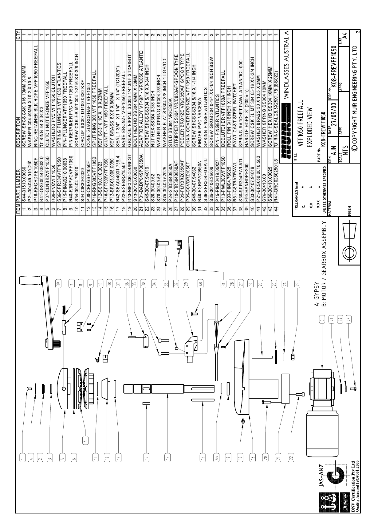
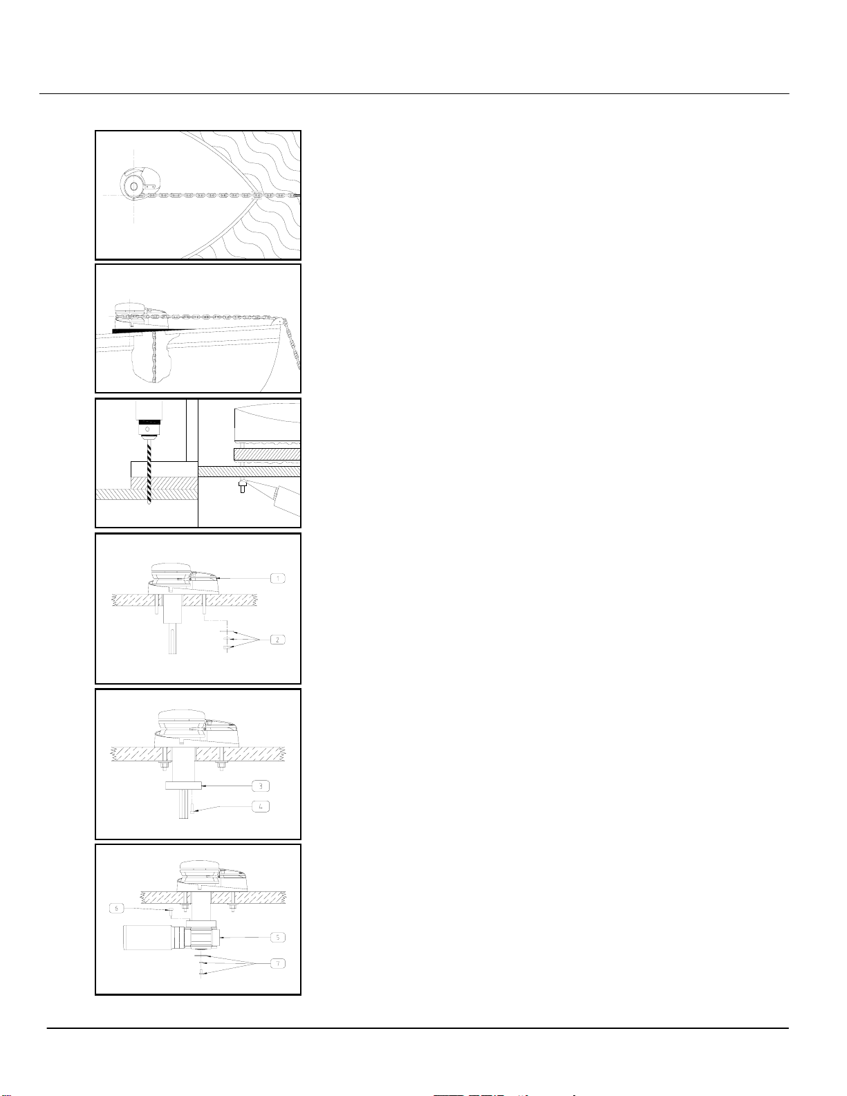
INSTALLATION
Figure(i) Locate the windlass centrally fore and aft. Check that the
chain leads unhindered to the anchor roller. The chain leads onto the
starboard side of the gypsy for a CCW, and portside of the gypsy for a
CW (see templates page 12 & 13), wraps around 180° and falls below
deck through the chain pipe (hawser). Ensure there is sufficient room
around the windlass to allow full rotation of the windlass manual/clutch
handle (if supplied).
Figure (ii) The centre height of the gypsy must be in the same plane as
the chain lead from the bow roller. If the deck is angled (fore & aft) or
curved (port to starboard) a suitably shaped mounting block will be
required to spread the load evenly over the deck surface and mount
the windlass base on a level and even footing.
Figure (iii) Place the shaped mounting block (if required) onto the
deck. Using the layout template supplied, mark the mounting centres
and drill the holes, (Refer template). When cutting out the chainpipe
hole care needs to be taken to match the template accrately, if
material is left in the hole rope jams may occur.
Figure (iv) Apply a marine grade sealant to the base plate and
mounting block (if required) and carefully tighten the nuts & washers
onto the threaded studs under the deck. Remove excess sealer.
For Aluminium or Steel hull vessels, it is important to insulate the windlass
with a non-conductive gasket to avoid corrosion. This also applies
below deck with the mounting bolts, nuts and washers.
Where the deck construction is light or of foam sandwich construction,
a plywood stiffener of at least 16mm (5/8") should be fitted to the
underside of the deck to spread the load and to prevent the bolts from
pulling through the deck. Large diameter washers on the underside of
the stiffener will assist to spread the load.
Figure (v)
1. Mount the windlass from above as shown.
2. From below, place washers and nuts on each stud and tighten each
nut progressivly in a rotation.
Figure (vi)
3. Locate adaptor and align holes.
4. Fasten using cap screws provided with loctite.
Figure (vii)
5. Grease shaft and key, slide geardrive onto shaft ensuring key is
aligned. Rotate gearbox to prefered mounting position and secure with
bolts provided.
6. Locate gearbox and bolt through adaptor.
7. Place washers and bolt in the end of the shaft and tighten / Fit
circlip.
fig i
fig ii
fig iii
fig v
fig vi
fig vii
fig iv