Muir HFF 600S User manual

T H E W O R L D P O W E R I N A N C H O R I N G S Y S T E M S
HFF600S MANUAL WWW.MUIR.COM.AU Page: 1
HFF 600S
HORIZONTAL WINDLASS
WINDLASS SERIAL NUMBER:

T H E W O R L D P O W E R I N A N C H O R I N G S Y S T E M S
HFF600S MANUAL WWW.MUIR.COM.AU Page: 2

T H E W O R L D P O W E R I N A N C H O R I N G S Y S T E M S
HFF600S MANUAL WWW.MUIR.COM.AU Page: 3
Contents
INTRODUCTION...............................................................................................................................4
IMPORTANT INFORMATION............................................................................................................4
SAFE OPERATION.............................................................................................................................4
INSTALLATION .................................................................................................................................5
DEPTH OF THE CHAIN LOCKER .......................................................................................................6
Vertical Windlass Model....................................................................................................................6
Horizontal Windlass Model ................................................................................................................6
Minimum Fall ..................................................................................................................................6
HANDY HINTS..................................................................................................................................7
ELECTRICAL .....................................................................................................................................7
Circuit breaker (must be fitted to ensure warranty)..................................................................7
Deck Switches.................................................................................................................................7
Isolating Switch................................................................................................................................7
Batteries............................................................................................................................................7
Rotation:...........................................................................................................................................7
OPERATING INSTRUCTIONS............................................................................................................9
Maintenance & servicing............................................................................................................10
Line Care......................................................................................... Error! Bookmark not defined.
Rope/Chain Splice .......................................................................................................................12
Trouble Shooting ..........................................................................................................................12
ELECTRICAL....................................................................................................................................12
MECHANICAL ................................................................................................................................12
Freefall Mechanism............................................................................................................................... 12
DRAWINGS....................................................................................................................................13
Deck Template
Wiring Diagram for 12V DC two wire 400W motor
Exploded View of HFF600S Manual Freefall
WARRANTY....................................................................................................................................15

T H E W O R L D P O W E R I N A N C H O R I N G S Y S T E M S
HFF600S MANUAL WWW.MUIR.COM.AU Page: 4
INTRODUCTION
Thank you for purchasing a Muir Windlass. Muir go to great lengths to develop anchoring systems
that not only meet all your performance and safety requirements, but at the same time designed
with a style and finish that enhances the aesthetics of your vessel. With Muir’s commitment to
quality and use of superior materials and processes we know you will be pleased with your
investment, and rest assured that through the correct installation, operation and maintenance your
new Muir Windlass will give you years of reliable performance.
IMPORTANT INFORMATION
To avoid damage to the gear drive, windlass or vessel when bringing the anchor up hard, it is a
preferred practice to mark the chain at approximately 5-meter intervals from the anchor, to alert
the operator to the anchor position. Alternatively an Auto Anchor can be used.
Under no circumstances should the windlass be operated if it is stalled or overloaded.
If anchor retrieval is impaired by high wind, heavy seas or the anchor is snagged, ease the load by
either motoring or sailing slowly forward into the wind.
SAFE OPERATION
•Ensure that hands, feet, hair and clothing are kept clear of the windlass and other loose gear
when in operation.
•Ensure no one is swimming nearby as anchor is lowered or retrieved.
•Keep hands well clear of capstan, gypsy, chain and rope.
•The windlass should never be used for lifting people aloft. Do not use a windlass as a bollard
for mooring, towing or being towed.
•When the windlass is in use or the anchor stowed, always ensure the clutch is tightened with
the clutch handle, and a Chain lock, Devils claw or Snubber Line is fitted to retain the
anchor. The use of these accessories will prevent excessive loads on the geardrive and
accidental release of the anchor.

T H E W O R L D P O W E R I N A N C H O R I N G S Y S T E M S
HFF600S MANUAL WWW.MUIR.COM.AU Page: 5
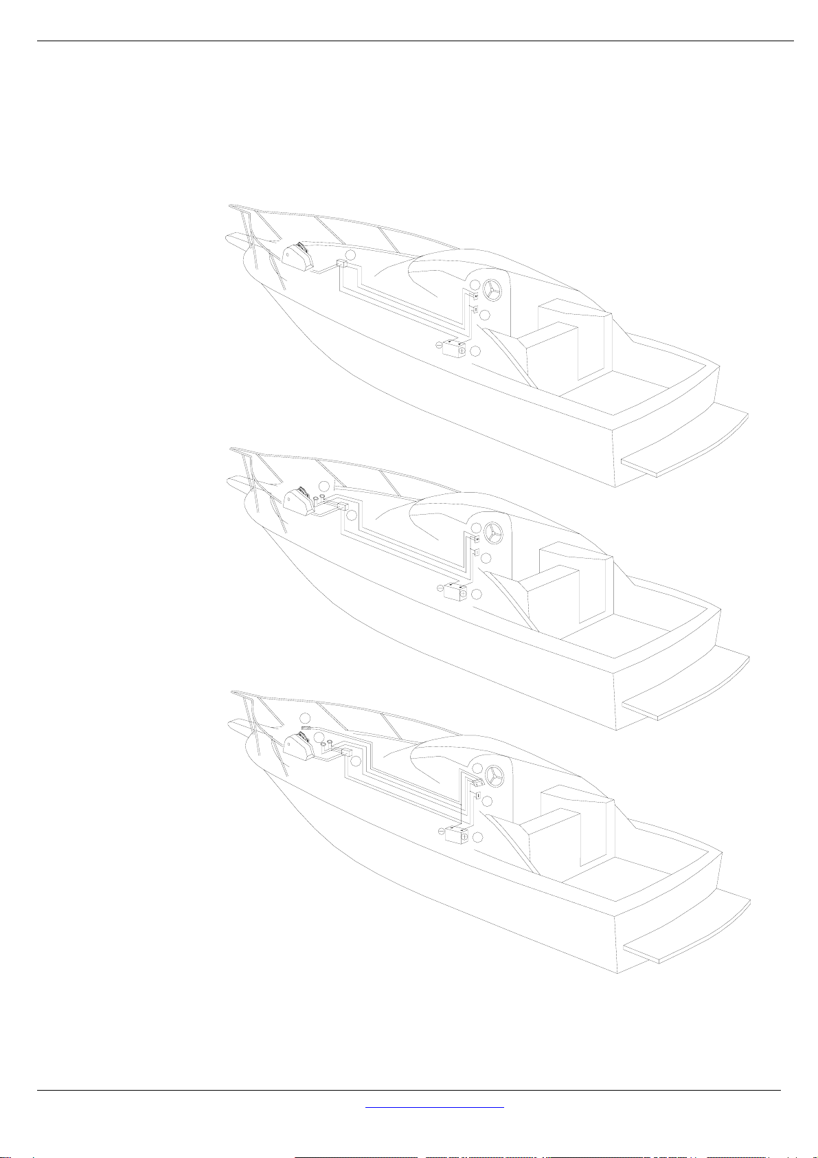
INSTALLATION
fig i
fig ii
fig iii fig iv
figvfig V
fig Vi
1
2
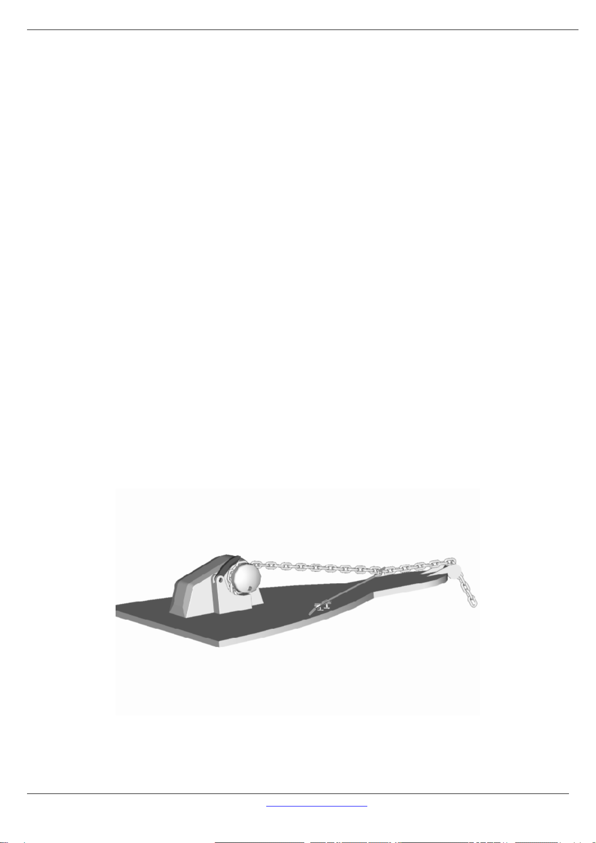
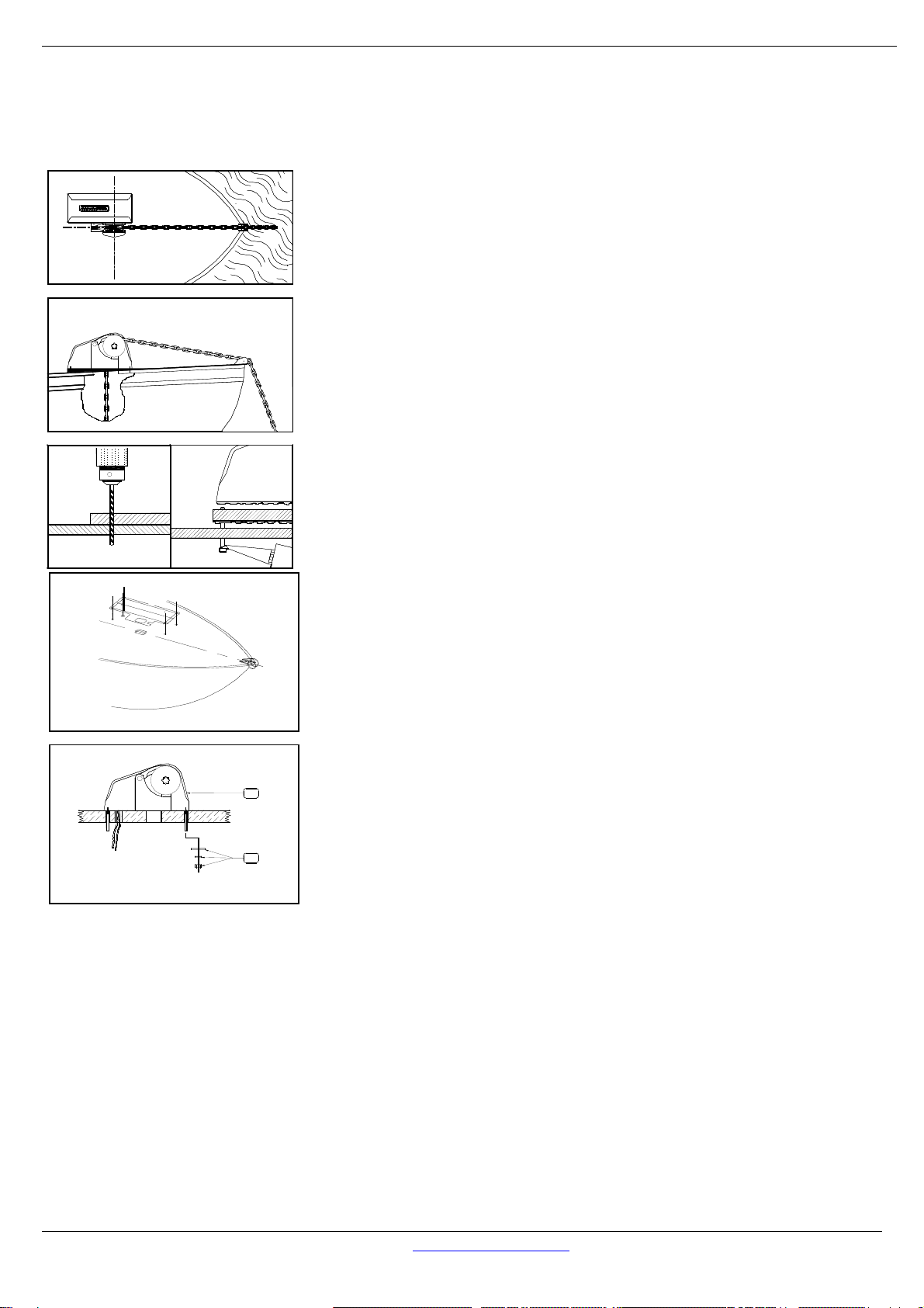
Figure(l) Locate the windlass centrally fore and aft. Check
that the chain leads unhindered to the anchor roller. The
chain leads onto the starboard side of the gypsy, wraps
around 180° and falls below deck through the chain pipe
(hawser). Ensure there is sufficient room around the windlass
to allow full rotation of the windlass manual/clutch handle (if
supplied).
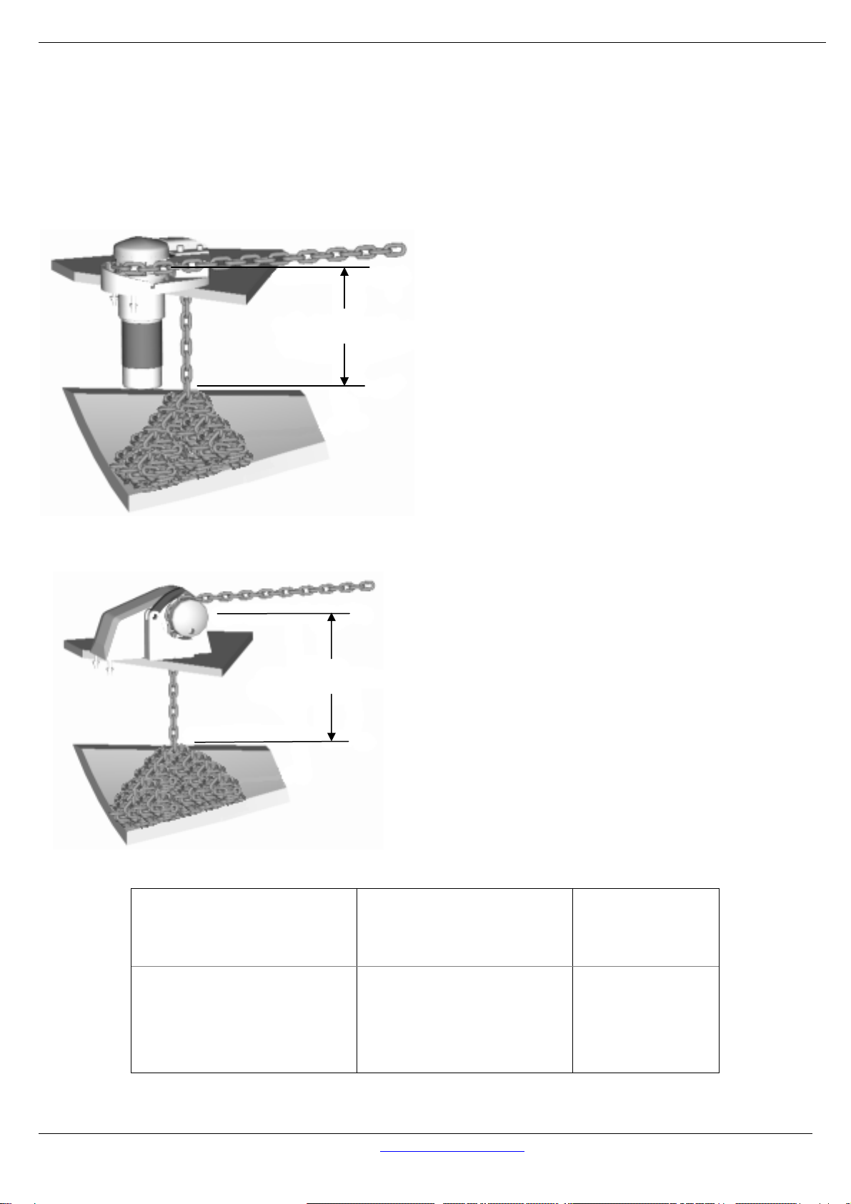
Figure (ii) The centre height of the gypsy must be in the same
plane as the chain lead from the bow roller. If the deck is
angled (fore & aft) or curved (port to starboard) a suitably
shaped mounting block will be required to spread the load
evenly over the deck surface and mount the windlass base
on a level and even footing.
Figure (iii) Place the shaped mounting block (if required)
onto the deck. Using the layout template supplied, mark the
mounting centres and drill the holes, (Refer template).
Figure (iv) Apply an appropriate sealant to the base plate
and mounting block (if required) and carefully tighten the
nuts & washers onto the threaded studs under the deck.
Remove excess sealer.
For Aluminium or Steel hull vessels, it is important to insulate
the windlass with a non-conductive gasket to avoid
corrosion. This also applies below deck with the mounting
bolts, nuts and washers.
Where the deck construction is light or of foam sandwich
construction, a plywood stiffener of at least 16mm (5/8")
should be fitted to the underside of the deck to spread the
load and to prevent the bolts from pulling through the deck.
Large diameter washers on the underside of the stiffener
assists to spread the load.
Figure (v)
1. Mount the windlass from above as shown.
2. From below, place washers and nut on each stud and
tighten.
Figure (vi)
3. Locate adaptor and align holes.
4. Fasten using cap screws provided.
Figure (vii)
5. Grease shaft and key, slide geardrive onto shaft ensuring key is aligned. Rotate gearbox to
prefered mounting position and secure with bolts provided.
6. Locate gearbox and bolt through adaptor.
7. Place washers and bolt in the end of the shaft and tighten / Fit circlip.
NOTE:
On assembly, grease all moving parts with a Lithium / Teflon based grease.

T H E W O R L D P O W E R I N A N C H O R I N G S Y S T E M S
HFF600S MANUAL WWW.MUIR.COM.AU Page: 6
DEPTH OF THE CHAIN LOCKER
Measuring the vertical distance (minimum fall) underside of the deck and the top of the completely
stored and heaped anchor rode in the locker will assist in determining the installation to suit your
vessel. Refer to the fall depth diagrams to the left, and the options detailed below. It is also
recommended that the chain be directed to the center of the chain locker.
Vertical Windlass:
The running gear, gypsy and capstan are
positioned above the deck with the motor and
gear drive below. Vertical windlasses operate at
best with greater anchor rode fall than the
horizontal windlass and a minimum fall of 300mm
from top of stacked anchor rode is
recommended. This is particularly important if
using nylon line, which does not fold and stack as
well as chain. Vertical windlasses minimise deck
intrusion and the modern curved lines of the Muir
windlass enhance the look of any vessel. A vertical
windlass provides the advantages of a I 80-degree
wrap of the anchor rode around the gypsy.
Horizontal Windlass:
Fully enclosed, above deck, this style is usually
preferred where locker space is limited or
additional fall is required. The motor and gear
drive is fully enclosed in the housing with nothing
protruding below deck. The horizontal windlass
operates with optimum anchor rode fall of at least
300mm from the top of the stacked anchor rode,
and due to the horizontal orientation of the gypsy
higher above the deck there is additional fall
provided. These units are ideally suited for vessels
with less locker space.
Vertical Windlass Model
Horizontal Windlass Model
Minimum Fall
(Dist. Top of Pile)
VR/C 600 H 600S / 700 / 806 / 808 300 mm
VR/C 850 / 1250 / 2200 HR 1200 450 mm
VR/C 2500 / 3500 HR 2500 / 3500 650 mm
VR/C 4000 HR 4000/- 4200 800 mm
MINIMUM FALL
MINIMUM FALL

T H E W O R L D P O W E R I N A N C H O R I N G S Y S T E M S
HFF600S MANUAL WWW.MUIR.COM.AU Page: 7
HANDY HINTS
It is a common mistake to locate the windlass too far forward, or too close to the bulk head, where
there is insufficient room for chain and anchor stowing. The chain fail position should be in the
centre of the chain locker. If the chain falls alongside a bulkhead or onto the stem it will pyramid
and jam.
If the chain falls into an undesirable position, a metal tube can be fitted under the hawser to
redirect the chain to a preferred position. This pipe should be at least 1 ½ times the width of the
chain. It should also have as much vertical angle as possible. Position the windlass in the best
location with the chain hawser facing forward. Ensure sufficient room to run electric cables to the
windlass. Follow the instructions on page 4 including underdeck stiffening, deck camber, alignment,
mounting blocks and sealing procedures.
ELECTRICAL
See Wiring Diagrams for wiring instructions.
Circuit breaker (must be fitted to ensure warranty)
If the windlass is overloaded or stalled the circuit breaker automatically cuts off power to the
windlass and protects the wiring and motor. The circuit breaker should not be used as an isolating
switch, purely for safety reasons.
Deck Switches are best located out to either port or starboard or directly behind the windlass in
a position where it can be easily reached with your foot or knee, preferably where you can view
the anchor and chain coming aboard.
Isolating Switch should be fitted in an accessible position for safety, ideally close to the battery
or switches. The isolating switch is not a circuit breaker.
Batteries are best located as close to the windlass as possible. Larger cables will reduce the
voltage drop to the motor and the heat generated when running the windlass. Small diameter
cables drop voltage considerably. Use the following table as a guide to your required wire size:
Distance from
battery to motor (m)
Cable Size
(mm2)
AWG
Cable
Diameter
(mm)
7 (23’) 25 3 8 (5/16”)
9 – 17 (30’ – 55’) 35 2 10 (3/8”)
Rotation: Windlasses may be wired for single or dual direction, using single or dual deck switches
for raising or lowering. Alternatively a remote control solenoid packages with Toggle Switch, Hand
Pendant or Auto Anchors are available.
Solenoid Installation
We recommend that the solenoid is installed in an
upright position, where it has minimal exposure to
seawater and in close proximity to the electric
motor of the windlass.
For wiring information, please refer to the appropriate
wiring diagram.
This wa
y
u
p

T H E W O R L D P O W E R I N A N C H O R I N G S Y S T E M S
HFF600S MANUAL WWW.MUIR.COM.AU Page: 8
4
1
2
4
BATTERY
CIRCUIT BREAKER
SOLENOID/CONTROL BOX
TOGGEL SWITCH
1.
2.
3.
4.
TOGGLE SWITCH LAYOUT
TOGGLE / DECK SWITCH LAYOUT
AUTO ANCHOR LAYOUT
3
2
5
6
4
5
2
3
1.
2.
3.
4.
5.
BATTERY
CIRCUIT BREAKER
SOLENOID/CONTROL BOX
DECK SWITCHES
TOGGLE SWITCH
BATTERY
CIRCUIT BREAKER
SOLENOID/CONTROL BOX
DECK SWITCHES
AUTO ANCHOR
AUTO ANCHOR SENSOR
1.
2.
3.
4.
5.
6.
1
1
3
NOT TO BE USED AS WIRING DIAGRAMS

T H E W O R L D P O W E R I N A N C H O R I N G S Y S T E M S
HFF600S MANUAL WWW.MUIR.COM.AU Page: 9
OPERATING INSTRUCTIONS
The concept of the Free Fall windlass is to deploy and freefall an anchor remotely from the helm
station.
1) Engaging the down switch or reversing the windlass automatically releases the clutch
released allowing the chain gypsy to free wheel thus launching the anchor.
2) Engaging the up switch of the windlass will automatically tighten the clutch allowing the
winch to take up any slack in the anchor rode. This must be done only when the anchor and
all of the rode has touched the bottom and not whilst in freefall.
3) Then release the switch when sufficient slack in the anchor rode has been taken up
4) To retrieve the anchor, operate the winch in the up direction. It is also recommended that the
vessel is motored into the wind / towards the anchor rode to minimise excessive load on the
windlass.
5) If necessary the windlass can be powered down without freefall, this can be done by
removing the Declutching Pawl. (see Maintenance and servicing step 2 Page 9).
6) The clutch can also be operated manually after the above step has been performed. The
clutch has a right hand thread, so to release the clutch insert & turn the handle (see item 30 of
exploded view K08-FREHFF0600) in a anti-clockwise direction. To tighten turn the handle in a
clockwise direction.
7) For the efficient operation of the windlass to periodically apply grease to the Declutching Pawl
(see item 25 of exploded view K08-FREHFF0600) located on top of the chain pipe.
8) The RCMS Nylon Finger (P/N. R40-FGRPVC0600A) applies pressure to the line and splice and
must be tightly tensioned onto the gypsy without line fitted by releasing the grub screw (P/N.
S35-30406.35006) and adjusting the finger pin (P/N. P15-PIN30415.88X41) by tightening Anti
Clockwise.
IMPORTANT
IT IS NECESSARY TO INSTALL AN ISOLATION SWITCH AS WELL AS A CIRCUIT BREAKER TO THE
FREEFALL WINDLASSES TO ISOLATE THE WINDLASS WHEN NOT IN USE. This is to prevent the rope
and chain from paying out if the winch is accidentally reversed

T H E W O R L D P O W E R I N A N C H O R I N G S Y S T E M S
HFF600S MANUAL WWW.MUIR.COM.AU Page: 10
Maintenance & servicing - HFF 600 Free Fall Windlass
1. You will require the following tools to complete this
procedure:
(i) Muir Clutch handle (P/N. F90-HANNYL0600)
(ii) Flat blade screwdriver
(iii) Phillips head screwdriver
(iv) 3/16” Allen key
(v) 1/8” Allen key
(vi) A Lithium/Teflon based marine grease.
(vii)HFF 600 Exploded view Dwg. K08-FREHFF
2. Removing Declutching Pawl (P/N. P13-PWL316HFF600) &
SHC Screw (P/N. S45-30406.35019). Place 3/16” Allen key
into (A) SHC Screw and turn anti-clockwise to remove.
Now the Declutch can be removed.
3a. Removing Clutch Nut (P/N. P07-CLNBRZHFF600), SHC
Screw (P/N. S45-30406.35013) & Retaining Washer (P/N.
P21-304019.2007.012). Place 3/16” Allen key into (B) SHC
Screw and turn anti-clockwise to remove.
3b. Now place the Clutch Handle (P/N. F90-HANNYL0600)
into (C) bi-square and turn anti-clockwise to remove.
Note: After Declutcher and retaining washer has been
removed the clutch can now be engaged and
disengaged manually (if required).
4. Releasing Finger (P/N. R40-FGRPVC0600A). Place 1/8”
Allen key into (D) Grub screw (P/N. S35-3040635006) and
turn anti-clockwise to release. With the tension released
from the finger it can be pivoted out of the way.
Note: upon re-assembly don’t over tension the Finger
Pin (P/N. P15PIN30415.88X41). With line removed from
the gypsy, place Screwdriver (flat blade) into slot (E)
and turn it a ¼ turn in the clockwise direction then hold.
Now place 1/8” Allen key into (D) Grub screw and turn
clockwise to tighten.
C
B
E
D
A

T H E W O R L D P O W E R I N A N C H O R I N G S Y S T E M S
HFF600S MANUAL WWW.MUIR.COM.AU Page: 11
5a. Removing Peeler (P/N. P05PLRALL0600C) & Stripper (P/N.
P19-STR3040600C). Place 3/16” Allen key into (F) SHC
Screw and turn anti-clockwise to remove.
5b. Now place Screwdriver (Phillips head) into (G)
and turn anti-clockwise to remove. Now the Peeler
& Stripper can be removed.
6. Removing Gypsy (P/N. P10-F0600BC). The Gypsy can
now be taken off the main shaft (H).
To complete the service or replacement of parts reverse the
above steps.
Note: We recommend the use of Lithium/Teflon based grease.
•Before re-assembly, grease the exposed Main
Shaft/cone (I) & Gypsy bore (J).
Line Care
Using the wrong type of line may cause the line to jam
causing excessive line wear. Muir Windlasses are designed
to run on 3-strand nylon line (supplied by Muir) which has
been specially treated with fabric softener to prevent it
from hardening. It is recommended to soak your rope in
fresh water containing fabric softener every 3 months.
In case of a rope jam, slacken off the windlass clutch to
free the jammed line. When retrieving the anchor rode do
not continue to run the windlass if the anchor or chain is
jammed, as line slippage in the gypsy will cause damage
to the line.
F
G
H
I
J

T H E W O R L D P O W E R I N A N C H O R I N G S Y S T E M S
HFF600S MANUAL WWW.MUIR.COM.AU Page: 12
Rope/Chain Splice.
1. To stop rope unravelling, seize rope 400mm(16") from
end with whipping twine. Unlay strands.
2. After placing 20mm (3/4") of heat shrink sleeve tubing
through the last link of chain, pass one strand of rope
through sleeve and chain from one side and the other two
strands of rope from the opposite side. (See illustration).
3. While pulling all three strands tight, shrink the sleeve
tightly onto the rope using a hairdryer / fan heater or by
immersing in boiling water.
4. Remove seizing and complete back splice in normal
manner for two full tucks. With a hot knife pare down the
three strands by 1/3 and insert two further tucks. Pare down by another1/3 and finish with two
tucks. Cut any remaining tails.
TROUBLE SHOOTING
Electrical
1. Check the battery circuit breaker and ensure the isolating switch is on.
2. Check battery is charged up to 12 volts.
3. Check that the foot switch plunger is contacting (if fitted)
4. Check remote control solenoid is contacting, if this is clicking the problem may be low
voltage, a faulty solenoid or a wire not properly connected.
5. Check wiring between controls, solenoid and motor are in-tact.
Mechanical
If the windlass running gear will not turn or operate check the following
1. Check that the clutch beside the chain gypsy is tightened to the chain gypsy drive
using the manual handle supplied (see operating instructions).
Freefall Mechanism
1. Check that the freefall plunger and spring can move freely.
2. Ensure that the declutcher pawl is in the correct position and that the grub screws
holding this in place are tightened.


T H E W O R L D P O W E R I N A N C H O R I N G S Y S T E M S
HFF600S MANUAL WWW.MUIR.COM.AU Page: 15
WARRANTY Limited for period of Three years (First Owner)
We warrant each new product manufactured by us to be free from defects in material and workmanship for a period of 3
years (first Owner).
This warranty shall become effective only upon receipt of a completed warranty registration, which shall identify the product
so registered by serial number. This warranty shall remain in effect for a period of three (3) years from the date of purchase.
For vessels in charter or hire the warranty is one (1) year due to various operators and overloading which may occur.
Conditions
While this warranty applies to defects in material and workmanship, it does not apply to:
• Normal worn parts or to damage caused by neglect, lack of maintenance, accident or improper service/installation or
service by persons other than an authorised Muir representative.
• Muir shall not be responsible for failures due to products being used in applications that they are not intended for, or exceed
the products performance specifications.
• For warranty claim, defective product must be returned to Muir for inspection.
• Muir will not be responsible for freight charges, removal or installation labour on warranty claims.
• Damage due to unsatisfactory storage or use of equipment prior to installation in the approved/intended manner.
Exclusions
Warranty is limited to 12 months for:
•Electric motors / controls / equipment
•Hydraulic pumps / controls /valves • Weather seals
• Use on charter/hire/commercial boats
All incidental and/or consequential damages are excluded from this warranty. Warranties of merchantability and fitness are
excluded from this warranty. Implied warranties are limited to the life of this warranty. Some countries do not allow limitations
on how long an implied warranty lasts or the exclusion or limitation of incidental or consequential damages, so the above may
not apply to you.
We reserve the right to improve the design or materials used on any product without assuming any obligation to modify any
product previously manufactured or used.
Liability
Muir Engineering liability under this warranty shall be to the exclusion of all other warranties or liabilities (to the extent permitted
by law). In particular (but without limitation):
Muir Engineering shall not be liable for:
Any indirect or consequential loss including (without limitation) any loss of anticipated profits, damage to reputation or
goodwill, loss of expected future business, damages, costs or expenses payable to any third party or any other indirect losses.
Any damage to yachts or equipment. Death or personal Injury (unless caused by Muir Engineering negligence).
- - - - - - - - - - - - - - - - - - - - - - - - - - - - - - - - - - - - - - - - - - - - - - - - - - - - - - -
WARRANTY REGISTRATION CARD
Return To
MUIR ENGINEERING PTY. LTD.
100 Browns Rd, Kingston
Tasmania, Australia, 7050
Customer / Company Name: Winch Model:
Contact (if Company): Serial Number:
Address: Purchase Date:
dd / mm / yyyy
Purchased From:
Phone / Email: Invoice Number / Receipt Number / Proof of
Purchase:

T H E W O R L D P O W E R I N A N C H O R I N G S Y S T E M S
HFF600S MANUAL WWW.MUIR.COM.AU Page: 16
Head Office:
100 Browns Road
Kingston, Tasmania, 7050
Australia
Tel Int: +61 (0) 3 6211 8811
Fax Int: +61 (0) 6229 7030
www.muir.com.au
© 2009 Muir Engineering Pty. Ltd. Muir reserves the right to alter specifications without notice. All rights
reserved.
While all due care and attention has been taken in the preparation of this manual no responsibility
shall be taken for errors or omissions.
WINDLASS ................................................................................................
SERIAL NUMBER.........................................................................................................
Table of contents
Other Muir Boating Equipment manuals
Popular Boating Equipment manuals by other brands

Quick
Quick DV5 Dave Series Manual of installation and use

Harken
Harken T3201B Online instructions

Lippert
Lippert SureShade 2000 Series installation manual

Floe
Floe V2602 LENGTH BUNKS Assembly instructions

SeaView
SeaView PMADM4M1 installation instructions

Big Air
Big Air Fusion Tower Installation and instruction manual