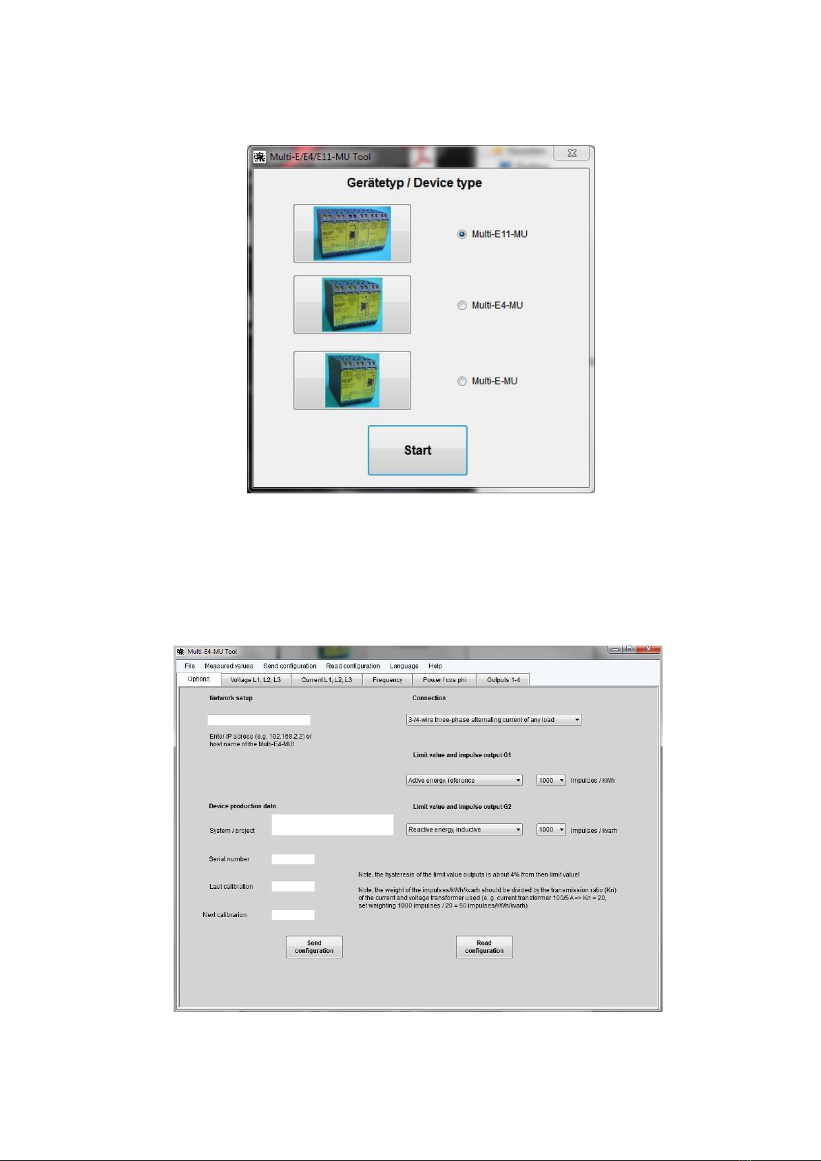
“Connection”
Here you can select the type of connection in which the transformer should take measurements.
You can select from: - alternating current
- 3-/4- wire three-phase current, asymmetric load (measuring current in all 3 phases)
- 3- wire three-phase current, asymmetric load (measuring current in 2 phases)
- 3-/4- wire three-phase current, symmetric load (measuring current in phase L1)
Important! When taking alternating current measurements, the voltage must be connected to
terminals 2 and 11 and the current to terminals 1 and 3.
“Limit value and impulses output G1”
This option allows you to set the function of the G1 output. When used as an impulse output, this output issues
active energy during the supply of energy. The number of impulses per kWh can be selected from 1 to 2000. The
impulse length is approx. 40 ms. Important! The value of the impulses per kWh must be divided by the transmission
ratio (Kn) of the current and voltage transformers used (e.g. voltage transformer 100/5 A => Kn = 20, set value 1000
impulses/20 = 50 impulses/kWh).
The G1 output can be assigned any measured value when operating as a limit value. In terms of power measured
values and power factor, it is possible to choose between energy supply and energy transfer or between inductive
and capacitive. The G1 limit output switch point is stated as a percentage of the measured value selected and its
measurement range (e.g. voltage limit value L1, measurement range
0 –250 V, switch point at 50% = 125 V). If “maximum“ is selected, the G1 limit value is activated once the limit value
has been exceeded. If “minimum” is selected, the G1 limit value is activated once the value falls below the set limit
value. Important! The limit output hysteresis amounts to approx. 4% of the set limit value.
“Limit value and impulses output G2”
The function of the G2 output can be set using this option. When used as an impulse output, this output issues
inductive reactive energy. The number of impulses per kvarh can be selected from 1 to 2000. The impulse length is
approx. 40ms. Important! The value of the impulses per kvarh must be divided by the transmission ratio (Kn) of the
current and voltage transformers used (e.g. voltage transformer 100/5 A => Kn = 20, set value 1000 impulses / 20 =
50 impulses/kvarh).
The G2 output can be assigned any measured value when operating as a limit value. In terms of performance
measured values and performance factor, it is possible to choose between energy supply and energy transfer or
between inductive and capacitive. The G2 limit value switch point is stated as a percentage of the measured value
selected and its measurement range (e.g. voltage limit value L1, measurement range 0 –250 V, switch point at 50%
= 125 V). If “maximum“ is selected, the G2 limit value is activated once the limit value has been exceeded. If
“minimum” is selected, the G2 limit value is activated once the value falls below the set limit value. Important! The
limit output hysteresis amounts to approx. 4% of the set limit value.
“Device production data”
Once the configuration data has been read from the Multi-E11/E4/E-MU, the serial number of the unit, the date of
the last manufacturer’s calibration and the date of the next manufacturer’s calibration are entered in these fields.
We recommend that the Multi-E11/E4/E-MU unit is factory inspected and recalibrated every 2 years.