multicomp pro MP710086 User manual

i
Single Output Power Supply
MP710086 & MP710087

ii
Table of Contents
1. Safety Terms and Symbols........................................................ 2
2. Panel and Interface ................................................................... 3
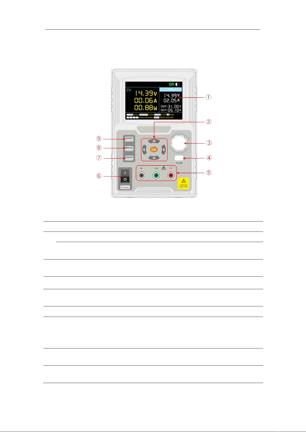
2.1.1 Front Panel ...............................................................................3
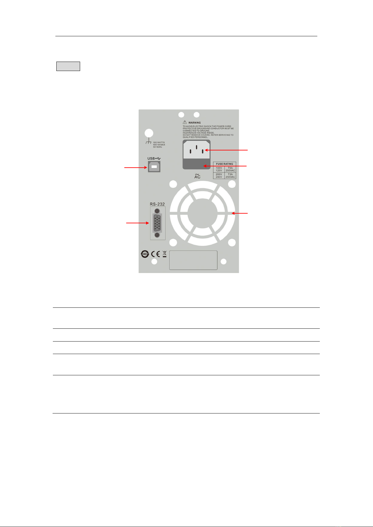
2.1.2 Rear Panel................................................................................4
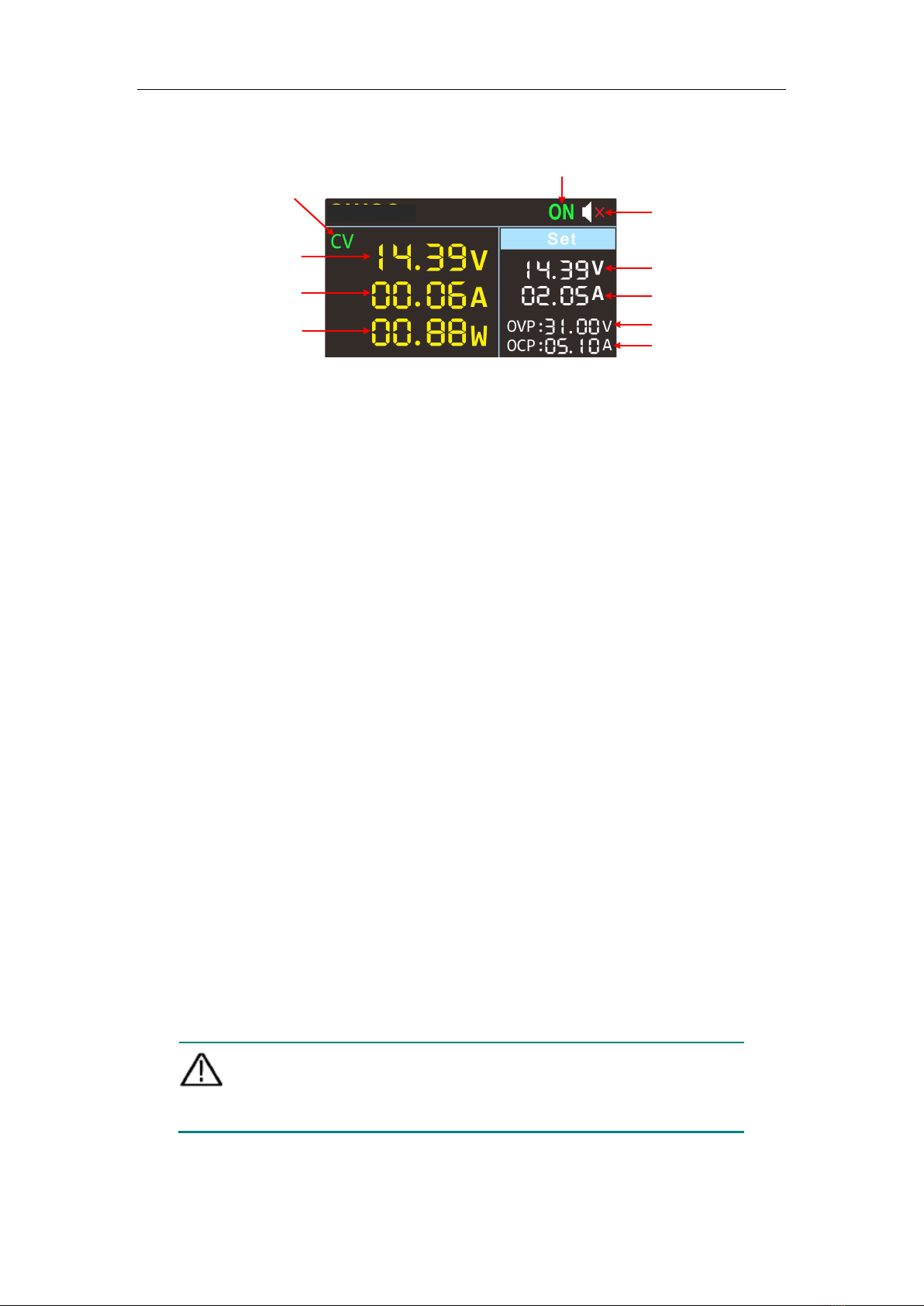
2.1.3 User Interface ...........................................................................5
2.2 General Inspection..............................................................................5
2.2.1 Check the accessories..............................................................5
2.2.2 Check the complete instrument ................................................5
2.3 Power Inspection ................................................................................5
2.4 Output Inspection................................................................................6
3. Panel Operation ........................................................................ 7
3.1.1 Turn On/Off the Channel Output...............................................7
3.1.2 Set the Output Voltage/Current.................................................7
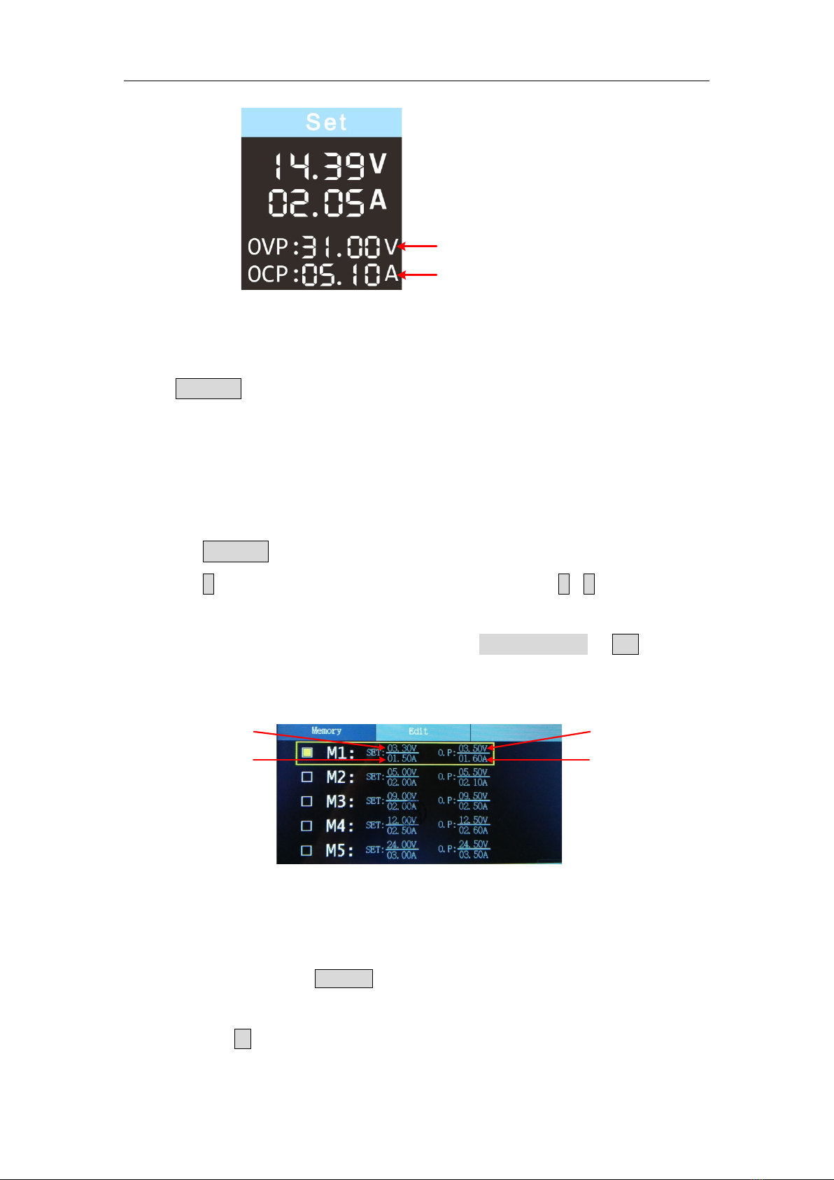
3.1.3 Over Voltage/Current Protection...............................................7
3.1.4 Memory key shortcut settings ...................................................8
3.1.5 Quick output .............................................................................8
3.1.6 Edit ...........................................................................................8
4. System Settings ........................................................................ 9
4.1.1 Display Brightness ....................................................................9
4.1.2 Language Setting .....................................................................9
4.1.3 Buzzer ......................................................................................9
4.1.4 Display (Only for MP710086 and MP710087) ..........................9
4.1.5 Curve Type You can set the type of the displayed curve to
voltage curve or current curve. ........................................................10
5. Interface Setting .......................................................................13
6. System Information ..................................................................13
6.1.1 Review System Information ....................................................13
6.1.2 Restore Factory Settings ........................................................13
7. Troubleshooting........................................................................14
8. Appendix ..................................................................................15
8.1.1 Appendix A:Accessories.......................................................15
8.1.2 Appendix B: General Care and Cleaning................................15

Safety Instructions
1
Please read these instructions carefully before use and retain for future
reference.
Check that the voltage indicated on the rating plate corresponds with
that of the local network before connecting the product to the mains
power supply.
When using electrical appliances basic safety precautions should
always be followed.
Please operate according to this manual, otherwise the protection
provided by the device will be impaired or fail.
There are no user-serviceable parts in this product. Refer servicing to
qualified personnel.
Do not operate this product with a damaged plug or cord, after a
malfunction or after being dropped or damaged in any way.
Check the product before use for any damage. Should you notice any
damage on the cable or casing, do not use.
This product must be earthed using the mains power cord ground
connection. The product must be correctly grounded before any
connection is made to the output terminals.
Children should be supervised to ensure that they do not play with the
product.
Always disconnect from the mains when the product is not in use or
before cleaning.
Do not use the product for any purpose other than that for which it is
designed.
Do not operate or store in an environment of high humidity or where
moisture may enter the product as this can reduce insulation and lead to
electric shock.
Do not cover or in any way obstruct the cooling vents or the rear fan
grille. Use in a well ventilated area.
Take great care if working on exposed circuitry to avoid risk of electric
shock or other injury.

User Manual
2
1. Safety Terms and Symbols
Terms in this manual (The following terms may appear in this manual):
Warning: Warning indicates conditions or practices that could result in
injury or loss of life.
Caution: Caution indicates the conditions or practices that could result
in damage to this product or other property.
Terms on the product. The following terms may appear on this product:
Danger: Indicates an immediate hazard or injury possibility.
Warning: Indicates a possible hazard or injury.
Caution: Indicates potential damage to the instrument or other property.
Safety Symbols
Symbols on the product. The following symbols may appear on the
product:
Hazardous Voltage
Refer to Manual
Protective Earth Terminal
Chassis Ground
Public Ground

User Manual
3
2. Panel and Interface
2.1.1 Front Panel
Figure 3-1 Front Panel Overview
①
Display Area
Display user interface.
②
Direction Key
Select menu; select parameters; Edit the cursor.
OK Key
1) Enter the menu or confirm the entered parameters.
2) Switch the display mode between Number & Curve.
③
Rotary control
Select the main menu or change the value, function
equals to the confirmation key.
④
On/Off Key
Turn on/off the channel.
⑤
Channel Output
Terminal
Output access of channel.
⑥
Power Button
Turn on/off the instrument.
⑦
Keylock Key
Long press this button for more than 5 seconds to lock
the panel button. Pressing any other button while
locked does not work. Long press this button for more
than 5 seconds to unlock.
⑧
Memory Key
5 sets of channel parameters can be stored for quick
output.
⑨
System Key
System settings, interface settings, system
information.

User Manual
4
Button light instruction
On/Off key:The key lights up when the channel is active.
2.1.2 Rear Panel
③
④
②
①
⑤
Figure 3-2 Rear Panel Overview
①
AC Power
Input Jack
AC power input interface
②
Fuse
Power fuse
③
Air Vent
Air vent
④
COM port
Connect the serial port of the instrument and external
device
⑤
USB port
It is used to transfer data when external USB
equipment connects to the power supply regarded as
"slave device". Support USBTMC communication
protocol.

User Manual
5
2.1.3 User Interface
Buzzer status
Actual voltage output
Actual current output
Actual power output
Set values of voltage
Set values of current
Set values of O.V.P
Set values of O.C.P
CV: Constant Voltage output
CC: Constant Current output
Channel output status
Figure 3-3 User Interface
2.2 General Inspection
When you have got a new power supply, it is suggested that you should
perform a general inspection on the instrument according to the following
steps.
Check whether there is any damage on it due to transportation
If the packing boxes or foam cushions are found to have serious damage, keep
them in a safe place until the complete instrument and accessories have
passed the electrical and mechanical tests.
Check the accessories
Check that all the parts and accessories are included and in serviceable
condition.
Check the complete instrument
If the instrument is damaged in its appearance or it fails in normal operation or
performance test, do not use it and contact the supplier directly.
2.3 Power Inspection
(1) Use the power cord supplied with the accessories to connect the
instrument to the AC power.
Warning:
To prevent electric shock, make sure that the instrument is
properly grounded.
(2) Press the power button on the front panel, the button light will be on, and
the startup screen will be displayed on the screen.

User Manual
6
2.4 Output Inspection
Output inspection is to ensure that the instrument can achieve its rated outputs
and properly respond to operation from the front panel. For the procedures
below, it is suggested that you read "Turn On/Off the Channel Output" on page
8 and "Set the Output Voltage/Current" on page 7.
2.4.1 Voltage Output Inspection
The following steps verify basic voltage functions without load:
(1) When the instrument is under no load, select a channel and ensure the
output current setting for this channel is not at zero.
(2) Turn on the channel output, then ensure the channel is in Constant
Voltage output mode.
(3) Set some different voltage values on this channel; check if the actual
voltage value displayed is close to the set voltage value, and also that the
actual current value displayed is nearly to zero.
(4) Check that if the output voltage can be adjusted from zero to the maximum
rating.
2.4.2 Current Output Inspection
The following steps check basic current functions with a short across the
power supply's output:
(1) Connect a short across (+) and (-) output terminals with an insulated test
lead on this channel. Use a wire size sufficient to handle the maximum
current.
(2) Set the output voltage to the maximum rating on this channel.
(3) Turn on the channel output. Ensure the channel you used is in Constant
Current output mode.
(4) Set some different current values on this channel; check if the actual
current value displayed is close to the set current value, and to check if the
actual voltage value displayed is nearly zero.
(5) Check that if the output current can be adjusted from zero to the maximum
rating.
(6) Turn off the channel output and remove the short circuit from the output
terminals.

User Manual
7
3. Panel Operation
3.1.1 Turn On/Off the Channel Output
Press the On/Off key to turn on/off the channel.
3.1.2 Set the Output Voltage/Current
In the channel setting area, press the
∧
/
∨
keys to move the red cursor
between parameters. After selecting the output voltage/current setting value,
turn the rotary control to change the current cursor value, and press
<
/
>
key to move the cursor position.
Set values of voltage
Set values of current
3.1.3 Over Voltage/Current Protection
When the Over Voltage Protection (O.V.P) or Over Current Protection (O.C.P)
is enabled, once the output voltage/current reaches the set value of
O.V.P/O.C.P, the instrument will cut off the output, a warning will show on the
screen.
Note:
When the instrument disables the output due to protection, after you
make some adjustments, the channel must be restarted to output
normally.
This function can keep the power output from exceeding the load rating to
protect the load.
In the channel setting area, press the
∧
/
∨
keys to move the red cursor
between parameters. After selecting the overvoltage/overcurrent protection
value, turn the Rotary control to change the current cursor value, and press the
<
/
>
direction key to move the cursor position.

User Manual
8
Set values of O.V.P
Set values of O.C.P
3.1.4 Memory key shortcut settings
Press Memory key on front panel, the M1, M2, and M3 keys can store five
sets of channel parameters M1, M2, M3, M4, and M5, respectively, for quick
output.
3.1.5 Quick output
To output a set of parameters from M1 to M5, follow these steps:
(1) Press Memory key on front panel, the shortcut interface will display.
(2) Press
∨
key and shows the yellow select box. Press
∧
/
∨
to move the
select box.
(3) After selecting the certain parameter, press rotary control or OK on the
panel to confirm the input value.
Set values of voltage
Set values of current
Set values of O.V.P
Set values of O.C.P
3.1.6 Edit
To edit the channel parameters of M1 to M5, follow these steps:
(1) Press the front panel Memory button, the screen displays the quick setup
interface.
(2) Press the
>
arrow keys to display the editing interface.

User Manual
9
(3) Press the
∨
keys to show a red cursor.
(4) Press the
∧
/
∨
/
<
/
>
keys to move the red cursor between
parameters. Turn the rotary control to change the current cursor value,
press the
<
/
>
arrow keys to move the cursor.
Set values of voltage
Set values of current
Set values of O.V.P
Set values of O.C.P
4. System Settings
4.1.1 Display Brightness
Press the System softkey and turn the rotary control to highlight the System
main menu. Press the
∨
keys to highlight the Brightness submenu. Press the
<
/
>
keys to adjust the brightness of the screen. The adjustment range is
from 1 to 100.
4.1.2 Language Setting
Press the System softkey and turn the rotary control to select the [Utility]
menu. Press the
∨
arrow keys to choose the language. Press the
<
/
>
arrow keys to select the desired language. Supported languages include
Chinese and English.
4.1.3 Buzzer
Press the System softkey and turn the rotary control to select the [Utility]
menu. Press the
∨
arrow keys to choose buzzer submenu. Press the
<
/
>
arrow keys to toggle the beeper on/off. When the buzzer is on, the status bar
icon lights up. When the system prompts, it beeps, such as when the
output is cut due to overvoltage/overcurrent protection.
4.1.4 Display (Only for MP710086 and MP710087)
Press the System softkey and turn the rotary control to select the [Utility]
menu. Press the
∨
arrow keys to choose Display submenu. Press the
<
/
>

User Manual
10
arrow keys or turn the rotary control to set the display mode to Number or
Curve.
In system main interface, you can also press the OK key or press the rotary
control to toggle between Number and Curve display mode.
Number
Press the System softkey and turn the rotary control to select the [Utility]
menu. Press the
∨
arrow keys to choose Display submenu. Press the
<
/
>
arrow keys or turn the rotary control to set the display mode to Number.
In system main interface, you can also press the OK key or press the rotary
control to select the Number display mode. When the power supply is
powered on, the default display mode is Number.
Curve
Press the System softkey and turn the rotary control to select the [Utility]
menu. Press the
∨
arrow keys to choose Display submenu. Press the
<
/
>
arrow keys or turn the rotary control to set the display mode to Curve.
In system main interface, you can also press the OK key or press the rotary
control to select the Curve display mode.
4.1.5 Curve Type
You can set the type of the displayed curve to voltage curve or current curve.
1) Voltage Curve
Two methods to set the curve type to voltage curve.
1st Method:

User Manual
11
Press the System softkey and turn the rotary control to select the [Utility]
menu. Press the
∨
arrow keys to choose Display submenu. Press the
<
/
>
arrow keys or turn the rotary control to set the display mode to Curve. Press
the
∨
arrow keys to choose CurveType submenu, press the
<
/
>
arrow
keys or turn the rotary control to set the curve type to Volt.
2nd Method:
In system main interface, you can also press the OK key or press the rotary
control to select the
Curve display mode. Press the
∧
/
∨
arrow keys to select the Volt curve type.
The display mode of Volt curve is as below:
Note: In Volt curve display mode, you can still set the value of voltage or
current. Press the
<
/
>
arrow keys or turn the rotary control to enter
editing mode (edit voltage first). If the value is not changed, editing mode will
be exited.
2) Current Curve
Two methods to set the curve type to current curve.
1st Method:
Press the System softkey and turn the rotary control to select the [Utility]
menu. Press the
∨
arrow keys to choose Display submenu. Press the
<
/
>
arrow keys or turn the rotary control to set the display mode to Curve. Press
the
∨
arrow keys to choose CurveType submenu, press the
<
/
>
arrow
keys or turn the rotary control to set the curve type to Curr.
2nd Method:
In system main interface, you can also press the OK key or press the rotary

User Manual
12
controlto select the
Curve display mode. Press the
∧
/
∨
arrow keys to select the Curr curve type.
The display mode of Curr curve is as below:
Note: In Curr curve display mode, you can still set the value of voltage or
current. Press the
<
/
>
arrow keys or turn the rotary control to enter
editing mode (edit current first). If the value is not changed, editing mode will
be exited.
Curve Time
Press the System softkey and turn the rotary control to select the [Utility]
menu. Press the
∨
arrow keys to choose CurveTime submenu. Press the
<
/
>
arrow keys or turn the rotary control to set the display mode to Curve.
Press the
∨
arrow keys to choose CurveTime submenu, press the
<
/
>
arrow keys or turn the rotary control to set the curve time to 30S or 60S..

User Manual
13
5. Interface Setting
(1) Press the
∨
arrow keys to select the baud rate, and press the
<
/
>
arrow keys to set the baud rate of the RS232 serial interface. The optional
values for the baud rate are: 2400, 4800, 9600, 19200, 38400, 57600,
115200, and the factory default setting is 115200. Make sure the
instrument's baud rate setting matches the baud rate setting of the
computer you are using.
(2) Press the
∨
arrow keys to select the check digit and press the
<
/
>
arrow keys to toggle None, Odd, Even.
(3) Press the
∨
arrow keys to select the stop bit, and press the
<
/
>
arrow
keys to toggle 1 or 2.
Note: The data bits submenu cannot be set, and the data bits are fixed at 8
bits.
6. System Information
6.1.1 Review System Information
Press the System softkey and turn the rotary control to select the [SYSTEM]
menu. The screen shows the model number, version number, and serial
number of the machine.
6.1.2 Restore Factory Settings
Press the System softkey and turn the rotary control to select the [SYSTEM]
menu. Press
∨
arrow keys to select the Factory Reset submenu. Press OK to
restore the factory default settings. See the factory setting detail table below
Output Voltage Current
5 V 2 A
Limit
Voltage Current
MAXOUT MAXOUT

User Manual
14
System
Backlight
50%
Buzzer
On
Port Port
Setting
Baud Rate
115200
Data Digit
8
Parity Check
None
Stop Digit
1
Display (Only for
special models)
Number
7. Troubleshooting
1. The instrument is powered on but no display showing.
Check if the power is connected properly.
Check if the fuse which is below the AC Power socket is used
appropriately and in good condition (the cover can be pried open with a
straight screwdriver).
Restart the instrument after the steps above.
2. The output is abnormal:
Check if the output voltage is set to 0V. If so, set it to other value.
Check if the output current is set to 0A. If so, set it to other value.
When in programmable output status, check if there is any
voltage/current value is set to 0. If so, set it to other value.

User Manual
15
8. Appendix
8.1.1 Appendix A
:
Accessories
standa
rd:
Power Cord
RS232 Cable
User Manual
Fuse
optional
:
Banana plug to
crocodile clip
test leads
USB2.0 to S232
common port
connector
8.1.2 Appendix B: General Care and Cleaning
General Care
Do not store or leave the instrument where the liquid crystal display could be
exposed to direct sunlight for long periods of time.
Caution: To avoid any damage to the instrument, do not exposed it to any
sprays, liquids, or solvents.
Cleaning
Inspect the instrument as often as operating conditions require. To clean the
instrument exterior, perform the following steps:
Wipe the dust from the instrument surface with a soft cloth. Take care not to
scratch the transparent LCD protection screen when cleaning.

User Manual
16
Clean the instrument with a lightly damp soft cloth. It is recommended to wipe
with mild detergent or fresh water. To avoid damage to the instrument, do not
use any corrosive chemical cleaning agent.
Warning: Before re-applying power, ensure that the instrument is
completely dry, avoiding any electric shock or electrical short circuit
resulting from moisture.
INFORMATION ON WASTE DISPOSAL FOR CONSUMERS OF
ELECTRICAL & ELECTRONIC EQUIPMENT.
When this product has reached the end of its life it must be treated as Waste Electrical &
Electronics Equipment (WEEE). Any WEEE marked products must not be mixed with
general household waste, but kept separate for the treatment, recovery and recycling of the
materials used. Contact your local authority for details of recycling schemes in your area.
Made in China
LS12 2QQ
This manual suits for next models
1
Table of contents
Other multicomp pro Power Supply manuals