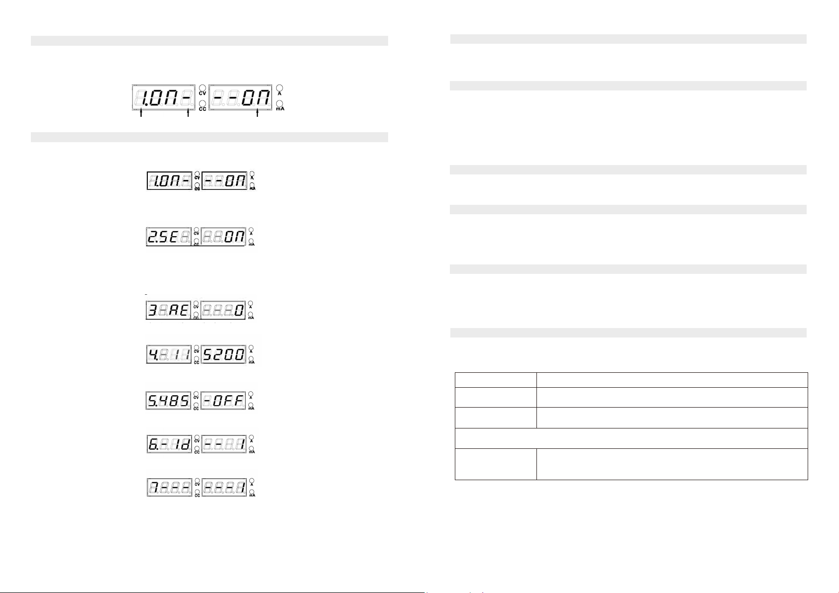
multicomp pro MP710995 User manual

INFORMATION ON WASTE DISPOSAL FOR CONSUMERS OF ELECTRICAL &
ELECTRONIC EQUIPMENT.
When this product has reached the end of its life it must be treated as Waste Electrical & Electronic
Equipment (WEEE). Any WEEE marked products must not be mixed with general household waste,
but kept separate for the treatment, recovery and recycling of the materials used. Contact your local
authority for details of recycling schemes in your area.
Made in China.
PO Box 13362 Dublin 2
LS12 2QQ
Digital Control & Programmable DC Power Supply
User Manual
MP710995, MP710996
MP711005, MP711006, MP711007
MP711008 and MP711009

12
IMPORTANT SAFETY INFORMATION
Please read these instructions carefully before use and retain for future reference.
The following safety symbols may appear
in this manual or on the series:
Do not block or obstruct the opening
to the cooling fan vent.
Avoid severe impacts or rough
handling as it could lead to damage.
Do not discharge static electricity.
Do not disassemble unless you are
qualified as service personnel.
AC INPUT
AC input voltage: 220V / 240V, 50Hz.
This device must be grounded through the mains plug to avoid electric shock.
OPERATION ENVIRONMENT STORAGE ENVIRONMENT
FUSE
Model
110V / 120V
220V / 230V
MP710996 MP711006 MP711007 T4A/ 250V (20x5mm) T2A/ 250V (20x5mm)
MP710995 MP711005 MP711008 MP711009 T5A/ 250V (20x5mm) T3A / 250V (20x5mm)
•
Avoid the risk of fire by only replacing the fuse with the specified type and rating.
Disconnect the power before replacing the fuse.
•
Make sure the cause of the fuse blowing is fixed before replacing the fuse.
Symbol
The lower computer responds
Slave
Address
Function
Code
Data length
Data CRC
L
CRC
H
Instructions
01H
01H
(N+?) / 8
-8bit
XXH
XXH
XXH
Address:0000H-
BIT0 0001H-
BIT1..
01H
05H
set an address
0001H -16bit
FF00H -16bit
XXH
XXH
Return the commands of upper
computer
01H
03H
2N -8bit
2N data
XXH
XXH
Function: return the data value to be
read Data: a data integer of 16-bit
floating-point
01H
010H
Starting and
ending
addresses
-16bit
N-number of
writing
addresses
-16bit
XXH
XXH
Function: return function code, start
address, address length
Location
Indoor, no direct sunlight, dust
free, almost non-conductive
Relative Humidity
<80%
Altitude
<2000m
Temperature 0-40°C
Location
Indoor
Relative Humidity < 70%
Temperature
-10-70°C

11
2
Correspondence Table of Models and Functions Modbus Protocol
Mode
V
meter
A
meter
Resolution
Current Read
Resolution (C>0.5A)
and (C<=0.5A)
External
interface
Analogue
control
interface
RS232
USB
MP710996
MP711005
4 digit
4
digit
10mV/1mA
1mAand0.1mA
No
No
No
MP710995
4 digit
4digit
10mV/1mA
1mAand0.1mA
External switch
and voltage
compensation
No
Yes
MP711006
4digit
4digit
10mV/1mA
1mAand0.1mA
External switch
and voltage
compensation
No
No
MP711007
4digit
4digit
10mV/1mA
1mAand0.1mA
External switch
and voltage
compensation
Yes
No
MP711008
MP711009
4digit
4digit
10mV/1mA
1mAand0.1mA
External switch
and voltage
compensation
Yes
Yes
MP710995
MP711008 MP711009
:
RS485 and MODBUS communication
functions are added on the models
based on the
according functions on the above table.
Main Features:
•
Low noise: the cooling fan is controlled by the radiator temperature.
•
High-precision voltage and current output (see parameter table), and maximum resolution 0.1mA of current reading.
•
Constant Voltage/Constant Current operation
•
Output ON/OFF control
•
Voltage, current and power display
•
Digital panel control
•
4 pairs of saving/recalling panel settings
•
Coarse and fine voltage/.current control
•
Software calibration
•
Keyboard LOCK function
•
Over-Voltage and Over-Current Protections that can set parameters
•
Reverse polarity protection
•
Short circuit protection
•
Analog control interface and external switch control interface (only for some models)
•
Output terminal voltage compensation (only for some models)
•
USB/RS232 for remote control (only for some models)
•
RS485 control interface (only for some models)
FRONT PANEL OVERVIEW
Display of voltage
Setting memory indicator
Over-current protection
Over-voltage
protection
Buttons for saving and recalling M1-M4
Remote voltage compensation button (some models)
Over-current protection button
Over-voltage
protection
Output Memory ON/OFF
Power output terminal
Current value
Power value display
Output on/off indicator
Remote voltage compensation
Rapid adjustment knob
for voltage and current
Coarse and fine voltage/
current adjustment buttons
Voltage/current selection
Cancelling voltage/current settings
Power on/off button
The connected computer sends instructions
Slave Address
Function
Code
Set an
Address
Data length/setting content
CRCL
CRCH
Instructions
01H
01H
OOOOH
N-16bit
XXH
XXH
Function: read machine status
Address: OOOH-CC/CV
0001H-ON/OFF indicates the output
0004H- beep
0005H-LOCK indicates the lock
0006H-OVP
0007H-OCP
OOOAH-SENSE external compensation
OOOCH-ON/OFF external switch
01H
05H
0001H
FFOOH
XXH
XXH
Function: set machine status
Address: 0001H-ON/OFF indicates the output
0004H-beep
0005H-indicates the lock
0006H-OVP ON/OFF
0007H-OCP ON/OFF
0008H- indicates the AUTO mode
OOOAH-SENSE external compensation
OOOCH-ON/OFF external switch
Setting content: FFOOH-turning ON
OOOOH-turning OFF
01H
03H
OOOOH
N-16bit
XXH
XXH
Function: read the voltage and current
values of the device
Address: OOOOH-0001H output voltage
0002H-0003H output current
0004H-0005H set voltage
0006H-0007H set current
0008H-0009H set OVP
OOOAH-OOOBH set OCP
01H
010H
0004H
N-16bit
(How many
addresses
to write)
The length
is 2N bytes
-8bit
XXH
XXH
Function: set voltage and current values
of the device
Address: 0004H-0005H set voltage
0006H-0007H set current
0008H-0009H set OVP

10
3
Bit Content
Description
DISPLAY
0
CH1
1
CH2
0=CC mode, 1=CV mode
=CC mode, 1=CV mode
2, 3 Tracking 01=independent, 11=serial connection, 10=parallel connection
Voltage setting value
or voltage output value
Voltage setting value
or voltage output value
Power output value
10.
*IDN?
Description: Returns the MP710995A identification.
Example
*IDN?
Contents MP7XXXX V4.0 (Manufacturer, model name,).
11.
RCL<NR1>
Description: Recalls a panel setting.
NR11-5: Memory number 1 to 5
Example RCL1
Recalls the panel setting stored in memory number1
12.
SAV<NR1>
Description: Stores the panel setting.
NR1 1-5: Memory number 1 to 5
Example SAV1
Stores the panel setting stored in memory number1
13.
OCP<Boolean>
Description: Stores the panel setting.
Boolean: 0 OFF, 1 ON
Example:
OCP1
Turns on the OCP
14.
OVP<Boolean>
Description: Turns on the OVP.
Boolean: 0 OFF, 1 ON
Example:
OVP1
Turns on the OVP
15.
POWER?
Description: Output power reading.
Example: POWER? Turns on the power
16.
CURRENTA
CURREN MA
Description: Switch the current display unit to A or mA.
Example: CURRENT A Turns on the power
17.
ANALOGE1
Description: External analog signal controls output.
Example: ANALOGUE1 Turns on External analog signal controls
output
18.
Read analog signal setting
ANALOGUE? reading data 1 means turning ON
and 0 means turning OFF.
19. External switch control
Description: Turns on external switch control.
Example: EXON: 1 Turns on external switch control
20. Connection terminal compensation setting
Description: Connection terminal compensation setting.
Example: SENSE:1 Open Connection terminal compensation
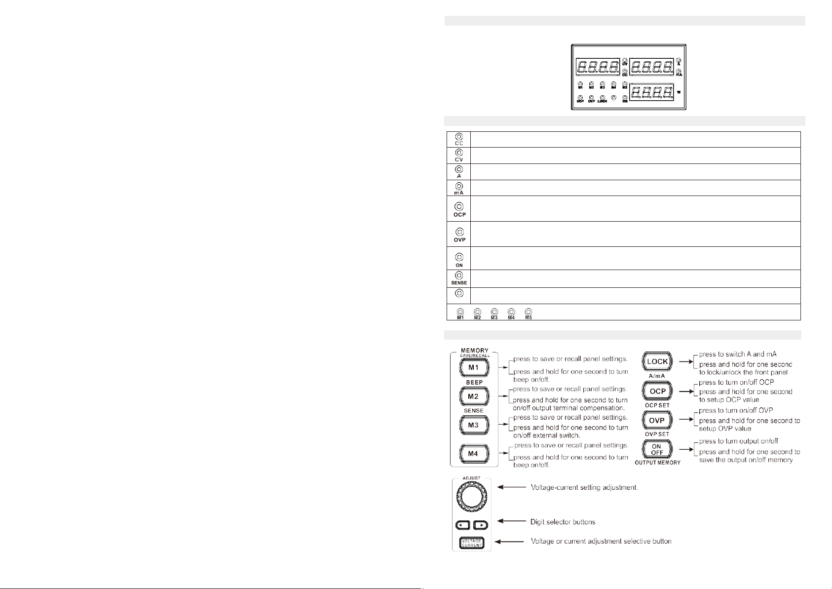
CONDITION INDICATION
when this light is ON, it means that the output of the power supply is constant current.
when this light is ON, it means the power output is constant voltage.
A, this light is always ON, indicating that the unit of the current measurement value is A.
mA, this light is always ON to indicate that the unit of the current measurement is mA.
When this light is always ON, it means that OCP is turned on, and when this light is
flashing, it means OCP parameter setting.
OVP, when this light is always ON, it means that OVP is turned on, and when this light is
blinking, it means OCP parameter setting.
This light is lit to indicate that the output is turned on, and this light is bickering to
indicate that the output shutdown memory is turned on.
SENSE, this lights up to indicate that the output voltage compensation function is enabled.
LOCK
LOCK, this light illuminates to indicate that the keyboard is locked.
M1 - M5, save/recall indicators
BRIEF INTRODUCTION OF PANEL OPERATION
4
Beep
0=OFF, 1=ON
5
OCP
0=OCP OFF, 1=OCP ON
6
Output
0=OFF, 1=ON
7
OVP
0=OVP OFF, 1=OVP ON

4
9
Rear Panel and Interfaces of Machine and Control Terminal Remote Control Syntax V4.0
MP710995
MP711005, MP711008 and MP711009
Series
Command format: VSET<X>:<NR2>
1.
VSET: Command header
2.
X: output channel
3.
separator
4.
NR2: parameter
Wiring Diagram of Analogue
Interface
(only for some models)
OPERATION
Connect the AC power cord and select the corresponding AC voltage according
to the back label, the connect the AC power cord to the socket on the back panel.
press the power switch to turn the power on. The display initializes
showing the model of the machine and the setting level which is recalled
from the last use.
Press the power switch again to turn the power off.
Output Control and Output Shutdown Memory of Power Supply
• Press Output will be turned on, the positive and negative terminals will output
according voltage and the output indicator light will be lit ON.
• Press and hold for one second, and then the output indicator will be lit ON. At this
time, the machine will memorize the output status before shutting down, and the last status
will be exactly what the power supply is set to when you power ON next time.
Note: If there are any of the following conditions, the output will automatically turn off:
•
OVP turns on and then there is unusual voltage on the input terminal which is
more than the setting voltage.
•
OCP turns on and then there is unusual current on the output terminal which is
more than the setting current.
•
Recalling other setups from the memory.
Command Details:
1.
ISET<X>:<NR2>
Description: Sets the output current.
Example:
ISET1:2.225
Sets the CH1 output current to 2.225A
2.
ISET<X>?
Description: Returns the output current setting.
Example:
ISET1?
Returns the CH
1
output current setting
3.
VSET<X>:<NR2>
Description: Sets the output voltage.
Example:
VSET1:20.50
Sets the CH1 voltage to 20.50V
4.
VSET<X>?
Description: Returns the output voltage setting.
Example:
VSET1?
Returns the CH1 voltage setting.
5.
IOUT<X>?
Description: Returns the actual output current.
Example:
IOUT1?
Returns the CH
1
output current
6.
VOUT<X>?
Description: Returns the actual output voltage.
Example:
VOUT1?
Returns the CH
1
output voltage
7.
BEEP<Boolean>
Description: Turns on or off the beep. Boolean: boolean logic.
Example:
BEEP1
Turns on the beep.
8.
OUT<Boolean>
Description: Turns on off the output.
Boolean: 0 OFF, 1 ON
Example:
OUT1
Turns on the output
9.
STATUS?
Description: Reads the status of the power supply.
Contents: 8 bits in the following formats:
Fan
Label for voltage
and fuse
Power Socket

6
7
SOUND ON/OFF
• By default, the beep sound is enabled.
• To turn off the beep, press the
BEEP
key for one second.
• A beep sounds, confirming the sound setting will be turned off.
• To enable the beep, press the
key for one second again.
BEEP
FRONT PANEL LOCK
Press the key for one second to lock the front panel key operation. The key LED will turn on.
To unlock, press and hold the LOCK key for one second.
OUTPUT SET
Panel Operation
• Connect the load to the front port.
• Voltage or current adjustment selective button, press for the first time, and then the voltage
setting value will blink. At this time, you can adjust the voltage setting value by rotating the
adjustment knob. Then press the Voltage/Current button again to make the current setting
value blink, and then to adjust the current setting value through rotating the knob. And the
setting blinking time is around 8 seconds. If you want to end the setting blinking, press and
hold the button for 0.5 second.
Size and weight
Models Dimensions Weight
MP710995, MP710996,MP711005, MP711006,
MP711007, MP711008 and MP711009
262*110*160mm 4.3kg
•
By default, the voltage and current knob work in coarse mode. In order to activate in yne mode,
press the key to choose between coarse or yne mode.
• Turning on the output and pressing the output key will turn on the key LED and display CV
or CC mode.
SAVE SETUP
Contents
The following list shows the setup contents:
•
Fine/coarse knob editing mode
•
Beep on/off
•
Output voltage/current level
•
Output on/off (The shutdown memory must be set to make it saved)
Panel Operation
Press one of the four buttons (M1, M2, M3, M4) and the LED light
turns on accordingly. After adjusting the value, it is automatically
saved, once the LED light stops blinking.
RECALL SETUP
The front panel settings can be recalled from one of the four internal memories.
Press any button M1 to M4.
For example, the memory of the panel setting is recalled in M1.
After you recall M4, rotate the shuttle knob and then M5 is recalled.
If the memory indicator is lit on the panel of lights, then the current memory is recalled.
Note: When a setting is recalled the output automatically turns off.
Line Regulation
Voltage
Current
:S0.01%+3mV
:S0.1%+3mA
:S0.01%+3mV
:S0.1%+3mA
:S0.01%+3mV
:S0.1%+3mA
:S0.01%+3mV
:S0.1%+3mA
:S0.01%+3mV
:S0.1%+3mA
:S0.01%+3mV
::S0.1%+3mA
Setup Resolution
Voltage
Current
10mV
1mA
10mV
1mA
10mV
1mA
10mV
1mA
10mV
1mA
10mV
1mA
Setup Accuracy (25°C to -5°C)
Voltage
Current
:S0.5%+20mV
:S0.5%+3mA
:S0.5%+20mV
:S0.5%+5mA
:S0.5%+30mV
:S0.5%+3mA
:S0.5%+30mV
:S0.5%+3mA
:S0.5%+20mV
:S0.5%+10mA
:S0.5%+30mV
:S0.5%+5mA
Ripple (20-20m)
Voltage
Current
:S1mVrms
:S3mVrms
:S2mVrms
:S3mVrms
:S1mVrms
:S3mVrms
:S1mVrms
:S3mVrms
:S2mVrms
:S5mVrms
:S1mVrms
:S3mVrms
Temperature Coefficient
Voltage
Current
:S150ppm
:S
150ppm
:S150ppm
:S150ppm
:S150ppm
:S150ppm
:S150ppm
:S150ppm
:S150ppm
:S150ppm
:S150ppm
:S150ppm
Read Back Accuracy
Voltage
Current
1OmV
1mA
10mV
1mA
10mV
1mA
10mV
1mA
10mV
1mA
10mV
1mA
Read Back Temperature Coefficient
Voltage
Current
:S150ppm
:S
150ppm
:S150ppm
:S150ppm
:S150ppm
:S150ppm
:S150ppm
:S150ppm
:S150ppm
:S150ppm
:S150ppm
:S150ppm
Reaction Time
Voltage Rise
Voltage
Drop
:S100mS
:S
1OOmS
(10% rated load)
:S100mS
:S1
OOmS
(10% rated load)
:S100mS
:S1
OOmS
(10% rated load)
:S100mS
:S1
OOmS
(10% rated load)
:S100mS
:S1
OOmS
(10% rated load)
:S100mS
:S1
OOmS
(10% rated load)
Analogue Programming:
0-10V control (only for some models)
External voltage control output voltage
Accuracy and linearity: ±0.1% of rated output voltage+15mv.
External voltage control output current
Accuracy and linearity: ±0.5% of rated output current+5mA.

6
7
Press and hold the button M4 (menu) for one second to enter the setting interface of function menu.
Press the left and right key to switch into different settings. To exit, press and hold the button M4 (MENU)
for one second. And the instructions of menu settings are as follows:
Function Serial No. Split symbol and function code Parameter settings
1.
External switch control - turn the knob to change the setting, and ON parameter indicates enabling
the external output switch while OFF indicates turning off the external control switch.
2.
Connection terminal compensation setting - turn the knob to change the parameter setting, and ON
parameter means turning on the output terminal compensation while OFF means turning off the output
terminal compensation.
3.
External setting of analog control setting - turn the knob to change the parameter setting, 0 refers
to turning off this function; 1 means the external analog voltage control, and current value is subject to
fixed setting; 2 refers to the external analog current control, and the voltage value is subject to fixed
setting; 3 means the voltage and current are controlled respectively by the external analog control.
4.
The communication baud rate setting - the baud rate can be set to 9600, 18400, 39600, 115200 by
adjusting the knob.
5.
485 communication mode is turned on - adjust the knob to change the 485 communication mode
(ON or OFF).
6.
485 communication address setting - turn the knob to set 485 communication address.
7.
485 communication format settings - 485 communication format can be set by adjusting the knob.
0: Low-Endian
1: High-Endian
2:Low-Endian data exchange mode
3:High-Endian data exchange mode
All models can be connected to a computer through interfaces USB/RS232 on the back of the
machine and controlled by the remote control.
Set up the COM port inside the computer according to the following list:
Baud rate: 9600,19200,38400,57600,115200
Parity bit: None
Data bit:8
•
Stop bit:1
•
Data pow control: None
•
Run this query command via the terminal application, such as MTTTY (Multi-threaded TTY).
•
This should return the identification information: Manufacturer, model name, serial number,
•
Connect the USB.
•
The power supply will automatically connect. After a normal connection, there will be an
audible indication from the power supply itself.
•
The panel keys are locked, so the power supply can only rely on the remote control.
•
Close the remote control software.
•
Disconnect the USB from the back.
•
The power supply disconnects. You will hear a beep, which hints that the remit control is over.
•
The power supply automatically comes in the panel control mode.
Note: The specifications in the table below have all been tested in temperature ranging from
25° down to -5° and after being warmed up for 20 minutes.
Model
MP710995 MP710996 MP711005 MP711006 MP711007 MP711008 MP711009
Voltage Range
0-30V
Current Range 0-5A
Load Regulation
Voltage
Current
<0.01%+2mV
<0.1%+5mA
Setting of Function Menu
REMOTE CONTROL
Function Descriptions of Serial Number:
COM setting
Functionality Check
Entering the Remote Control Mode:
Exiting from the Remote Control Mode:
SPECIFICATIONS
This manual suits for next models
6
Table of contents
Other multicomp pro Power Supply manuals