multicomp pro MP740068 User manual

1
Model: MP740068 Soldering Station
and MP740069 Dual Soldering Station

2
IMPORTANT SAFETY INFORMATION
Please read these instructions carefully before use and retain for future reference.
When using electrical appliances basic safety precautions should always be
followed.
• Check that the voltage indicated on the rating plate corresponds with that of the
local network before connecting the appliance to the mains power supply.
• This appliance can be used by children aged from 8 years and above and persons
with reduced physical, sensory or mental capabilities or lack of experience and
knowledge if they have been given supervision or instruction concerning use of the
appliance in a safe way and understand the hazards involved.
• Do not leave the soldering station unattended, while it is powered on.
• Never touch the soldering tip or the surrounding metallic parts before the soldering
tip has cooled down completely.
• Do not use the product near ammable items.
• Turn the power off when this product is not in use.
• The soldering iron must be placed on its stand when not in use.
• Before storage, turn the power off and allow the product to cool down to room
temperature.
• Do not use this product for anything else other than that for which it is designed.
• Children should be supervised to ensure that they do not play with the appliance.
• Do not use this appliance with wet hands.
• Do not expose the soldering station to rain or moisture.
• Ensure there is sufcient space and ventilation around the appliance to allow the
escape of heat and/or fumes.
• This appliance must be earthed.
WHAT’S INCLUDED?
• Control Station
• Soldering Iron(s)
• Mains Lead
• Iron Holder with tip cleaner
• 3.5mm grounding plug
• User Manual
OVERVIEW
Soldering Iron Soldering Iron
Temperature Controls
Iron Connectors
Tip Cleaner
Iron Holder
Iron Holder
Temperature Indicator
Soldering Station

3
Note: The rst time you use the soldering iron, it may smoke slightly as the heating
element dries out. This is normal and should only last for a few minutes.
ONLY USE FOR ELECTRICAL WORK - Acidic solder will damage the iron tip.
• Connect the plug on the soldering iron lead to the socket(s) on the lower front of
the station.
• Place the iron(s) in their holders.
• Connect the mains lead to the socket on the rear and connect to the mains supply
and turn on the power using the switch on the rear of the station. The LCD will
illuminate when the power is on.
• After a short initial self test display indicating system version number the LCD will
display the last set temperature for each channel.
1. Channel 1 power bar / product working status / abnormal code.
2. Channel 2 power bar / product working status / abnormal code.
3. Actual tip temperature display of channel 2.
4. Set temperature display of channel 2.
5. Soldering tool model identication of channel 2.
6. Quick access preset temperature setting 3.
7. Indicator to show temperature is locked for channel 2.
8. Temperature Centigrade/Fahrenheit setting display .
9. Quick access preset temperature setting 2.
10. Quick access preset temperature setting 1.
11. Soldering tool model identication of channel 1.
12. Set temperature display for channel 1.
13. Actual tip temperature display of channel 1.
MP740069 Model Dual Channel Display
XX-XXXX XX-XXXX

4
1. Power bar / product working status / abnormal code.
2. Quick access preset temperature setting 3.
3. Indicator to show temperature is locked.
4. Temperature Centigrade/Fahrenheit setting display .
5. Quick access preset temperature setting 2.
6. Quick access preset temperature setting 1.
7. Soldering tool model identication.
8. Set temperature display.
9. Actual tip temperature display.
MP740068 Model Single Channel Display
APPLICATION & OPERATION
1. Channel 1 connector.
2. Channel 2 connector (GT6200).
3. Down button.
4. Preset temperature 1 button.
5. Menu button.
6. Up button.
7. Preset temperature button 2.
8. Preset temperature button 3.
XX-XXXX

5
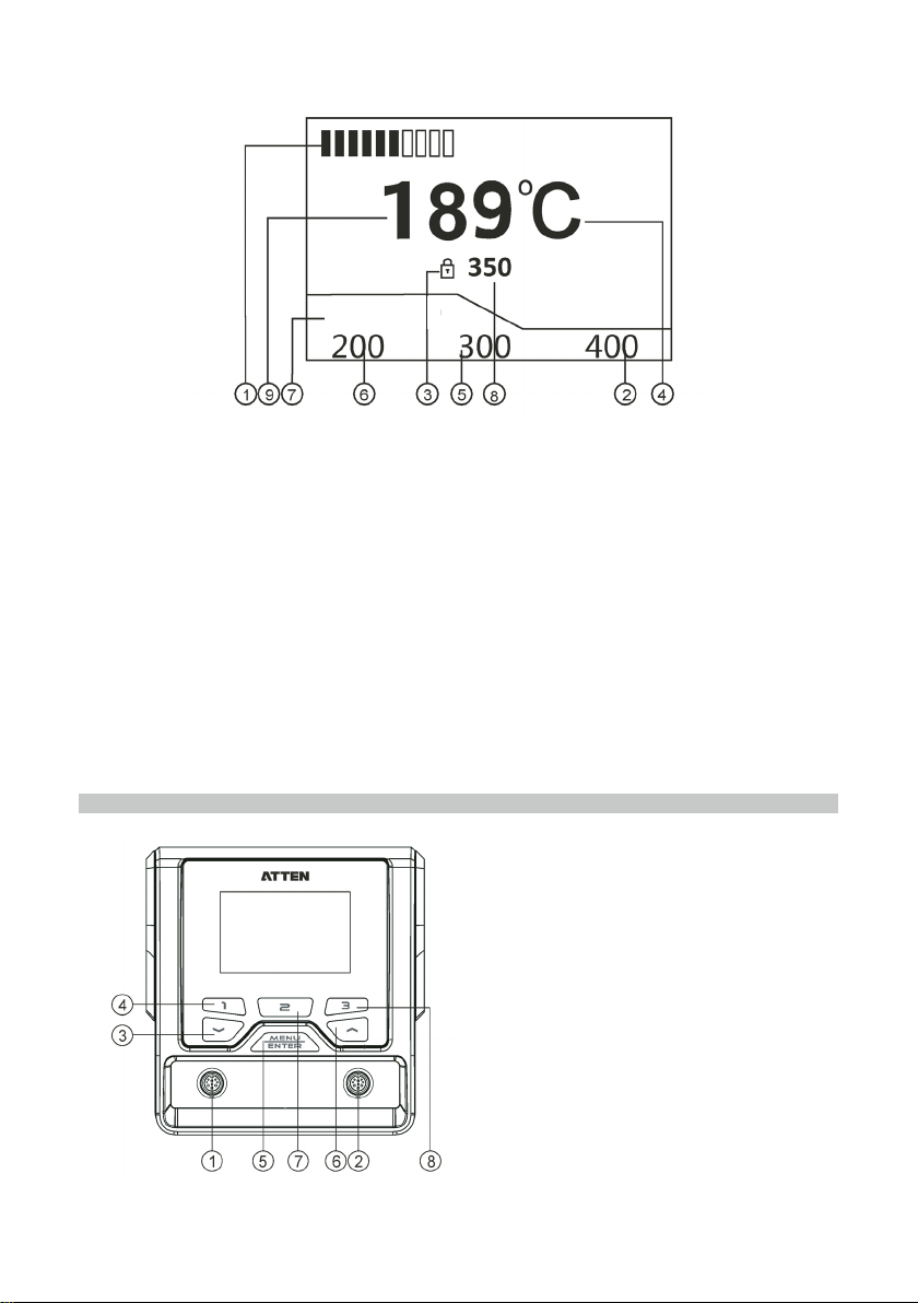
• Short press the “Menu” button to select the channel that needs to be congured
(MP740069 only). The tool identication display will indicate the chosen channel.
• Press “Up” button to increase the required temperature or press “Down” to lower it
and the display will display the setting.
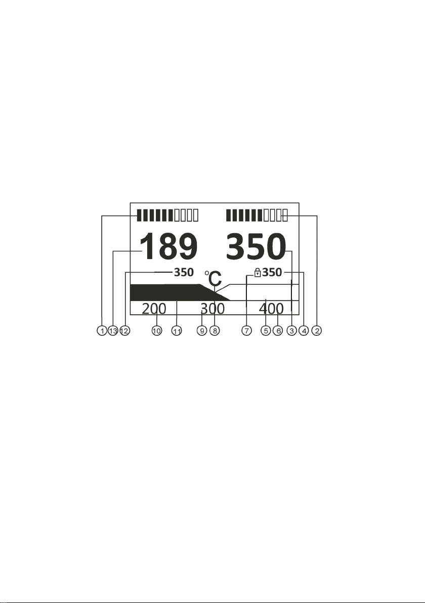
• Press “1” button to select the preset 1 temperature for the chosen channel
• Press “2” button to select preset 2 temperature.
• Press “3” button to select preset 3 temperature.
Note:
the preset temperatures of 200/300/400
o
C can be amended in the settings menu.
SYSTEM SETTING
System Parameter Setting
• Press and hold the “Menu” button until the loading function is complete.
• If a passkey has been set, enter each digit by using “Up” or “Down” buttons then
press “Enter” to move to the next digit.
• When the last correct digit is entered or if no passkey has been set, the System
Parameter menu is displayed.
• Press “Up” or “Down” buttons to change the default settings and press “Enter” to
move to the next option.
• Default unit is oC.
• If a passkey is set, the ability to change any parameters including temperature
setting option is prevented unless the passkey is entered.
• When the correct passkey is entered again in the parameter setting menu, the
passkey is cleared and operation is unlocked.
Channel Setting
• The tool you wish to use on the channel must be connected, then press button
“1” or “3” for 2 seconds to select the channel (MP740069 model) to display the
settings for.
• Do not connect or disconnect the soldering tool while in channel setting parameter
mode or damage may occur.
• Press “Up” or “Down” buttons to change each of the default settings and press
“Enter” to move to the next option.
• Factory default can be selected for each channel separately to restore all settings
to ‘as new’ condition.
1. Temp Offset: Used to compensate for any errors in the actual tip and the required
temperature of the soldering tool.
Compensation range: -50oC ~ +50oC, -90oF ~ +90oF. When the value is positive,
the tip temperature will increase according to the set value; when the value is
negative, the tip temperature will decrease according to the set value. The factory
default value is 0.
2. Standby Temp: The temperature of the iron when the system is under the standby
mode. When the iron is in standby mode, the maintained temperature is:
150°C / 302°F: the lowest standby temperature.
300°C / 572°F: the highest standby temperature allowed.
When the actual operating temperature is less than the user set standby
temperature, the product will enter the standby mode and maintain the actual
operating temperature. The factory default is: 150°C.

6
GROUNDING FUNCTION
3. Standby Delay: Turn on and off the standby timer function.
The product automatically enters into the standby state based on the set delay
value (unit: 1~120 minutes) if the iron is idle for a long time.
The factory default is OFF so the soldering iron will not enter into the standby
state.
4. Shutdown Delay: Turns on or off the safety shut down timer function.
The product automatically enters into the shutdown state based on the set delay
value (unit: 1~120 minutes) if the iron is idle for a long time.
The factory default is OFF so the soldering iron will not enter into the shutdown
state.
5. Shortcut Temp 1: Allows adjustment of the preset temperature 1.
6. Shortcut Temp 2: Allows adjustment of the preset temperature 2.
7. Shortcut Temp 3: Allows adjustment of the preset temperature 3.
A total of 3 preset temperatures are available for users to quickly call subject to the
temperature lower limit and temperature upper limit settings.
8. Fix Temp: After this mode is activated, the tip temperature is locked at this preset
value. Users cannot adjust the temperature in the main interface.
9. Temp UL: the highest temperature that the user can congure in the main working
interface.
10. Temp LL: the lowest temperature that the user can congure in the main working
interface.
The maximum congurable maximum temperature is: 480°C / 896°F.
The maximum congurable minimum temperature is: 150°C / 302°F.
The setting for the temperature upper limit must be higher than the temperature
lower limit value.
The factory default upper value is: 450°C / 842°F.
The factory default lower value is: 150°C / 302°F.
• To store all changes, select “EXIT” and press “Enter”
• This product uses 3.5mm grounding plug, which provides the following four
grounding modes:
When the equipotential bonding mode is chosen: the
ground wire can achieve the required function by being
connected to either pins 1, 2 or 3.

7
TEMPERATURE COMPENSATION
• If the actual temperature of the soldering iron tip does not match the displayed
gure when measured accurately a compensation can be set to correct this.
• Enter the system settings menu by pressing and holding the MENU key until the
load function has completed.
• Enter passkey if set or the display will go straight to the system parameter settings
menu.
• Press button “1” or “3” to select the channel you wish to adjust (MP740069 only)
and then use “UP” or “DOWN” buttons to select the Temp Offset option.
• If the actual tip temperature is lower than the displayed temperature set a positive
matching value or a negative value if the tip temperature is higher.
• Press “ENTER” to save the value for that channel.
TROUBLESHOOTING
CLEANING
• Cleaning should only be done when the iron is switched off and at room
temperature.
• The irons and station may be cleaned with a damp cloth and a small amount of
liquid detergent if necessary.
• Never submerse the soldering iron in liquid or allow any liquid to enter the case.
• Do not use any chemicals, abrasives or solvents that could damage the soldering
iron or station.
E-1 Thermal Fuse Open circuit in the heating element - check connections
or replace
E-2 Sensor Alarm Heater thermal sensor is damaged - replace heater
element
E-9 Non Compliant Tool
Connected
The iron connected is not compatible with the station

8
INFORMATION ON WASTE DISPOSAL FOR CONSUMERS OF ELECTRICAL &
ELECTRONIC EQUIPMENT.
When this product has reached the end of its life it must be treated as Waste
Electrical & Electronics Equipment (WEEE). Any WEEE marked products must
not be mixed with general household waste, but kept separate for the treatment,
recovery and recycling of the materials used. Contact your local authority for details
of recycling schemes in your area.
Made in China. LS12 2QQ
Man Rev 1.0
SPECIFICATIONS
Product MP740068 MP740069
Voltage 230V~50Hz
Power 150W 200W
Fuses T 2.5A (230V AC) T 2.5A (230V AC)
Temperature
Range 150oC~480oC / 302oF~896oF - depends on tools attached
Temperature
Accuracy ±8oC / ±15oF
Temperature
Stability ±2oC / ±4oF
Channels 12 - tools can be connected
simultaneously
Functional
Ground
Connector
3.5mm plug (which is hard grounded when not connected, is
directly connected to the protective ground wire)
Display
Resolution 240 x 160 DPI (white letters on blue)
Comms
address range 1~255 (when implemented)
Working
Environment Temperature 0oC~40oC Relative humidity <80%
Storage
Environment Temperature -20oC~80oC Relative humidity <80%
Dimensions
(mm) 315(L) × 252(W) × 127(H)
Weight 4kg Approx
This manual suits for next models
2
Table of contents
Other multicomp pro Soldering Gun manuals

multicomp pro
multicomp pro MP740841 User manual

multicomp pro
multicomp pro MP740888 User manual

multicomp pro
multicomp pro MP740893 User manual

multicomp pro
multicomp pro MP740842 User manual

multicomp pro
multicomp pro MP740999 User manual

multicomp pro
multicomp pro MP740842 User manual

multicomp pro
multicomp pro MP740073 User manual

multicomp pro
multicomp pro MP740111 User manual

multicomp pro
multicomp pro MP740029 User manual