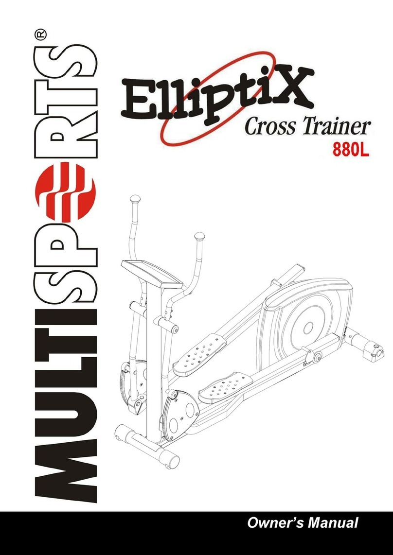
MultiSports CC-755R User manual

INDEX
IMPORTANT SAFETY NOTICE …………………………………………………………………… P. 1
ASSEMBLY TOOLS & HARDWARE LIST ………………………………………………………. P. 2
ASSEMBLY INSTRUCTIONS ……………………………………………………………………... P. 3 - 6
COMPUTER INSTRUCTIONS …………………………………………………………………….. P. 7 - 12
COMPLETE PARTS LIST ………………………………………………………………………….. P. 13 - 14
EXPLODED DIAGRAMS …………………………………………………………………………… P. 15 - 17
The Specifications and descriptions in this manual were accurate at the time of printing. Improvement is a
constant goal at MultiSports; therefore we reserve the right to make changes in specifications at any time
without notice and without incurring obligation.
The information in this manual is given in good faith. However any person who uses this information in any
way, does so entirely at his or her own risk. Neither MultiSports, nor its representatives can accept
responsibility for any damage or injury incurred as a result of information presented here except under the
terms of warranty of MultiSports products.

1
Congratulations on your purchase of the new MultiSports equipment. Although we go to the great lengths to
ensure the quality of our products, occasionally errors or omissions occur. Should you find a missing or defective
part in this product, please contact us within thirty days for a replacement by calling us at 713-460-8188, Emailing us
at mss[email protected] or visiting our web site at www.multisportsfitness.com. *Please provide the equipment
“item number” and “ part number” when requesting parts.
WARNING:
Before starting any exercise program, it is recommended that you consult your physician, especially for persons with
pre-existing health problems. Before using the new equipment, please review this manual to learn about the
features, functions, and safety operations. Should you experience any irregular physical conditions such as
dizziness, severe muscle or joint pain, pain in your chest or should any other symptoms appear: STOP
EXERCISING and consult with your physician immediately. **MultiSports assumes no responsibility for personal
injury or property damage sustained by or through the use of this product.**
SAFETY TIPS AND PRECAUTIONS:
1. Read all instructions in this manual before using this equipment. It is the owner’s responsibility to ensure that
all users of this equipment are thoroughly informed of all warnings and precautions. Use this equipment for
its intended use as described in this manual.
2. Securely tighten all nuts and bolts and inspect and tighten all parts each time you use the equipment.
**Replace any worn parts immediately and if you find that any repairs are needed, please keep the
equipment out of use until repair.
3. The safety level of the equipment can be maintained only if it is examined regularly for damage and wear.
4. The equipment should only be used on a level surface and is designed for indoor use only.
5. Warm up before you start exercising to prevent injuries
6. No more than one person should operate the equipment at one time.
7. Do not ride the equipment standing up.
8. It is recommended that you do not initiate any type of exercising within 40 minutes after a meal.
9. Keep small children and pets away from the equipment at all times
10. Appropriate clothing should be worn while exercising. Never wear loose clothing that could be caught in
moving parts. It is recommended that athletic support clothing be worn for both men and women.Athletic
shoes should always be worn while exercising. DO NOT USE with bare feet, wearing sandals, or wearing
only socks or stockings.
11. The user’s max weight to operate the equipment is 350 lbs.
12. Never use the equipment around water or while wet. Using the unit around a pool, hot tub or sauna will void
the warranty and is potentially hazardous.
IMPORTANT SAFETY INFORMATION

2
ASSEMBLY TOOLS & HARDWARE LIST
OPEN THE BOXES
Make sure to inventory all the parts that are included in the boxes. Check The Hardware Chart
for a full count of the number of parts included for proper assembly.
GATHER YOUR TOOLS
Before starting the assembly of your unit, gather the necessary tools. Having all of the equipment at hand
will save time and make the assembly quick and hassle-free.
CLEAR YOUR WORK AREA
Make sure that you have cleared away a large enough space to properly
assemble the unit. Make sure the space is free from anything that may cause
injury during assembly.After the unit is fully assembled, make sure there is a
comfortable amount of free area around the unit for unobstructed operation.
Hardware chart
18 M8 SPRING WAHER 4
19 WASHER OD16XID08X1.2MM 12
25 ALLEN SCREW M8X90MM 4
35 WASHER OD16XID08X1.2MM 8
36 M8 SPRING WASHER 16
37 ALLEN SCREW M8X15MM 8
44 SCREW M5 x 10 MM 1
45 SCREW M4 x19MM 2
54 WASHER M8 x 16MM 5
55 M8 SPRING WAHER 5
56 ALLEN SCREW M8 x 20MM (L) 5
59 ALLEN SCREW M8 x 20 MM 8
62 SCREW M5 x 20MM 2
66 SCREW M5 x 35 MM 3
78 SCREW M5 x 25 MM 2
81 SCREW M4 x 12MM 5
141 WRENCH 1
142 PHILLIPS SCREWDRIVER 1
143 M6 ALLEN WRENCH 1
144 M4 ALLEN WRENCH 1

3
ASSEMBLY INSTRUCTIONS
Step 1 - Attach Front Stabilizer
Attach Front Stabilizer (24) to Base Frame (1) and secure with:
2 - M16 Washers (19)
2 - M8 Spring Washers (18)
2 - M8 x 90MMAllen Screws (25)
Step 2 -Attach Rear Stabilizer
Attach Rear Stabilizer (28) to Base Frame (1) and secure with:
2 - M16 Washers (19)
2 - M8 Spring Washers (18)
2 - M8 x 90MMAllen Screws (25)
Step 3 - Install Seat Handlebar Assembly
Place Seat Handlebar (46) on top of Seat Carriage Frame (53).
Connect the Heart Rate Wire (5) to the Handlebar HR Wire (9).
Then attach Seat Handlebar (46) onto Seat Carriage Frame (53) using:
5 - M8 x 20MMAllen Screws (56)
5 - M8 Spring Washers (55)
5 - M8 Washers (54)
Attach the Seat Lock Handle (61) onto the Seat Carriage Frame (53) using:
2 - M5 x 20MM Screws (62)

4
Step 4 - Install Seat Handlebar Protecting Covers
Attach Front Protecting Cover (57) and Rear Protecting Cover (58) to Seat
Handlebar (46) using:
1 - M5 x 10 MM Screw (44)
2 - M4 x 19 MM Screws (45)
Step 5 –Install Seat and Back Support Pad Cover
Attach Seat (63) to Seat Carriage Frame (53) using:
4 - M16 Washers (19)
4 - M8 Spring Washers (36)
4 - M8 x 15MMAllen Screws (37)
Attach the Back Support Pad (64) to the Seat Carriage Frame (53) using:
4 - M16 Washers (19)
4 - M8 Spring Washers (36)
4 - M8 x 20MMAllen Screws (59)
Attach the Back Support Pad Cover (65) to the Seat Carriage Frame (53) using:
3 - M5 x 35MM Screws (66)
Step 6 - Install Right Seat Carriage Cover
Attach Right Seat Carriage Cover (77) to the Seat Carriage Frame (53) using:
2 - M5 x 25MM Screws (78)
Step 7 - Install Water Bottle Holder
Attach Upper Water Bottle Holder (79) and Lower Water Bottle Holder (80) on
the Seat Handlebar (46) using:
5 - M4 x 12MM Screws (81)

5
Step 8 - Install Handlebar Post Cover and Handlebar Post
Slide Handlebar Post Cover (34) up the Handlebar Post (33).
Connect the Upper Speed Sensor Wire (3) to the Middle Speed Sensor Wire(4) and
the Upper Heart Rate Wire (2) to the Heart Rate Wire (5).
Attach Handlebar Post (33) to the Main Frame (1) using:
4 - M16 Washer (35)
4 - M8 Spring Washers (36)
4 - M8 x 15MMAllen Screws (37)
Note: Be careful not to damage or pinch wires when Handlebar Post is installed.
Step 9 - Install Computer and Handlebars
Connect the Upper Speed Sensor Wire (3), the Upper Heart Rate Wire (2) to the 3
wires that are on the back of the Computer (16)
Attach the Computer (16) to the Handlebar Post (33) using:
4 - M5 x 10MM Screws (44) (On back of Computer)
Attach the Left Handlebar (39) and Right Handlebar (40) to Handlebar Post (33)
using:
4 - M16 Washer (35)
4 - M8 Spring Washers (36)
4 - M8 x 20MMAllen Screws (59)
Note: Be careful not to damage or disconnect the wires when attaching the computer.
Step 10 - Install Handlebar Post Cover
Attach the Rear Post Cover (42) and Front Post Cover (43) to the Handlebar
Post (33) using:
1 - M5 x 10MM Screw (44)
1 - M4 x 19MM Screw (45)

6
Step 11 - Install Pedals and Pedal Straps
Thread Right Pedal (32R) with an “R” onto the Right Crank Arm (30) in a clockwise
direction.
Thread Left Pedal (32L) with an “L” onto the Left Crank Arm (30) in a counter–
clockwise direction.
Leveling:
After completing the installation, if the floor or equipment is not even, turn the Adjustable Lever Knob (27) of the Front
Stabilizer (24) to the desired level in order to balance the frame.
Well done!
Your bike is now ready for use. Please continue to the computer section in this manual for instructions on how to
operate your computer.

7
COMPUTER INSTRUCTIONS
FUNCTION BUTTONS
PROGRAM Press to select one of the following Modes: MANUAL, PROGRAM, or TARGET HEART RATE PROGRAM.
START/STOP Press to Start or Stop the computer.
QUICKSTART: Start pedaling to turn on computer, after computer turns on, press to start Manual Program
and begin your workout.
START: While in any of the modes, Manual, Pre-set Programs, or Target Heart Rate Program, press to begin
your workout.
STOP: Press to pause or Stop current workout and all records will be held in memory during pause.
Computer will remain on by batteries for about 4 minutes if not pedaling
ENTER Confirms a value entered and moves to the next value to be adjusted.
RESET Press to switch modes and clear values.
When the computer is stopped or paused, press and hold for four seconds to return to Beginning Status (See
Picture 1) to switch between programs; Manual, Pre-set Programs, and Target Heart Rate Program.
While in Set-Up Mode (See Picture 2), press and hold to clear and reset values of Time, Distance, Calories, or
Pulse.
UP ( + ) Press to increase tension levels or to increase a value to be entered.
DOWN ( - ) Press to decrease tension levels or to decrease a value to be entered.
FUNCTIONS
TIME Accumulates total workout time or the computer will count down from the preset time.
DISTANCE Accumulates total distance in miles or the computer will count down from the preset distance.
PULSE The current heart rate in Beats Per Minute (BPM) will bedisplayed on the computer. When using a preset target
heart rate, the alarm will beep when the heart rate reaches the preset BPM.
CALORIES Accumulates current calorie consumption or the computer will count down from the preset calorie value.
WATT Displays current watt count.
RPM Displays current rotation per minute.
SPEED Displays current speed in miles per hour.

8
COMPUTER OPERATION
I. Status
A.Switch On Status:Pedal the bike and the Computer LCD will start on Beginning Status in 2 seconds. (See Picture 1)
B.Auto off Status:After 5 minutes of no usage, the computer will automatically go into Auto off Status.
II. Setting TIME, DISTANCE, CALORIES, PULSE
Once the Computer is in Beginning Status, the LCD screen will start in two seconds (See Picture 1).
= Picture 1; Beginning Status =
The Computer will beep, and Set-Up Mode begins (See Picture 2.)
When the functions P, MANUAL, PROGRAM, and TARGET H.R. are flashing, press the PROGRAM key to select a mode; MANUAL
(See Picture 3), PROGRAM, OR TARGET HR.
= Picture 3; Manual Mode =
= Picture 2; Set –Up Mode =

9
Press START/STOP to pause your workout and press ENTER to begin the following Set-Up mode:
1. TIME:
a. To count downwards: While the “TIME” function is flashing, press UP ( + ) or DOWN ( - ) to increase or decrease your
desired workout period respectively. The time clock is pre-set to count down from 20 minutes or your entered value.
b. To count upwards: If you prefer the time to count upwards from 0:00, press and hold the RESET key, and the value will
clear to 0:00 and the clock will count upwards for your workout period.
Press ENTER to confirm.
2. DISTANCE:
a. To count upwards: The “DISTANCE” function is pre-set to count upwards from zero to measure the distance of your
workout. If you wantto clear the distance and re-start the distancemeasurefrom zero, press and hold the RESET key
and it will clear to zero and continue counting upwards.
b. To count downwards: While the “DISTANCE” function is flashing, press UP ( + ) or DOWN ( - ) to set the desired
distance value. If you set a desired distance value, the monitor will count down from your value.
Press ENTER to confirm.
3. CALORIES:
a. To count upwards: The “CALORIES” function is pre-set to count upwards from 0. Press and hold the RESET key to
clear the value to zero.
b. To count downwards: While the “CALORIES” function is flashing, press the UP ( + ) or DOWN ( - ) key to set a desired
caloric value. The value changes in increments of 10 calories. Once a value is chosen, the monitor will count
downwards from that value during your workout.
Press ENTER to confirm.
4. PULSE: While the “PULSE” function is flashing, press UP ( + ) or DOWN ( - ) to set up the desirable pulse value. One press
changes the value in increments of 1. Also, press RESET to clear the value back to 0. Press ENTER to confirm.
5. Press START/STOP to begin your workout. While in On Status, press UP ( + ) or DOWN ( - ) to adjust the work levels or
resistance levels of your workout.
6. Press START/STOP to pause or stop tour workout. While in Off Status, you can adjust the functions and settings of “TIME,”
“DISTANCE,” “CALORIES,” and “PULSE.”
III. PROGRAM DETAILS
While in Set-Up mode (see Picture 2) and the functions P, MANUAL, PROGRAM, and TARGET H.R. are flashing, press the PROGRAM
key to select a mode. Once PROGRAM is selected the other functions will disappear from the top of the screen. Press ENTER to
confirm.
Press UP ( + ) and DOWN ( - ) to select a program P1-P12 (See Pictures Below.)
Press ENTER to confirm.
Press START/STOP to begin the program and your workout.
Program 12 is a Watts control program. The value of Watts can be set while in exercise mode. Press UP ( + ) or DOWN ( - ) to increase
or decrease the value of Watts during your workout while thecomputer is not paused in Set-Up Mode. Once a Watt valuehas been set,
the tension value will auto-adjust to reach the value ofWatt, to compensate the various pedaling speeds. For example, if the current
amount of Watts is lower than the target Watt value, then the tension will be adjusted up until the target Watts value is reached. Or
when the currentWatt value is over the target Watt value, the tension will adjust down. If the current Watt value remains over the target
Watt value at the lowest level of tension for a period of time, the alarm will sound and the computer will stop and the target Watt value
will be set at zero.
To change the values of the functions “TIME,” “DISTANCE,” “CALORIES,” and “PULSE,” press START/STOP to pausethe program and
use the same steps to adjust the values as before in Manual mode.
Program 1
Program 2

10
Program 3
Program 4
Program 5
Program 6
Program 7
Program 8
Program 10
Program 12 –Watts Control
Program 9
Program 11

11
V. TARGET HEART RATE PROGRAM
While in Set-Up mode (see Picture 2) and the functions P, MANUAL, PROGRAM, and TARGET H.R. are flashing, press the PROGRAM
key to select a mode. Once TARGET H.R. is selected the other functions will disappear from the top of the screen. Press ENTER to
confirm and to enter your information.
Press UP ( + ) or DOWN ( - ) to select your age (See Picture 4) and press ENTER to confirm.
Press UP ( + ) or DOWN ( - ) to select one of the four options of “55%,” “75%,” “90%,” or “THR” (See Pictures 5-1, 5-2, 5-3, and 5-4)
and press ENTER to confirm.
When “THR” is chosen, the “PULSE” window in the bottom right corner will flash. Press the UP ( + ) and DOWN ( - ) buttons to select a
target heart rate value between 70 and 240. Press ENTER to confirm.
Press START/STOP to begin the program and your workout.
Computer will adjust tension level according to the current heart rate. If the current heart rate is lower than the target heart rate, the
tension will be adjusted up one level every 30 seconds up to level 16. If the heart rate reaches the target heart rate, the tension will
immediately be adjusted down one level. If the current heart rate is over the target heart rate, the tension will be adjusted down one level
every 15 seconds until level 1. In case the user’s current heart rate continues to be higher (or equal to) the target hart rate at level 1 for
30 seconds, the computer will STOP and ALARM will sound as a warning to STOP EXERCISING IMMEDIATELY.
To change the values of the functions “TIME,” “DISTANCE,” “CALORIES,” and “PULSE,” press START/STOP to pausethe program and
use the same steps to adjust the values as before in Manual mode.
= Picture 4; Age Entry for Target H.R. Mode=
= Picture 5-1; Target H.R. 55% Option =

12
= Picture 5-2; Target H.R. 75% Option =
= Picture 5-3; Target H.R. 90% Option =
= Picture 5-4; Target H.R. THR Option =
= Picture 6; Target H.R. Mode at Level 1 =
VI. PULSE SENSOR GRIP DESCRIPTION
Place both hands on the grips of the hand pulse sensor for 30 seconds to 1 minute. The current heart rate (BPM) will display on the
computer. If only one hand is held on the hand pulse sensor, the pulse reading will be unstable and you will not acquire an accurate
pulse readout. We suggest holding the grips with both hands during exercise. You may also set a target heart rate. If your heart rate
exceeds your target heart rate, the computer’s alarm will sound.

13
CC-755R
COMPLETE PARTS LIST
NO.
DESCRIPTION
Q'TY
NO.
DESCRIPTION
Q'TY
1
BASE FRAME
1
38
HEXAGON BERYNUT
4
2
UPPER HEART RATE WIRE
1
39
HANDLEBAR(LEFT)
1
3
UPPER SPEED SENSOR WIRE
1
40
HANDLEBAR(RIGHT)
1
4
MIDDLE SPEED SENSOR WIRE
1
41
HANDLEBAR FOAM GRIP
2
5
HEART RATE WIRE
1
42
REAR POST COVER
1
6
CONTROL BOARD CABLE
1
43
FRONT POST COVER
1
7
BRAKE CABLE
1
44
SCREW M5 x 10 MM
2
8
SPEED SENSOR WIRE
1
45
SCREW M4 x 19 MM
3
9
HANDLEBAR HR WIRE
1
46
SEAT HANDLEBAR
1
10
HANDLEBAR END CAP
2
47
SEAT HANDLEBAR FOAM GRIP
2
11
WASHER OD28XID8X1.5 MM
2
48
CONTACT HR PLASTIC
1
12
GENERATOR
1
49
CONTACT HR END CAP
2
13
BATTERY
1
50
FILLISTER HEAD SCREW M3 x 10.5x 35mm(L)
4
14
DOUBLE-SIDED FOAM TAPE
1
51
HEX NUT M3
4
15
CONTROL BOARD
1
52
CONTACT HR STAINLESS STEEL
4
16
COMPUTER
1
53
SEAT CARRIAGE FRAME
1
17
BSC SCREW M8*20L
2
54
WASHER M8 x 16MM
5
18
M8 SPRING WASHER
6
55
M8 SPRING WASHER
5
19
WASHER OD16XID08X1.2MM, M16
12
56
ALLEN SCREW M8 x 20MM
5
20
TRANSPORT WHEEL PVC END CAP
2
57
SEAT HANDLEBAR FRONT PROTECTING COVER
1
21
TRANSPORT WHEEL
2
58
SEAT HANDLEBAR REAR PROTECTING COVER
1
22
WAVE WASHER (DIA. 16.5MM)
2
59
ALLEN SCREW M8 x 20 MM
8
23
FONT STABILIZER END CAP
2
60
SEAT LOCK HANDLE FOAM GRIP
1
24
FRONT STABILIZER
1
61
SEAT LOCK HANDLE
1
25
ALLEN SCREW M8X90MM
4
62
SCREW M5 x 20MM
2
26
3/8" BERYNUT
2
63
SEAT
1
27
ADJUSTABLE LEVER KNOB
2
64
BACK SUPPORT PAD
1
28
REAR STABILIZER
1
65
BACK SUPPORT PAD COVER
1
29
REAR STABILIZER END CAP
2
66
SCREW M5 x 35 MM
3
30
CRANK(R&L)
1
67
PERFORATED STRIP
1
31
SCREW M8X25L
2
68
STOPPER TUBE SHAFT
2
32
PEDAL(R&L)
1
69
STEEL SLEEVE (SEAT STOP)
4
33
HANDLEBAR POST
1
70
SCREW M5 x 10 MM
6
34
HANDLEBAR POST COVER
1
71
SEAT CARRIAGE FRAME FRONT COVER
6
35
WASHER OD16XID08X1.2MM, M16
8
72
SCREW M4 x 10 MM
2
36
M8 SPRING WASHER
16
73
SEAT RAIL SHROUD (FRONT)
1
37
ALLEN SCREW M8x15mm
16
74
SEAT RAIL SHROUD (REAR)
1

14
CC-755R
COMPLETE PARTS LIST
75
#10*50 PHILLIPS SCREW
4
111
NYLOCK NUT M6
4
76
LEFT SEAT CARRIAGE COVER
1
112
C20 C-RING
2
77
RIGHT SEAT CARRIAGE COVER
1
113
BEARING <6004ZZ>
2
78
SCREW M5 x 25 MM
4
114
BELT TENSIONER ARM
1
79
UPPER WATER BOTTLE HOLDER
1
115
BEARING <6203ZZ>
2
80
LOWER WATER BOTTLE HOLDER
1
116
C17 C-RING
1
81
SCREW M4 x 12MM
5
117
PLASTIC WASHER
2
82
FRONT SHROUD (LEFT)
1
118
TENSIONER ARM SLEEVE
2
83
FRONT SHROUD (RIGHT)
1
119
C12 C-RING
1
86
REAR SHROUD (LEFT)
1
120
BELT TENSION SPRING
1
87
REAR SHROUD (RIGHT)
1
121
BELT J81041
1
88
SCREW M10 x 19MM
14
122
SCREW M6 x 10MM
2
89
SCREW M4 x 25 MM
5
123
WASHER M6
2
90
SCREW M5 x 10 MM
6
124
BEARING <6003ZZ>
2
91
ROLLER BRACKET
4
125
ONE WAY BEARING <2520>
1
92
ROLLER
8
126
FRONT PULLY
1
93
C10 C-RING
8
127
FRONT PULLY AXLE
1
94
SAFE WASHER STEEL OD18 x ID10.2 x 3MM (T)
8
128
STEEL SLEEVE OD21 x ID17.1 x 2MM
1
95
M10 NYLON NUT
8
129
BEARING <6002ZZ>
2
96
SEAT LOCK HANLDE AXLE
1
130
STEEL SLEEVE OD19 x ID15.1 x 5MM
1
97
SEAT LOCK HANDLE (BIG) NUT
1
131
STEEL PIN
1
98
SMALL SPRING
1
132
BELT WHEEL (MIDDLE)
1
99
SEAT LOCK HANDLE (SMALL) NUT
1
133
BELT J8660
1
100
PLASTIC WASHER
2
134
SCREW M8 x 30MM
1
101
SEAT LOCK HANDLE BRACKET
1
135
NUT M8
1
102
SCREW M6 x 30MM
2
136
SPEED SENSOR BRACKET
1
103
NYLON NUT M6
2
137
SCREW M6 x 12MM
1
104
WASHER OD16XID06X1.5MM
4
138
ALUMINUM SEAT RAIL
1
105
M6 SPRING WASHER
4
139
SEAT RAIL THREADED INSERT
4
106
HEX SCREW M6 x 15MM
4
140
M5 x 15MM SCREW
13
107
SCREW M6 x 18MM
4
141
WRENCH
1
108
PULLEY AXLE
1
142
PHILLIPS SCREWDRIVER
1
109
BIG BELT PULLEY
1
143
M6 ALLEN WRENCH
1
110
MAGNET
1
144
M4 ALLEN WRENCH
1

15
CC-755R
EXPLODED DIAGRAM 1
* MANY OF THE PARTS SHOWN HERE HAVE BEEN PRE-ASSEMBLED.

16
CC-755R
EXPLODED DIAGRAM 2
* ALL THE PARTS SHOWN HERE HAVE BEEN PRE-ASSEMBLED.

17
CC-755R
EXPLODED DIAGRAM 3
* ALL THE PARTS SHOWN HERE HAVE BEEN PRE-ASSEMBLED.
Table of contents
Other MultiSports Fitness Equipment manuals
Popular Fitness Equipment manuals by other brands

Christopeit Sport
Christopeit Sport Basic Concept Assembly and exercise instructions

Bodyworx
Bodyworx EFX580 manual

Precor
Precor Resolute RSL 619 Getting started guide

HOMCOM
HOMCOM A91-065 Assembly instruction

Energetics
Energetics ET 12.0 ERGOMETER instructions

Stamina
Stamina InMotion 55-1618B owner's manual