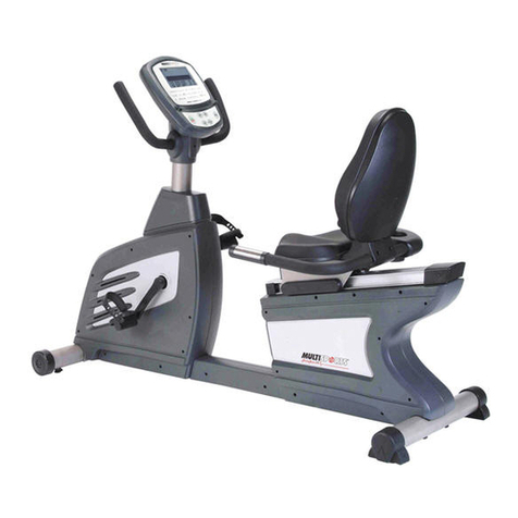
MultiSports Elliptix 880L User manual

1
Owner’s Manual

INDEX
IMPORTANT NOTICE…………………………………………
P. 1
ASSEMBLY TOOLS & HARDWARE MEASUREMENTS…
P. 2
ASSEMBLY INSTRUCTIONS…………………………………
P. 3-11
COMPUTER INSTRUCTIONS………………………………...
P. 12-13
PARTS LIST……………………………………………………..
P. 14-15
EXPLODED DRAWING………………………………………..
P. 16-17
The Specifications and descriptions in this manual were accurate at the time of
printing. Improvement is a constant goal at MultiSports; therefore we reserve the right
to make changes in specifications at any time without notice and without incurring
obligation.
The information in this manual is given in good faith. However any person who uses
this information in any way, does so entirely at his or her own risk. Neither
MultiSports, nor its representatives can accept responsibility for any damage or injury
incurred as a result of information presented here except under the terms of warranty
of MultiSports products.

1
Congratulations on your purchase of the new MultiSports equipment. Although we go to the great
lengths to ensure the quality of our products, occasionally errors or omissions occur. Should you find
a missing or defective part in this product, please contact us within thirty days for a replacement by
calling us at 713-460-8188, emailing us at mssales@swbell.net or visiting our web site at
www.multisportsfitness.com. *Please provide the equipment “item number” and “part number”
when requesting parts.
IMPORTANT SAFETY INFORMATION
WARNING:
Before starting any exercise program, it is recommended that you consult your physician, especially
for persons with pre-existing health problems. Before using the new equipment, please review this
manual to learn about the features, functions, and safety operations. Should you experience any
irregular physical conditions such as dizziness, severe muscle or joint pain, pain in your chest or
should any other symptoms appear: STOP EXERCISING and consult with your physician
immediately.
**MultiSports assumes no responsibility for personal injury or property damage sustained by or
through the use of this product.**
SAFETY TIPS AND PRECAUTIONS:
1. Read all instructions in this manual before using this equipment. It is the owner’s responsibility
to ensure that all users of this equipment are thoroughly informed of all warnings and
precautions. Use this equipment for its intended use as described in this manual.
2. Securely tighten all nuts and bolts and inspect and tighten all parts each time you use the
equipment. **Replace any worn parts immediately and if you find that any repairs are
needed, please keep the equipment out of use until repair.**
3. The safety level of the equipment can be maintained only if it is examined regularly for damage
and wear.
4. No more than one person should operate the equipment at one time.
5. To avoid any possibility of being struck by or caught between moving parts, by-standers should
not be within reach of the Elliptix Cross Trainer while it is in motion.
6. Keep your hands away from moving parts other than the designated handles.
7. Keep small children and pets away from the equipment at all times.
8. It is recommended that you do not initiate any type of exercising within 40 minutes after a meal.
9. Warm up before you start exercising to prevent injuries.
10. Appropriate clothing should be worn while exercising. Never wear loose clothing that could be
caught in moving parts. It is recommended that athletic support clothing be worn for both men
and women. Athletic shoes should always be worn while exercising. DO NOT USE with bare
feet, wearing sandals, or wearing only socks or stockings.
11. The user’s max weight to operate the equipment is 350 lbs.
12. The equipment should only be used on a level surface and is designed for indoor use only.
13. Never use the equipment around water or while you are wet. Using the unit around a pool, hot
tub or sauna will void the warranty and is potentially hazardous.

2
Assembly Tools & Hardware Measurements
M3/M4/M5/M6
Allen Wrenches
Screwdriver
Snap-Ring Socket
Assembly Tools
Wrench
NUT SIZE
M4
WASHER SIZE
mm
M6M5 M8
6010 20 30 5040 8070 90
Hardware Measurements
Bolt Length Inch
mm
10 14 16 25 29

3
Assembly Instructions
STEP 1
Fasten the Rear Stabilizer (LH) to the Main Frame (AH) using 2 Allen Bolts
(05A).
AH
05A
05A
LH
STEP 2
Slide the Handlebar Post (BH) into the Main Frame (AH). Please ensure the
Cable Wire (70A) does not get pinched and is pulled all the way through to the
front of the Handlebar Post (BH).
70A
BH
AH
LH
68A

4
As
STEP 3
Use your fingers to reach the hole on the bottom of the Handlebar Post (BH) and
pull out Cable Wire (70A) and Cable Wire (68A). Connect the two cables together
and push back into the hole. Then fasten the Main Frame (AH) and the Handlebar
Post (BH) using 6 Allen Bolts (06A) and 6 Spring Washers (08) with the Allen
Wrench provided.
BH AH
LH
70A
68A 06A
08
Assembly Instructions

5
Assembly Instructions
STEP 4
Attach the Front Stabilizer (MH) to the Handlebar Post (BH) using 2 Allen Bolts
(05A).
05A
BH
AH
MH
LH
NH

6
Assembly Instructions
STEP 5
Attach the Left Movable Handlebar Post (DH) to the Handlebar Post (BH). Then,
put one Snap Ring (04), one Washer (15), one Protecting Cover (14) ,one
Washer (15) and tighten using a Bolt (16A). Repeat connection on the right hand
side of the machine.
Remove the preassembled parts on the Disc (NH) and the Axle (C2) on the Movable
Handlebar Post (DH/CH) and set all of these removed parts aside, do not mix them up
(see diagram in STEP 8 for the parts needed to be removed and then reassembled
later in STEP 8). On the Disc Axle (NH) unscrew and remove one Allen Bolt (16A),
one Washer (15), one Protecting Cover (14), one Washer (15), one Snap-Ring (04),
one Washer (03), the Plastic Roller (P), one Wave Washer (86) and one Bushing (02).
Next on the Axle (C2) of the Movable Handlebar Post (DH/CH) unscrew and remove
one Snap-Ring (04). Repeat steps above on the other side of the Disc Axle (NH) and
the Axle (C2) on the Movable Handlebar (DH/CH).
04
14
15
16A
04
14 15 16A
DH
CH
NH
LH
AH
BH
C2
C2

7
Assembly Instructions
STEP 6
The Pedal Arms packed in the carton is as the picture below.
Firstly, you have to unloosen parts # 100, 101 and 102 on Right Pedal Arm.
Then, insert the Handlebar Post (D) to the Right Pedal Arm (IH) and bolt #100
through Handlebar Post (D) and tighten using #101 and #102. When inserting
bolt #100, please use a small tube as showed in “Drawing 1”to adjust the spacer
in the Handlebar Post (D) so that the bolt may go through Handlebar Post (D)
more easily. Following that, place the back half of the Right Pedal Arm (IH) onto
the top of Plastic Roller attached to the Steel Plate Axle. Repeat the process
above for the Left Pedal Arm (HH).
HH
IH
D
100
101
102
(Drawing 1)

8
STEP 7
Attach the left front side of the Connecting Tube (KH) to the Left Handlebar (DH).
Then slide the other end of the Connecting Tube (KH) onto the Disc Axle (NH).
Repeat connection on the right hand side of the machine.
CH
KH
DH
JH
LH
Assembly Instructions

9
STEP 8
The parts removed in STEP 5 will need to be reassembled on the Disc Axle (NH)
and the Axle (C2) of the Handlebar Post (DH). On the Axle (C2) of the Handlebar
post (DH) push on the Snap Ring (04) until it pops into its grove using the Socket
Tool provided (a rubber hammer may be needed to firmly place Snap Ring in
place. Please use rubber hammer GENTLY).
On the Disc Axle (NH) slide one Bushing (02), one Wave Washer (86), one Plastic
Roller (P) and one Washer (03) onto the Steel Disc Axle (N). Push on the Snap
Ring (04) until it pops into its grove using the Socket Tool provided (a rubber
hammer may be needed to firmly place Snap Ring. Please use rubber hammer
GENTLY). Then place one Washer (15), Protecting Cover (14) and another
Washer (15) on the Allen Bolt (16A) and attach to the Disc Axle (NH). Repeat
above on the other side.
15 13
15
16
14
15
13
14
16
15
13
04 03
16 14 04
15
86
03
02
P
03
86
14
15
04
16
P
02
Assembly Instructions

10
Assembly Instructions
STEP 9
Attach the Left Pedal Arm Holder Bracket (Q) to the Connecting Tube (KH) with 2
Allen Bolts (05). Repeat the process above on the Connecting Tube (JH).
Connect the Computer (67A) to the Cable Wires (68A & 69A) coming out of the
Handlebar Post (BH). Then fix the Computer (67A) to the Computer Support Plate
using 4 screws (63A).
63A
68A
69A
67A
05
Q
05
Q

11
77
60
F
71
61
60
61
62
62
67A
78
79
E
71
STEP 10
Fasten the upper Left Movable Handlebar (F) to the Lower Left Handlebar (DH) by
using 2 Carriage Bolts (60), Semicircle Washers (61) and Dome Nuts (62).
Repeat the process above on the Right Moveable Handlebar (E).
Attach the Water Bottle Holder (77) onto the Handlebar Post (BH) and fasten with 2
Screws (78).
Assembly Instructions

12
Computer Instructions
TO OPERATE
1. START PEDALING TO ACTIVATE COMPUTER.QUICK START:
A. Starting pedaling, press START once.
B. To reset values press START again, TIME, DISTANCE will count from zero.
C. Adjust work level by pressing UP and DOWN keys.
2. TO USE MANUAL OR MOUNTAIN PROGRAM:
A. Press STARTuntil you are in the RESET mode (▀AGE is flashing).
B. Press SELECT PROGRAM until the MANUAL or MOUNTAIN program is highlighted.
C. Press UP & DOWN keys to set your AGE then press ENTER.
D. Press UP & DOWN keys to set your WEIGHT then press ENTER.
E. Press UP & DOWN keys to set your PROGRAM LEVEL then press ENTER.
F. Press UP & DOWN keys to set the TIME then press START.
3. TO USE THE FAT BURN PROGRAM:
A. Press STARTuntil you are in the RESET mode (▀ AGE is flashing).
B. Press SELECT PROGRAM until the FAT BURN program is highlighted.
C. Press UP & DOWN keys to set your AGE then press ENTER.
D. Press UP & DOWN keys to set your WEIGHT then press ENTER.
E. Press UP & DOWN keys to set your PROGRAM LEVEL then press ENTER.
F. Press UP & DOWN keys to set the TIME then press START.

13
Computer Instructions
4. TO USE TARGET WATTS WHILE IN PROGRAM:
A. Press TARGET WATTS.
B. Press UP & DOWN keys to adjust level.
C. To cancel press TARGET WATTS again.
6. TO USE CONSTANT POWER WHIL IN PROGRAM:
A. Press CONSTANT POWER.
B. Press UP & DOWN keys to adjust level.
C. To cancel press CONSTANT POWER again.
7. TO USE THE FITNESS TEST PROGRAM:
A. Press START until you are in the RESET mode (▀AGE is flashing).
B. Press FITNESS TEST.
D. Press UP & DOWN keys to set your AGE then press ENTER.
E. Press UP & DOWN keys to set your WEIGHT then press START.
8. TO USE THE 60% HEART RATE PROGRAM:
A. Press START until you are in the RESET mode (▀AGE is flashing).
B. Press SELECT PROGRAM until the ●60% H.R. program is highlighted.
C. Press UP & DOWN keys to set your AGE then press ENTER.
D. Press UP & DOWN keys to set your WEIGHT then press ENTER.
E. Press UP & DOWN keys to set the TIME then press START.
8. TO USE THE 85% HEART RATE PROGRAM:
A. Press START until you are in the RESET mode (▀AGE is flashing).
B. Press SELECT PROGRAM until the ●85% H.R. program is highlighted.
C. Press UP & DOWN keys to set your AGE then press ENTER.
D. Press UP & DOWN keys to set your WEIGHT then press ENTER.
E. Press UP & DOWN keys to set the TIME then press START.
9. TO USE THE TARGET HEART RATE PROGRAM:
A. Press START until you are in the RESET mode (▀AGE is flashing).
B. Press SELECT PROGRAM until the ●TARGET H.R. program is highlighted.
C. Press UP & DOWN keys to set your AGE then press ENTER.
D. Press UP & DOWN keys to set your WEIGHT then press ENTER.
E. Press UP & DOWN keys to set the TIME then press START.
F. Press UP & DOWN keys to set your desired HEART RATE TARGET, then press ENTER.

14
ECT-880L PARTS LIST * Indicates pre-assembled parts
NO.
DESCRIPTION
Q'TY
NO.
DESCRIPTION
Q'TY
AH
Main Frame
1pc
06A
Allen Bolt M8x65L
6pcs
BH
Handlebar Post
1pc
*07
Screw M4x15L
12pcs
*CH
Right Handlebar
1pc
08
Spring Washer M8
14pcs
*DH
Left Handlebar
1pc
*09
Rivet Nut M8
8pcs
E
Right Movable Handlebar
1pc
*09A
Rivet Nut M8
4pcs
F
Left Movable Handlebar
1pc
*10
Spacer
2pcs
HH
Left Pedal Arm
1pc
*13
Snap-Ring 42
8pcs
IH
Right Pedal Arm
1pc
*13A
Snap-Ring 52
2pcs
JH
Right Connecting Tube
1pc
14
Φ54 Protecting Cover
4pcs
KH
Left connecting Tube
1pc
15
Washer φ16xφ7x1.5t
8pcs
LH
Rear Stabilizer
1pc
16A
Bolt M6x12L
4pcs
MH
Front Stabilizer
1pc
*17
Allen Bolt M8x50L
4pcs
*NH
Plastic Disc
2pcs
*18
Allen Bolt M8x25L
4pcs
P
Plastic Roller with Bearing #6004
4sets
*19
End Cap 30x60
4pcs
*Q
Pedal Arm Holder Bracket
2pcs
*20
Pedal (Right, Left)
1set
*R
Disc Axle
2pcs
*21A
Connecting Tube Cover (R)
2pcs
*S
Belt Wheel
2pcs
*22A
Connecting Tube Cover (L)
2pcs
*T
Rubber Stand
1pc
*23A
Right Housing
1pc
*U
Housing Holder
1pc
*24A
Left Housing
1pc
*V
Generator
1pc
*25
Rear Stabilizer End Cap
2pcs
*W
Belt Holder Plate
2pcs
*26
Front Stabilizer End Cap
2pcs
*X
Axle Holder
3pcs
*27
Screw M4x15L
4pcs
*XH
Idle Wheel Axle Holder
1pc
*28
Axle φ17
2pcs
*Y
Generator Spacer
1pc
*29
Bearing #30203
4pcs
*Z
IC
1pc
*30
Screw M4x10L
16pcs
*01
Bearing #6004C3
12pcs
*31
Nylon Nut M8
8pcs
*02
Bushing φ25.4xφ20x13t
4pcs
*32
Washer φ16x9x1.5t
4pcs
*03
Washer φ25.4x2t
6pcs
*33
Washer φ35x9x2t
4pcs
04
Snap-Ring 20
13pcs
*35
Hex Nut M25xP1.5x6t
4pcs
05
Bolt M8x15L
4pcs
*36A
Belt Axle
1pc

15
05A
Bolt M8x20L
4pcs
*36B
Belt Axle
1pc
ECT-880L PARTS LIST * Indicates pre-assembled parts
NO.
DESCRIPTION
Q'TY
NO.
DESCRIPTION
Q'TY
*37
Nut M14xP1.5x6t
2pcs
*74A
Hand-Pulse Foam Grip
2pcs
*38A
Disc Cover
2pcs
*75
Spacer φ20
2pcs
*44
Allen Bolt M6x10L
16pcs
*76
Rivet Nut M5
2pcs
*44A
Allen Bolt M6x15L
4pcs
*77
Water Bottle Holder
1pc
*45
Idle Wheel Axle Cover
2pcs
*78
Allen Bolt M5x20L
2pcs
*45A
Idle Fixed Holder
1pc
79
Water Bottle (Optional)
1pc
*46
Bearing #6204
3pcs
*80
Adjusting Bracket
2pcs
*47
Bushing φ52xφ47x2t
1pc
*81
Bracket for Chain Cover
1pc
*47A
Bushing φ31xφ25x13t
1pc
*82
Foam Roller φ11x3tx61L
2pcs
*50A
Idle Wheel Support Plate
1pc
*85A
Connecting Tube End Cap
2pcs
*50B
Idle Wheel Support Plate
1pc
*86
φ20 Wave Washer
6pcs
*51A
Support Plate
1pc
87
Hardware Kit & Tools
1set
*53A
Allen Bolt M8x12L
3pcs
Allen Wrench (M3, M4, M5, M6)
*53B
Hex Bolt M8x20L
4pcs
Wrench, Screwdriver, Snap-Ring Socket
*54
Belt Wheel Adjuster M8x90L
1pc
*88
Bearing #6205
2pcs
*54A
Belt Wheel Adjuster M8x60L
1pc
*89
Bearing #6205C3
2pcs
*56
Hex Nut M8
4pcs
*90
Allen Bolt M5x15L
3pcs
60
Carriage Bolt M8x45L
4pcs
*91
Cross Screw M5x10L
4pcs
61
Semicircle Washer M8
4pcs
*92
Cross Screw M5x15L
2pcs
62
Dome Nut M8
4pcs
*93
Cross Screw M5x20L
4pcs
63A
Bolt M5x15L
4pcs
*94
Hex Bolt M8x15L
8pcs
*64
Screw M4x15L
2pcs
*95
Screw 1/4”x3/4”L
1pc
*65A
1” End Cap
2pcs
*96
Spring Washer M5
7pcs
*66
Hand Pulse
2pcs
*97
Washer φ10xφ5x1t
6pcs
67A
Computer
1pcs
*98
Nylon Nut M5
6pcs
68A
Cable Wire
1pcs
*99A
Belt J10 35”L
1pc
69A
Hand-Pulse Wire
1set
*99B
Belt J6 48”L
1pc
*70A
Computer Cable
1pc
100
Axle φ20
2pcs
*71
φ31.8 End Cap
2pcs
101
Protecting Cover
4pcs

16
*73
Movable Handlebar Foam Grip
2pcs
102
Allen Bolt M6*15
4pcs
Exploded Drawing
71
LH
25
27
19
HH
31
32
33
20
17
18
82
Q
05
09
01
13
30
22A
21A
30
KH
AH
05A
05A
07
24A
F
73
60
16A 14
15 P
04
03 86
13
02
01
02
P
74A
67A
66
66
63A
69A
68A
64
75
86
04
75 86 04
27
27 26
26
09
05A
05A
06A
08
70A
01
04
14
15
16A
01
61 62
04
38A
NH
30
37 R
T
95
98
97
91
44
44
09
09A
U
Z
92
44A
97
98
44
44
44A
97
98
85A
79
65A
78
76
77
BH
MH
DH
30
44
56
28
29
80
81
100
101
102
29
10
101
102
01
01
18

17
Exploded Drawing
71
25
27
19
18 17
32
31
33
IH
20
73
E
04
P16A
15
14
03
13
02
01
86
02
P
08
53B
56
08
60
01
0104
14 15 16A
61
62
04
13
01
30
30
07
NH
30
38A 37
23A
R
35
13A
88
X
W
S
94
44
45
46
50B
XH
89
35
47A
54A 44
36A
44 54
90
96
45A
50A
47
46
04
V
53A
93
Y
96
35
88
X
94
SX
36B
W
89
13A
35
85A
CH
22A
21A
JH
Q
09
82
05
51A
99A
99B
30
56
01
01 103
28
29
80
100
101
102
29
101
102

18
4660 Pine Timbers, Suite 138, Tx77041
Phone: 713-460-8188 Fax:713-460-8180
Web-site:www.multisportsfitness.com E-mail:mssales@swbell.net
l
Table of contents
Other MultiSports Fitness Equipment manuals
Popular Fitness Equipment manuals by other brands

Christopeit Sport
Christopeit Sport Basic Concept Assembly and exercise instructions

Bodyworx
Bodyworx EFX580 manual

Precor
Precor Resolute RSL 619 Getting started guide

HOMCOM
HOMCOM A91-065 Assembly instruction

Energetics
Energetics ET 12.0 ERGOMETER instructions

Stamina
Stamina InMotion 55-1618B owner's manual