Hand Extruder MEK-40,65 / MAK-40,65
Page 4/20 Issue 08.2008/Rev. 01 MUNSCH Kunststoff-Schweißtechnik GmbH
1 General
These operating instructions must always
be available at the place of use of the hand ex-
truder.
The objective of these operating instructions is to
support operators in familiarizing themselves with the
hand extruder and in using its functions for the in-
tended service.
These operating instructions provide important in-
formation for the safe, workmanlike and economical
operation of the hand extruder. Their observance
helps avoid danger, minimize repair costs and down-
times, enhance reliability, and extend the service life
of the hand extruder.
These operating instructions must be observed by all
persons working with/on the hand extruder. Such
work includes, for instance:
•operation,
•maintenance, inspection and repair
•transport.
The hand extruder may only be mounted, operated
and maintained by trained personnel.
In addition to the operating instructions and the
national and local accident prevention regulations
applicable at the place of use, the acknowledged
technical rules for safe and proper working practices
must be observed.
These operating instructions provide basic informa-
tion to be observed for operation and maintenance.
For this reason, it is imperative that they be read by
the specialist personnel/Operator prior to placing the
hand extruder in service and that they always be
available at the place of use.
Apart from the general safety instructions under sec-
tion “Safety“, also the special safety instructions
given under the respective sub-sections must be
adhered to.
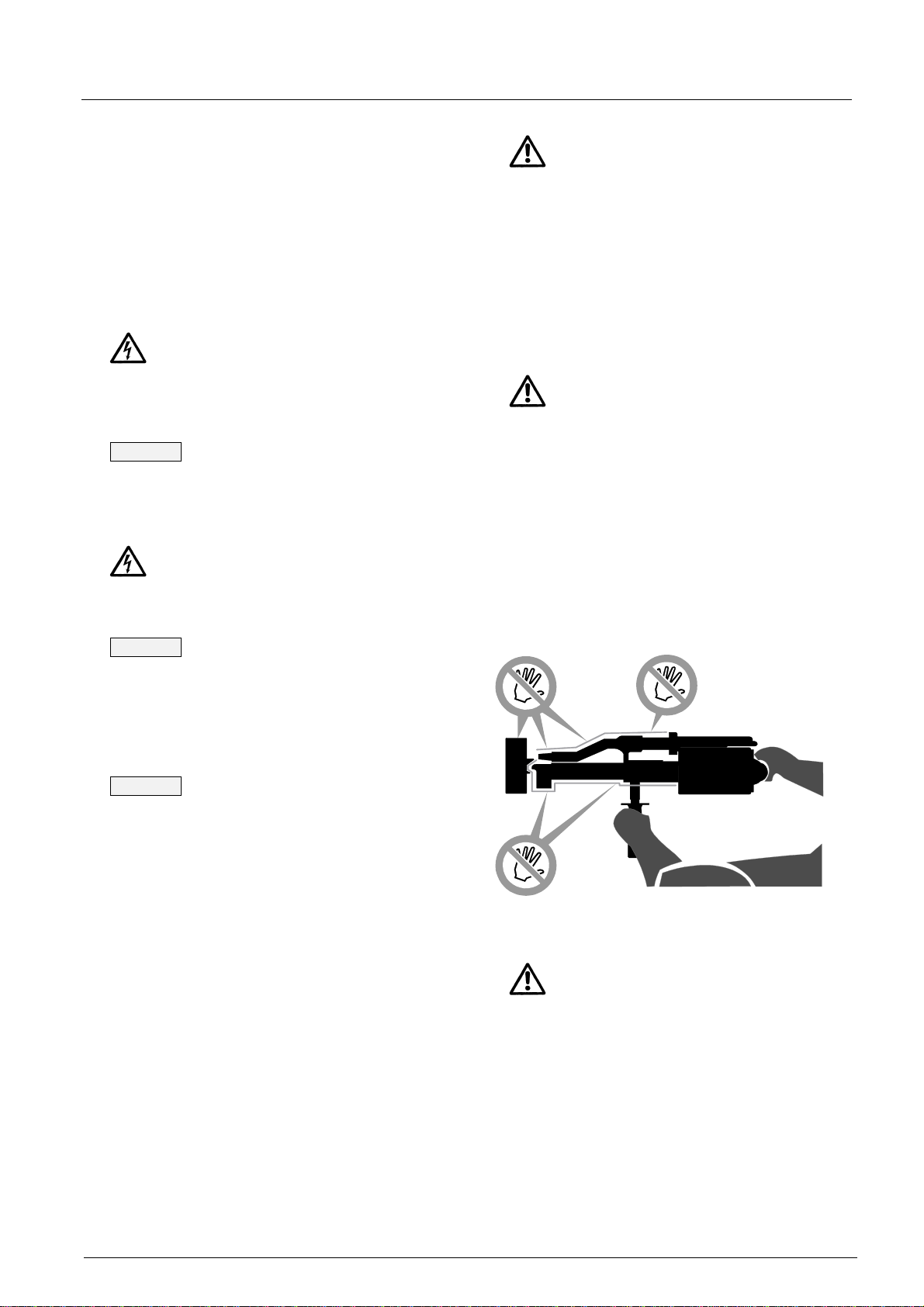
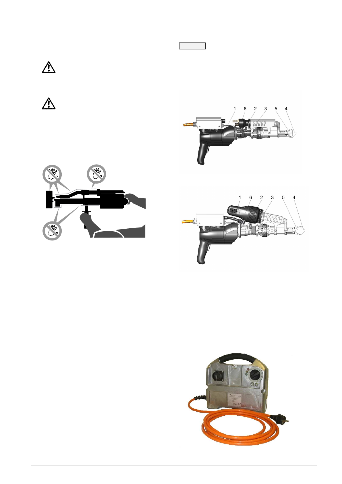
Non-observance of the safety instructions
may cause hazards to persons and the environment
or damage to the hand extruder.
Moreover, failure to observe the safety instructions
may lead to the forfeiture of any damages.
Non-observance of the safety instructions may in
particular involve the following risks:
•failure of important hand extruder functions,
•hazards to persons due to electrical and me-
chanical impacts including risk of burns,
•hazards to the environment due to vapour-phase
hazardous substances,
•risk of fire.
2 Safety
These operating instructions provide basic informa-
tion to be observed for operation and maintenance.
For this reason, it is imperative that they be read by
the specialist personnel/Operator prior to placing the
hand extruder in service and that they always be
available at the place of use.
Safe operation of the hand extruder presupposes
that the instructions under section 1 – General – of
these operating instructions are complied with. In no
case must the limit values indicated be violated.
Intact and unaltered hand extruders conform to the
applicable codes and standards and meet all regula-
tory limit values regarding EMC (electromagnetic
discharges and interference immunity). For the coun-
try-specific limit values to be observed, the Operator
should consult the local electric utility. Nevertheless,
the hand extruders emit electromagnetic fields within
the acceptable limits. Electromagnetic fields may
interfere with the operation of vital electronic devices
(e.g. cardiac pacemakers). Persons wearing a car-
diac pacemaker should therefore consult their physi-
cian before using the machine.
In addition to the operating instructions and the
national and local accident prevention regulations
applicable at the place of use, the acknowledged
technical rules for safe and proper working practices
must be observed.
Apart from the general safety instructions under sec-
tion “Safety“, also the special safety instructions
given under the respective sub-sections must be
adhered to.
Any working practices posing a safety risk are pro-
hibited.