Murata Cat-M1/NB-IoT User manual

Copyright © Murata Manufacturing Co., Ltd. All rights reserved. 2020
Murata LTE-M EVK User Guide, 5/4/2020 Page 1of 44 www.murata.com
Revision History
Revision
Date
Change Description
1.0
01/31/2020
Initial version for new Type1SC/Type1WG EVB with printed antenna
1.1
02/26/2020
Minor updates including email contact
1.2
4/7/2020
Fixed ToC error
Type1SC/Type1WG
Type1SC-DM
EVK User Guide
LTE CAT-M1 /
NB-IoT EVK

Copyright © Murata Manufacturing Co., Ltd. All rights reserved. 2020
Murata LTE-M EVK User Guide, 5/4/2020 Page 2of 44 www.murata.com
Table of Contents
REVISION HISTORY.............................................................................................................................................................. 1
TABLE OF CONTENTS ......................................................................................................................................................... 2
1INTRODUCTION............................................................................................................................................................5
1.1 Scope......................................................................................................................................................................... 5
1.2 Audience ....................................................................................................................................................................6
1.3Contact Info and Support...........................................................................................................................................6
1.4 Text Conventions .......................................................................................................................................................6
1.5 Kit Contents................................................................................................................................................................6
2DESCRIPTION...............................................................................................................................................................7
3POWER SUPPLY........................................................................................................................................................... 9
3.1 USB power supply......................................................................................................................................................9
3.2 External 5V supply ...................................................................................................................................................10
4SERIAL INTERFACES ................................................................................................................................................10
5INDICATION AND SERVICES ....................................................................................................................................11
5.1 Optical Indicators .....................................................................................................................................................11
5.1.1 LED1: PMU_EXT_ALARM status ...................................................................................................................11
5.1.2 LED2: PWM3 status........................................................................................................................................11
5.1.3 LED3: SMA / ANT select status ......................................................................................................................11
5.2 Services....................................................................................................................................................................11
5.2.1 Reset operation...............................................................................................................................................12
5.2.2 Recovery operation .........................................................................................................................................12
5.2.3 Wakeup operation ...........................................................................................................................................12
5.2.4 Reserved operation.........................................................................................................................................12
6MODULE IO INTERFACE............................................................................................................................................ 12
6.1 Arduino interface......................................................................................................................................................12
6.2 Expansion headers ..................................................................................................................................................13
7STARTUP PROCEDURE............................................................................................................................................. 15
7.1 Install PuTTY............................................................................................................................................................15
7.2 Connection to PC.....................................................................................................................................................15
7.3 AT/PPP port .............................................................................................................................................................16
7.3.1 AT commands .................................................................................................................................................17
7.3.2 From AT Channel to PPP Channel .................................................................................................................17
7.4 CLI port.....................................................................................................................................................................17
7.4.1 CLI commands ................................................................................................................................................18
7.4.2 Sending AT commands from CLI channel ......................................................................................................19
7.4.3 From CLI Channel to AT Channel...................................................................................................................19
8PPP LTE CONNECTION –WINDOWS.......................................................................................................................19
8.1 Creating a modem....................................................................................................................................................20
8.2 Creating PPP connection entry................................................................................................................................23
8.3 Establishing the LTE connection..............................................................................................................................27
8.4 Making the PPP connection.....................................................................................................................................28
9CURRENT MEASUREMENT.......................................................................................................................................32
10 FIRMWARE UPGRADE...............................................................................................................................................33
11 EVK SCHEMATICS .....................................................................................................................................................34

Copyright © Murata Manufacturing Co., Ltd. All rights reserved. 2018
Type 1SC EVK User Guide, v1.3, 5/4/2020 Page 3of 44 www.murata.com
12 SAFETY RECOMMENDATIONS.................................................................................................................................43
12.1 Disposal of this product in the European Union.......................................................................................................43
12.2 Disposal of this product in other countries outside the European Union.................................................................43
13 ACRONYMS.................................................................................................................................................................44

Copyright © Murata Manufacturing Co., Ltd. All rights reserved. 2018
Type 1SC EVK User Guide, v1.3, 5/4/2020 Page 4of 44 www.murata.com
LIST OF FIGURES
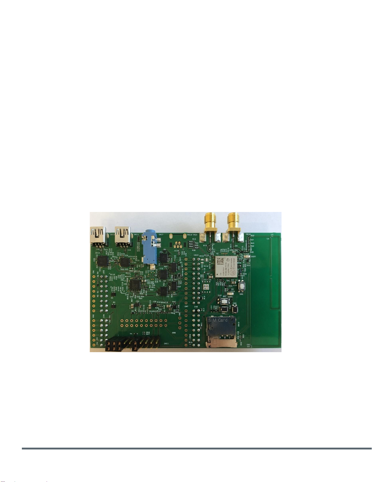
Figure 1 Evaluation Board with Type1SC (top) and Type1WG (bottom)................................................................................5
Figure 2 Murata LTE module development kit contents .........................................................................................................6
Figure 3 Murata LTE module evaluation board (top view)......................................................................................................7
Figure 4 Murata LTE module evaluation board (bottom view)................................................................................................8
Figure 5 Power supply block diagram.....................................................................................................................................9
Figure 6 USB connectors location...........................................................................................................................................9
Figure 7 Ext_Vin pin location on bottom side of EVB ...........................................................................................................10
Figure 8 Exported UART interfaces......................................................................................................................................10
Figure 9 LED locations on EVB.............................................................................................................................................11
Figure 10 Button locations on EVB.......................................................................................................................................11
Figure 11 EVK setup.............................................................................................................................................................15
Figure 12 COM ports assignment shown in Device Manger ................................................................................................16
Figure 13 PuTTY configuration for AT port...........................................................................................................................16
Figure 14 PuTTY configuration for CLI port..........................................................................................................................18
Figure 15 Prompt for CLI Port...............................................................................................................................................18
Figure 16 CLI Commands.....................................................................................................................................................19
Figure 17 Modems Tab.........................................................................................................................................................20
Figure 18 ‘Add New Hardware Wizard’ .................................................................................................................................20
Figure 19 Next Screen ..........................................................................................................................................................21
Figure 20 Modem Selection ..................................................................................................................................................21
Figure 21 Click Selected Ports..............................................................................................................................................22
Figure 22 Modems Installed..................................................................................................................................................22
Figure 23 Set the Baud Rate.................................................................................................................................................23
Figure 24 Accessing dial-up connection ...............................................................................................................................24
Figure 25 Creating Dial-up Connection.................................................................................................................................24
Figure 26 Connection is Ready.............................................................................................................................................25
Figure 27 Set Connection Anyway........................................................................................................................................25
Figure 28 Access for Change Adapter Settings....................................................................................................................26
Figure 29 Change Adapter Settings......................................................................................................................................26
Figure 30 PPP Properties .....................................................................................................................................................27
Figure 31 CLI Console..........................................................................................................................................................28
Figure 32Enabling hardware control.....................................................................................................................................28
Figure 33 PPP Connection –Network Connections Panel...................................................................................................29
Figure 34 Windows 10 Pop-Up Screen.................................................................................................................................29
Figure 35: Click “PPP”...........................................................................................................................................................30
Figure 36 Connect “PPP” ......................................................................................................................................................30
Figure 37 Options..................................................................................................................................................................31
Figure 38 PPP Connection....................................................................................................................................................31
Figure 39 PPP Connection....................................................................................................................................................32
Figure 40 Power supply setup with Keysight power module ................................................................................................33
Figure 41 Image Burn Tool configuration..............................................................................................................................34
LIST OF TABLES
Table 1 Default CN11 connections .........................................................................................................................................8
Table 2 EVB dimensions.........................................................................................................................................................9
Table 3 Arduino shield headers: CN3 (power) + CN4 (analog) ............................................................................................13
Table 4 Arduino shield headers: CN10 (D8-D15) + CN9 (D0-D7)........................................................................................13
Table 5 Expansion headers pinout: CN3 + CN4...................................................................................................................14
Table 6 Expansion headers pinout: CN10 + CN9.................................................................................................................14

Copyright © Murata Manufacturing Co., Ltd. All rights reserved. 2018
Type 1SC EVK User Guide, v1.3, 5/4/2020 Page 5of 44 www.murata.com
1 INTRODUCTION
1.1 Scope
This document provides the general operation instructions for the Murata Cat-M1/NB-IoT Evaluation
Kit (EVK) based on the evaluation board with printed antenna and headers CN3, 4, 9, 10, 11
installed, as shown below. Please ensure that the board is the correct version prior to using this
document. In the ensuing discussion, Murata LTE module refers to the module mounted on the
evaluation board, so it could be either Type1SC or Type1WG.
Figure 1 Evaluation Board with Type1SC (top) and Type1WG (bottom)
CN11
CN3
CN4
CN10
CN9
Type1SC
Type1WG

Copyright © Murata Manufacturing Co., Ltd. All rights reserved. 2018
Type 1SC EVK User Guide, v1.3, 5/4/2020 Page 6of 44 www.murata.com
1.2 Audience
This document is intended for software/firmware, hardware and systems engineers to evaluate and
develop applications with Murata’s Type1SC and Type1WG LTE Cat M1/NB-IoT modules.
1.3 Contact Info and Support
For general contact, technical support services, technical questions and report documentation errors
1.4 Text Conventions
Danger –This information MUST be followed or catastrophic equipment failure or bodily
injury may occur.
Caution/Warning
Alerts the user to important points about using the EVK; if these points are not followed,
the EVK and end user equipment may fail or malfunction.
Tip/Information –Provides advice and suggestions that may be useful when using the
EVK.
1.5 Kit Contents
The Murata LTE module EVK package contains the following items:
•1 Type1SC (or Tye1WG) Evaluation Board (EVB)
•2 mini-USB cables
Figure 2 Murata LTE module development kit contents

Copyright © Murata Manufacturing Co., Ltd. All rights reserved. 2018
Type 1SC EVK User Guide, v1.3, 5/4/2020 Page 7of 44 www.murata.com
2 DESCRIPTION
The EVK is an evaluation and application development kit for the Murata Type1SC and Type1WG
LTE modules. It includes an Evaluation Board (EVB) with an Arduino shield interface which allows
the EVB to be used across various Arduino based MCU development platforms such as the STM32
Nucleo-64 boards.
Some major components of the EVB are listed and shown below.
•Type1SC (or Type1WG) module
•2 mini-USB ports
•LTE/GNSS antenna
•1 micro SIM slot
•3 LEDs
•4 buttons
•SMA connector for RF testing
•Pads for accessing Murata LTE module IO pins
oArduino headers supporting 3.3V/5V IOs for UART modem control interface
oExpansion headers for access to the module pins
oJumpers CN11 to facilitate current measurements
Figure 3 Murata LTE module evaluation board (top view)
Murata LTE module
SMA
CN11
uSIM
socket
Antenna
USB/UARTs

Copyright © Murata Manufacturing Co., Ltd. All rights reserved. 2018
Type 1SC EVK User Guide, v1.3, 5/4/2020 Page 8of 44 www.murata.com
Figure 4 Murata LTE module evaluation board (bottom view)
The default CN11 jumper settings are shown below:
Jumper connection
Description
Top
Bottom
20
1
Connect LDO_EN to 4V3_SUPP
19
2
Connect VBAT_FEM to VBAT_FEM_LDO
18
3
Connect VBAT to Vsys
15
6
Connect ANT_SEL to GND –select SMA path
Table 1 Default CN11 connections
The nominal EVB physical dimensions are as shown below.
VBAT_FEM
Arduino Header
Expansion Header
CN11 pin 1
CN3
CN4
CN10
CN9
LDO_EN
VBAT
ANT_SEL

Copyright © Murata Manufacturing Co., Ltd. All rights reserved. 2018
Type 1SC EVK User Guide, v1.3, 5/4/2020 Page 9of 44 www.murata.com
Dimension
Value
(mm)
Description
Height
19
EVB height including Arduino connector
Length
100
EVB length
Width
70
EVB width
Table 2 EVB dimensions
3 POWER SUPPLY
The EVB power can be provided by USB hosts or an external 5V supply which is then converted by
LDOs to create the 3.3V and 1.8V needed for the onboard circuits. There is no switch needed for
selecting a particular supply. Instead, diodes are installed to provide reverse current protection for
each individual supply. Jumpers CN11 may be used to measure the current consumption of the
module as described in Section 9. A block diagram of the power supply connections is shown below.
Figure 5 Power supply block diagram
3.1 USB power supply
In the default configuration, the EVB is connected to a PC through at least one of the two mini-USB
ports CN13 and CN14. These connections provide the USB-UART serial interfaces and serve as the
power sources for the EVB. The mini-USB connector locations are as shown below in Figure 6.
Figure 6 USB connectors location

Copyright © Murata Manufacturing Co., Ltd. All rights reserved. 2018
Type 1SC EVK User Guide, v1.3, 5/4/2020 Page 10 of 44 www.murata.com
3.2 External 5V supply
The EVB can also be powered by applying 5V to the Ext_Vin pin of the Arduino interface. This is pin
8 on the CN3 header which is located on the bottom side of the EVB as shown in Figure 7.
Figure 7 Ext_Vin pin location on bottom side of EVB
4 SERIAL INTERFACES
The EVB exports 3 module UART ports through either the USB-UART mini-USB connectors or the
Arduino header. A block diagram for this is shown in Figure 8.
Figure 8 Exported UART interfaces
In the default configuration, USB ports CN13 (UART A & C) and CN14 (UART B) are connected to a
PC for application testing and development; the Arduino interface is not used.
The host control for the modem is accomplished through the UART B (CN14) interface. There are
two possible options:
•Use a PC application (e.g., PuTTY): connect a mini-USB cable to CN14 and disconnect the
Arduino interface. See Section 0 for more instructions.
•Use the Arduino interface (e.g., Nucleo 64 board): connect MCU to the Arduino interface and
disconnect the mini-USB cable from CN14. See Section 6.1 for the detailed Arduino interface
pin assignments.
UART A & C (CN13) are used for CLI and debugging. See Sections 7.4 for more details.
Ext_Vin
3V3_IO

Copyright © Murata Manufacturing Co., Ltd. All rights reserved. 2018
Type 1SC EVK User Guide, v1.3, 5/4/2020 Page 11 of 44 www.murata.com
5 INDICATION AND SERVICES
5.1 Optical Indicators
The EVB has 3 LEDs which serve as status indicators. Their locations on the EVB are shown below.
Figure 9 LED locations on EVB
5.1.1 LED1: PMU_EXT_ALARM status
LED1 shows the power save mode status of the module. It is on whenever the module is not in one
of the low power sleep states.
5.1.2 LED2: PWM3 status
LED2 is the status of the PWM3 pin.
5.1.3 LED3: SMA / ANT select status
LED3 indicates the antenna selection status: ON if the SMA connector is connected to the LTE RF
path; OFF if the RF is routed to the onboard antenna. By default, the SMA connector is selected.
5.2 Services
The EVB has four push buttons which can be used to reset the module or place it in recovery mode.
Figure 10 Button locations on EVB
LED3
LED2
LED1
SW2
SW3
SW1
SW4

Copyright © Murata Manufacturing Co., Ltd. All rights reserved. 2018
Type 1SC EVK User Guide, v1.3, 5/4/2020 Page 12 of 44 www.murata.com
5.2.1 Reset operation
The module can be reset by pressing buttons SW1.
5.2.2 Recovery operation
The module can be placed in recovery mode by the following sequence:
1. Press and hold SW4
2. Press and release SW1
3. Release SW4
5.2.3 Wakeup operation
While the module is in sleep mode, press and hold SW2 to wake it up.
Pressing SW2 is only necessary if a PC terminal is not connected to the Murata module
through the USB via CN14. Otherwise, the CTS signal from that USB-UART connection will
keep the module awake.
5.2.4 Reserved operation
The function of SW3 is currently reserved.
6 MODULE IO INTERFACE
The EVB exports the Arduino and expansion headers for access to the module IOs.
6.1 Arduino interface
The module exports the modem UART control interface to the Arduino headers. The external MCU
signals are level-shifted to the 1.8V levels required by the module. To use the Arduino interface,
disconnect the cable from mini-USB port CN14 and establish the following connections to the Arduino
headers:
•MCU reference voltage to IOREF
•5V supply to VIN
•MCU GND to EVB GND
•MCU UART to corresponding modem UART pins
The pin assignments for the Arduino interface are shown below.
•I/Os levels are defined by IOREF to be either 1.8V/3V/5V
•Signal with (DNS) is not connected by default, but can be connected with a 0Ωresister
•Signal with (0Ω) is connected by default, but can be disconnected by removing the 0Ωresister
Signal
Pin#
EVB
Direction
Description
1
IOREF
2
IO_REF
I
MCU IO voltage reference
3
RESET_IO (0Ω)
Signal to reset modem if pins 5 and 16 of
CN11 are connected.
4
5
GND
6
GND
--
Ground
GND
7
GND
--
Ground

Copyright © Murata Manufacturing Co., Ltd. All rights reserved. 2018
Type 1SC EVK User Guide, v1.3, 5/4/2020 Page 13 of 44 www.murata.com
VIN
8
Ext_Vin
I
5V input for EVB. See more details in
Section 3.2.
A0
1
UART0_RTS_IO (0Ω)
O
Level shifted UART0_RTS
A1
2
UART0_CTS_IO (0Ω)
I
Level shifted UART0_CTS
A2
3
A3
4
A4
5
RESET_IO (DNS)
I
Optional signal to reset modem
A5
6
LDO_EN (DNS)
I
Optional signal to enable VBAT and
VBAT_FEM LDOs
Table 3 Arduino shield headers: CN3 (power) + CN4 (analog)
Signal
Pin#
EVB
Direction
Description
D15
10
D14
9
AREF
8
GND
7
GND
--
Ground
D13
6
D12
5
D11
4
D10
3
D9
2
PWM0_RST_IND_IO(DNS)
O
Optional level shifted signal
D8
1
D7
8
SC_SWP_IO (DNS)
O
Optional level shifted signal
D6
7
D5
6
D4
5
PMU_WAKEUP_IO (DNS)
I
Optional level shifted signal
D3
4
D2
3
D1
2
UART0_RX_IO (0Ω)
I
Level shifted UART0_RX
D0
1
UART0_TX_IO (0Ω)
O
Level shifted UART0_TX
Table 4 Arduino shield headers: CN10 (D8-D15) + CN9 (D0-D7)
6.2 Expansion headers
The EVB provides a set of expansion headers to access the module IO pins. The assignments for
these headers are shown below.
•Signal with (DNS) is not connected by default, but can be connected with a 0Ωresister
•Signal with (0Ω) is connected by default, but can be disconnected by removing the 0Ωresister
Signal
Pin#
EVB
Level
Direction
Description
XP1
16
XP2
15
IO_REF
IOREF
I
MCU IO voltage reference
XP3
14
XP4
13

Copyright © Murata Manufacturing Co., Ltd. All rights reserved. 2018
Type 1SC EVK User Guide, v1.3, 5/4/2020 Page 14 of 44 www.murata.com
XP5
12
4V3_SUPP
4.3V
O
5V output from USB ports after diode
drop
XP6
11
XP7
10
XP8
9
XA0
12
UART0_RTS_IO
IOREF
I/O
Level shifted UART0_RTS
XA1
11
UART0_CTS_IO
IOREF
I/O
Level shifted UART0_CTS
XA2
10
XA3
9
XA4
8
XA5
7
Table 5 Expansion headers pinout: CN3 + CN4
Signal
Pin#
EVB
Level
Direction
Description
XD15
11
XD14
12
XDA
13
VDDIO
1.8V
O
1.8V reference from modem
XDG
14
XD13
15
XD12
16
XD11
17
XD10
18
XD9
19
PWM0_RST_IND_IO
IOREF
O
Optional level shifted signal
XD8
20
PWU_EXT_ALARM_IO
IOREF
O
Level shifted signal indicating
Device Status
XD7
9
SC_SWP_IO
IOREF
O
Optional level shifted signal
XD6
10
XD5
11
XD4
12
PMU_WAKEUP_IO
IOREF
I
Optional level shifted signal to
wakeup module
XD3
13
XD2
14
PMU_POWER_BUTTON_IO
IOREF
I
Level shifted Modem power
button
XD1
15
XD0
16
Table 6 Expansion headers pinout: CN10 + CN9

Copyright © Murata Manufacturing Co., Ltd. All rights reserved. 2018
Type 1SC EVK User Guide, v1.3, 5/4/2020 Page 15 of 44 www.murata.com
7 STARTUP PROCEDURE
Unpack the EVK package and use the following steps to setup the reference PC environment and
configure the EVK. The ensuing discussions are based on a PC running Windows 10 Pro.
Do not connect to the Arduino interface.
7.1 Install PuTTY
Download and install PuTTY for Windows from https://www.putty.org. This is the recommended
serial port console for PC serial communication with the module.
7.2 Connection to PC
Connect two USB cables from a PC to the two mini-USB ports labeled CN13 and CN14. The driver
should be automatically installed for the two UART ports (A & C) associated with CN13.
Figure 11 EVK setup
The driver for UART B associated with CN14 needs to be installed manually.
•Open the following web page: https://www.silabs.com/products/development-
tools/software/usb-to-uart-bridge-vcp-drivers.
•Download the latest version of universal driver for Windows 10.
•Unzip the downloaded zip file, and run CP210xVCPInstaller_x64.exe to install the driver.
After the above steps, there should be three COM ports shown in Device Manager -- one for Debug
(e.g. COM8, 921600 baud), one for CLI (e.g. COM9, 115200 baud), and one for AT (COM13, 115200
baud). See below an example screenshot of the Device Manager.

Copyright © Murata Manufacturing Co., Ltd. All rights reserved. 2018
Type 1SC EVK User Guide, v1.3, 5/4/2020 Page 16 of 44 www.murata.com
Figure 12 COM ports assignment shown in Device Manger
7.3 AT/PPP port
By default, UART B is the dedicated AT/PPP port. Start a PuTTY session and connect to the AT port.
The baud and flow control of PuTTY session, respectively, need to be set to 115200 8N1 and
“None”.
If the driver is installed properly but there is no response from the module, use the CLI port to ensure
that the modem is not in the u-boot mode (See Section 7.4 for details).
Figure 13 PuTTY configuration for AT port

Copyright © Murata Manufacturing Co., Ltd. All rights reserved. 2018
Type 1SC EVK User Guide, v1.3, 5/4/2020 Page 17 of 44 www.murata.com
7.3.1 AT commands
The module supports a subset of standard 3GPP AT commands and a set of proprietary commands.
•Standard AT commands start with “AT+”,
•Proprietary AT commands start with “AT%”.
All commands are case insensitive.
Here is a list of some useful AT commands.
-at%ver to list versions
-at+cgmi to read name of manufacturer
-at+cgmm to read model number
-at+cgsn to read IMEI number
-at+cgmr to read software version
-at%ccid to check SIM card status
7.3.2 From AT Channel to PPP Channel
The user can switch between an AT channel to a PPP channel as follows. See Section 8 for the
details to create the PPP interface with a PC.
1. Connect a mini-USB cable to the CN14 (UART B) port.
2. Open a terminal shell to the AT channel COM port (the default functionality of UART B is AT
channel).
3. In order to switch to the PPP channel functionality, the user needs to run the ‘ATD*99’ AT
command.
4. After step #3, the AT channel will switch to a PPP channel, on which the user can establish a
PPP connection.
5. In order to switch back to AT channel functionality, the user needs to follow the steps below (in
the PPP terminal):
a. Enter the ‘+++’ command without pressing the ‘Enter’ key.
b. Wait for one second (at least).
c. Press the ‘Enter’ key.
6. After step #5, the terminal will suspend the PPP and switch back to an AT channel terminal.
7. Now the port accepts regular AT commands; ATO and AT%H0, respectively, can be used to
resume and terminate the PPP session.
7.4 CLI port
The CLI port is intended for testing purposes and allows the user to enter commands to interact with
the module.
Open PuTTY to the CLI port. The following screenshot shows how to save the configuration as
“COM9” for later use.

Copyright © Murata Manufacturing Co., Ltd. All rights reserved. 2018
Type 1SC EVK User Guide, v1.3, 5/4/2020 Page 18 of 44 www.murata.com
Figure 14 PuTTY configuration for CLI port
After connecting to the CLI port, check the prompt. If the prompt is “#”, that means the
firmware is in u-boot mode. Enter “boot” command to boot it up; after boot up, the prompt
should change to “>”. This is illustrated below.
Figure 15 Prompt for CLI Port
7.4.1 CLI commands
All supported CLI commands can be seen with the “help” command. The “help” command lists
categories of CLI commands. Use “help <category>” to see commands under a particular category.

Copyright © Murata Manufacturing Co., Ltd. All rights reserved. 2018
Type 1SC EVK User Guide, v1.3, 5/4/2020 Page 19 of 44 www.murata.com
Figure 16 CLI Commands
Here is a list of example CLI commands.
-ver to show the current version of the firmware installed
-ifconfig to show the interfaces
-ping 127.0.0.1 to ping an IP address
7.4.2 Sending AT commands from CLI channel
The CLI channel supports sending AT commands to the modem, as follows:
at <AT command>
For example:
-at at+cfun?
-at at%ccid
7.4.3 From CLI Channel to AT Channel
The user can switch a CLI channel to an AT channel as follows:
1. Connect a UART serial cable to the device’s CN13 (UART A & C) mini-USB connector.
2. Open a terminal shell to the CLI COM port (the default functionality of UART A is CLI).
3. To switch to the AT channel functionality, run the ‘serialSwitch’ CLI command.
4. After step #3, the terminal will switch to an AT channel terminal and the user can run normal
AT commands in it –there is no need for the extra “AT” as in the case with the CLI port.
5. To switch back to CLI functionality, run the ‘at%cli’ AT command.
6. After step #5, the terminal will switch back to a CLI terminal.
8 PPP LTE Connection – Windows
Connect both CLI and AT port from the EVB to PC. Use PuTTY to connect to CLI port to make sure
the modem is in application mode (“>” prompt is shown).

Copyright © Murata Manufacturing Co., Ltd. All rights reserved. 2018
Type 1SC EVK User Guide, v1.3, 5/4/2020 Page 20 of 44 www.murata.com
A valid SIM card inserted into the SIM slot is needed for LTE connection
Use the following steps to make the PPP connection for Windows to connect to the internet.
8.1 Creating a modem
1. Go to ‘Control Panel’ and select ‘Phone and Modem,’ select the ‘Modems’ tab, then click ‘Add.”
Figure 17 Modems Tab
The “Add Hardware Wizard” displays.
Figure 18 ‘Add New Hardware Wizard’
2. Click ‘Next’ to go to the next screen.
Table of contents
Other Murata Motherboard manuals

Murata
Murata PSemi PE43650 User manual

Murata
Murata MEMS User manual

Murata
Murata Ps DMS-EB User manual

Murata
Murata N1-2657 User manual

Murata
Murata 1LD User manual

Murata
Murata PKGX-16-4021 User manual

Murata
Murata 2AB User manual

Murata
Murata MEX-1031 User manual

Murata
Murata SprIoT 6UL User manual

Murata
Murata Type2EG BLE User manual